3.2 Swimming Pool Heat Pumps Location
The unit will perform well in any outdoor location provided that the follow-
ing three factors are presented:
1Fresh Air - 2Electricity - 3Pool lter piping
The unit may be installed virtually anywhere outdoors. For indoor pools
please consult the
supplier. Unlike a gas heater, it has no draft or pilot light problem in a windy
area.
DO NOT place the unit in an enclosed area with a limited air volume, where
the units discharge air will be re-circulated.
DO NOT place the unit to shrubs which can block air inlet. These locations
deny the unit of a continuous source of fresh air which reduces it eciency
and may prevent adequate heat delivery.
3.3 How Close To Your Pool?
Normally, the pool heat pump is installed within 7.5 metres of the pool. The
longer the distance from the pool, the greater the heat loss from the piping.
For the most part ,the piping is buried. Therefore, the heat loss is minimal for
runs of up to15 meters(15 meters to and from the pump = 30 meters total),
unless the ground is wet or the water table is high. A very rough estimate of
heat loss per 30 meters is 0.6 kW-hour,(2000BTU) for every 5°C dierence
in temperature between the pool water and the ground surrounding the pipe,
which translates to about 3% to 5% increase in run time.
3.INSTALLATION AND CONNECTION
10
2.SPECIFICATION
6
3.1 Installation illustration
Installation items:
The factory only provides the main unit and the water unit; the other items in the illustration
are necessary spare parts for the water system ,that provided by users or the installer.
Attention:
Please follow these steps when using for the first time
1.Open valve and charge water.
2.Make sure that the pump and the water-in pipe have been filled with water.
3.Close the valve and start the unit.
ATTN: It is necessary that the water-in pipe is higher than the pool surface.
Chlorinator cell
Water outlet
Pool
Valve
Water supply
Water inletWater pump
Sand filter
(or other type filter)
The schematic diagram is for reference only. Please check the water inlet/outlet label on
the heat pump while plumbing installation.
7
3.INSTALLATION AND CONNECTION
The unit will perform well in any outdoor location provided that the following three factors are
presented:
1. Fresh Air - 2. Electricity - 3. Pool filter piping
The unit may be installed virtually anywhere outdoors. For indoor pools please consult the
supplier. Unlike a gas heater, it has no draft or pilot light problem in a windy area.
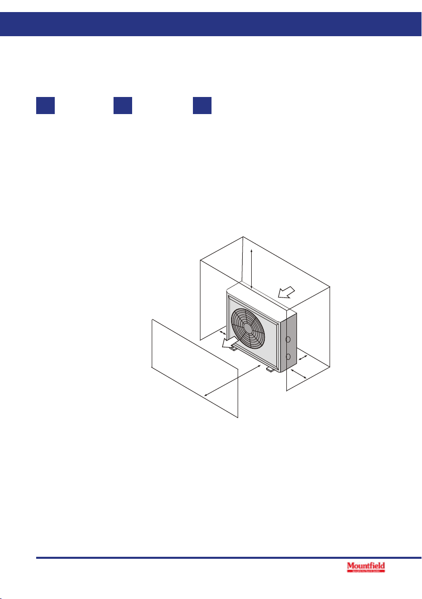
DO NOT place the unit in an enclosed area with a limited air volume, where the units
discharge air will be re-circulated.
DO NOT place the unit to shrubs which can block air inlet. These locations deny the unit of a
continuous source of fresh air which reduces it efficiency and may prevent adequate heat
delivery.
3.2 Swimming Pool Heat Pumps Location
Normally, the pool heat pump is installed within 7.5 metres of the pool. The longer the
distance from the pool, the greater the heat loss from the piping. For the most part ,the piping
is buried. Therefore, the heat loss is minimal for runs of up to15 meters(15 meters to and from
the pump = 30 meters total), unless the ground is wet or the water table is high. A very rough
estimate of heat loss per 30 meters is 0.6 kW-hour,(2000BTU) for every 5 difference in
temperature between the pool water and the ground surrounding the pipe, which translates to
about 3% to 5% increase in run time.
3.3 How Close To Your Pool?
Air inlet
Air outlet
2500mm
700mm
300mm
500mm
700mm