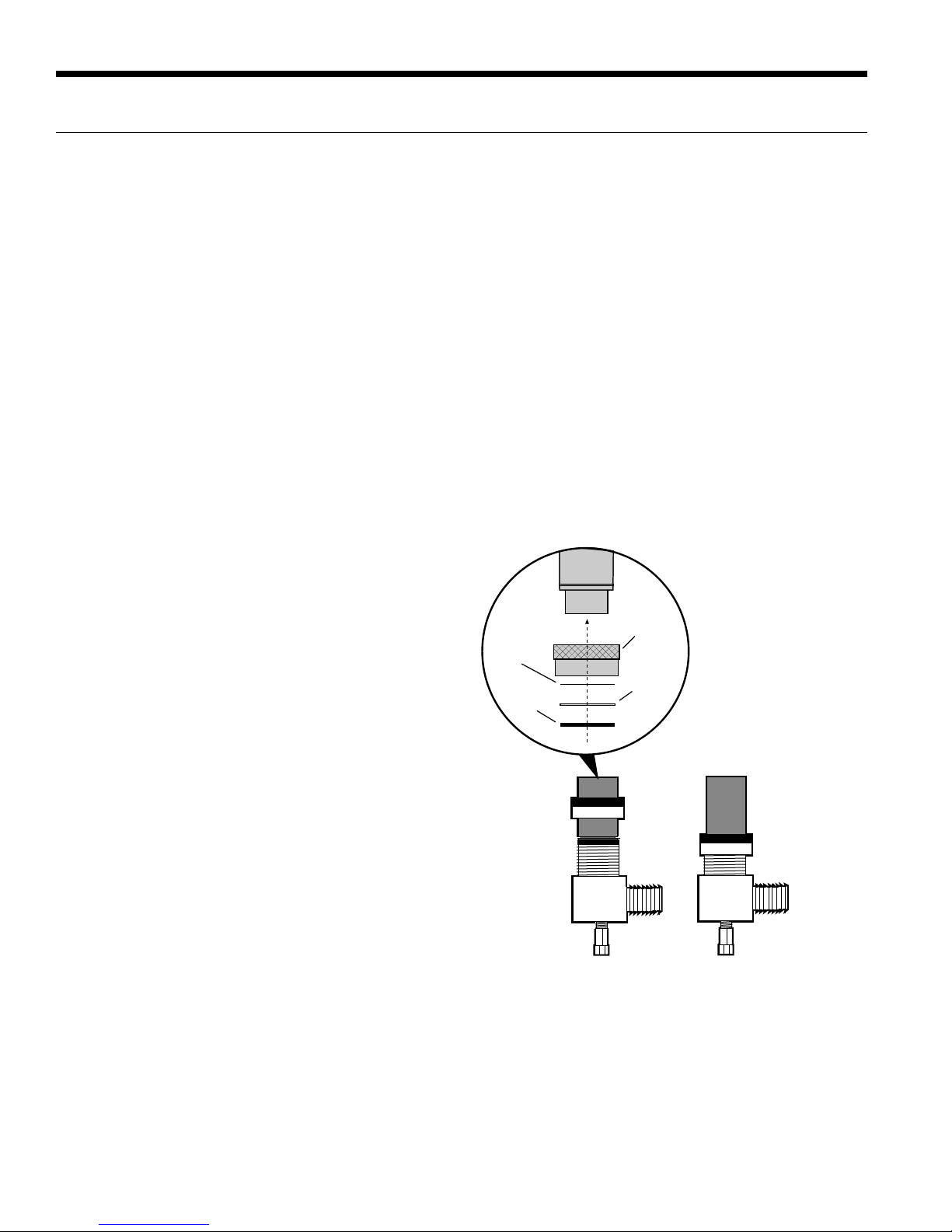
Geostar ASTON SERIES User manual

INSTALLATION MANUAL
GEOTHERMAL HEAT PUMPS
AFFORDABLE RENEWABLE CLEAN
ASTON SERIES
N


3
Table of Contents
Model Nomenclature . . . . . . . . . . . . . . . . . . . . . . . . . . . . . . . . . . . . . . . . . . . . . . . . . . . . . . . . . . . . . . . 4
General Installation Information . . . . . . . . . . . . . . . . . . . . . . . . . . . . . . . . . . . . . . . . . . . . . . . . . . . . . . . 5
Closed Loop Ground Source Systems. . . . . . . . . . . . . . . . . . . . . . . . . . . . . . . . . . . . . . . . . . . . . . . . . 10
Open Loop Ground Water Systems . . . . . . . . . . . . . . . . . . . . . . . . . . . . . . . . . . . . . . . . . . . . . . . . . . . .11
Hot Water Generator Connections. . . . . . . . . . . . . . . . . . . . . . . . . . . . . . . . . . . . . . . . . . . . . . . . . . . . 12
Electrical Connections . . . . . . . . . . . . . . . . . . . . . . . . . . . . . . . . . . . . . . . . . . . . . . . . . . . . . . . . . . . . . 14
Electronic Thermostat Installation . . . . . . . . . . . . . . . . . . . . . . . . . . . . . . . . . . . . . . . . . . . . . . . . . . . . 15
Auxiliary Heat Ratings . . . . . . . . . . . . . . . . . . . . . . . . . . . . . . . . . . . . . . . . . . . . . . . . . . . . . . . . . . . . . 16
Auxiliary Heat Electrical Data. . . . . . . . . . . . . . . . . . . . . . . . . . . . . . . . . . . . . . . . . . . . . . . . . . . . . . . . 16
Electrical Data . . . . . . . . . . . . . . . . . . . . . . . . . . . . . . . . . . . . . . . . . . . . . . . . . . . . . . . . . . . . . . . . . . . 17
Blower Performance Data . . . . . . . . . . . . . . . . . . . . . . . . . . . . . . . . . . . . . . . . . . . . . . . . . . . . . . . . . . 19
Dimensional Data. . . . . . . . . . . . . . . . . . . . . . . . . . . . . . . . . . . . . . . . . . . . . . . . . . . . . . . . . . . . . . . . . 24
Physical Data . . . . . . . . . . . . . . . . . . . . . . . . . . . . . . . . . . . . . . . . . . . . . . . . . . . . . . . . . . . . . . . . . . . . 28
The Aurora™ Control System . . . . . . . . . . . . . . . . . . . . . . . . . . . . . . . . . . . . . . . . . . . . . . . . . . . . . . . 30
Reference Calculations and Legend . . . . . . . . . . . . . . . . . . . . . . . . . . . . . . . . . . . . . . . . . . . . . . . . . . 39
Wiring Schematics . . . . . . . . . . . . . . . . . . . . . . . . . . . . . . . . . . . . . . . . . . . . . . . . . . . . . . . . . . . . . . . . 40
Unit Startup . . . . . . . . . . . . . . . . . . . . . . . . . . . . . . . . . . . . . . . . . . . . . . . . . . . . . . . . . . . . . . . . . . . . . 48
Operating Parameters . . . . . . . . . . . . . . . . . . . . . . . . . . . . . . . . . . . . . . . . . . . . . . . . . . . . . . . . . . . . . 50
Pressure Drop . . . . . . . . . . . . . . . . . . . . . . . . . . . . . . . . . . . . . . . . . . . . . . . . . . . . . . . . . . . . . . . . . . . 52
Compressor and Thermistor Resistance . . . . . . . . . . . . . . . . . . . . . . . . . . . . . . . . . . . . . . . . . . . . . . . 53
Refrigerant Circuit Guideline . . . . . . . . . . . . . . . . . . . . . . . . . . . . . . . . . . . . . . . . . . . . . . . . . . . . . . . . 53
Heat of Extraction/Rejection. . . . . . . . . . . . . . . . . . . . . . . . . . . . . . . . . . . . . . . . . . . . . . . . . . . . . . . . . 54
Troubleshooting . . . . . . . . . . . . . . . . . . . . . . . . . . . . . . . . . . . . . . . . . . . . . . . . . . . . . . . . . . . . . . . . . . 55
Preventive Maintenance. . . . . . . . . . . . . . . . . . . . . . . . . . . . . . . . . . . . . . . . . . . . . . . . . . . . . . . . . . . . 59
Replacement Procedures. . . . . . . . . . . . . . . . . . . . . . . . . . . . . . . . . . . . . . . . . . . . . . . . . . . . . . . . . . . 59
Service Parts List . . . . . . . . . . . . . . . . . . . . . . . . . . . . . . . . . . . . . . . . . . . . . . . . . . . . . . . . . . . . . . . . . 60
Revision Guide. . . . . . . . . . . . . . . . . . . . . . . . . . . . . . . . . . . . . . . . . . . . . . . . . . . . . . . . . . . . . . . . . . . 63
ASTON SERIES INSTALLATION MANUAL

4
Model Nomenclature
Model
10 = Aston
1-2 3 4 5-7 8 9 10 11 12 13 14 15 16 17
10 1 A 038 T L 1 1 1 C 0 0 A 0
Type
1 = Vertical
2 = Horizontal
Vintage
A = Current
Unit Capacity (MBTUH)
012, 018, 022, 026, 030
036, 038, 042, 048, 049
060, 064, 070, 072
Discharge Configuration
B = Bottom (Vertical 022-072)
E = End (Horizontal)
R = Rear (Vertical 042-072)
S = Side (Horizontal)
T = Top (Vertical)
Return Configuration
L = Left
R = Right
Voltage
1 = 208-230/60/1 Hot Water Generator & GeoStart Option
0 = No HWG, No GeoStart
1 = HWG with Factory Installed Pump, No GeoStart1
3 = No HWG, GeoStart2
4 = HWG with Factory Installed Pump, GeoStart1,2
Blower Option
0 = PSC
1 = ECM (018-072)
2 = High Static ECM (036-049)
3 = High Static PSC (022, 030, 036, 042, 048)
4 = 5 Speed ECM (022-072)
Coax Option
C = Copper
N = CuproNickel
Controls Option
A= Aurora Base Control (ABC)
B =Aurora Advanced Controls (AXB)
C =Aurora Performance Package (018-072)4
D =Aurora Performance & Refrigeration Package (018-072)4
Future Option
0 = Standard
Future Option
0 = Standard
Filter Option
0 = 2” MERV 11 Filter
4 =AlpinePure 411 (022-72)3
Rev.: 15 March 2012D
Notes:
1 = HWG Available 018-072
2 = GeoStart Available 018-072
3 = Available on Vertical Configurations Only (Not Available on Horizontal Models)
4 = Controls Option Not Available with PSC Motor
ASTON SERIES INSTALLATION MANUAL

5
WARNING: Before performing service or
maintenance operations on a system, turn off main
power switches to the indoor unit. If applicable, turn
off the accessory heater power switch. Electrical
shock could cause personal injury.
Installing and servicing heating and air conditioning equipment can
be hazardous due to system pressure and electrical components.
Only trained and qualified service personnel should install, repair
or service heating and air conditioning equipment. Untrained
personnel can perform the basic maintenance functions of cleaning
coils and cleaning and replacing filters. All other operations should
be performed by trained service personnel. When working on
heating and air conditioning equipment, observe precautions in
the literature, tags and labels attached to the unit and other safety
precautions that may apply.
Follow all safety codes. Wear safety glasses and work gloves.
Use a quenching cloth for brazing operations and have a fire
extinguisher available.
Moving and Storage
Move units in the normal “up” orientation. Horizontal units may
be moved and stored per the information on the packaging. Do
not stack more than three units in total height. Vertical units may
be stored one upon another to a maximum height of two units.
Do not attempt to move units while stacked. When the equipment
is received, all items should be carefully checked against the bill
of lading to be sure all crates and cartons have been received.
Examine units for shipping damage, removing the units from the
packaging if necessary. Units in question should also be internally
inspected. If any damage is noted, the carrier should make the
proper notation on the delivery receipt, acknowledging the damage.
Unit Location
Locate the unit in an indoor area that allows for easy removal of
the filter and access panels. Location should have enough space
for service personnel to perform maintenance or repair. Provide
sufficient room to make water, electrical and duct connection(s). If
the unit is located in a confined space, such as a closet, provisions
must be made for return air to freely enter the space by means of a
louvered door, etc. Any access panel screws that would be difficult to
remove after the unit is installed should be removed prior to setting
the unit. On horizontal units, allow adequate room below the unit for a
condensate drain trap and do not locate the unit above supply piping.
Care should be taken when units are located in unconditioned
spaces to prevent damage from frozen water lines and excessive
heat that could damage electrical components.
Safety Considerations
General Installation Information
Figure 1: Vertical Unit Mounting
2 in. Extruded
Polystyrene
Filter Rack Conversion
A 2 in. MERV 11 filter is shipped with the heat pump. To field
convert the filter rack to use 1 in. filters, simply insert the provided
plastic push pins into the holes located in the filter rack. There are
holes on the top and bottom of the rack, underneath the instruction
labels, for field conversion to 1 in. filters.
Installing Vertical Units
Prior to setting the unit in place, remove and discard the
compressor hold down shipping bolt located at the front of the
compressor mounting bracket.
Vertical units are available in left or right air return configurations.
Top and rear air discharge vertical units should be mounted level
on a vibration absorbing pad slightly larger than the base to
provide isolation between the unit and the floor. It is not necessary
to anchor the unit to the floor (see below).
Bottomflow units should be mounted level and sealed well to floor
to prevent air leakage. Bottomflow units require the supply air
opening to be cut at least 1/2 in. larger than the unit’s air outlet.
Protect the edges of combustible flooring with sheet metal over-
wrap or other non-combustible material.
Unit Mounti
ng
ASTON SERIES INSTALLATION MANUAL

6
CAUTION: Do not use rods smaller than 3/8-inch
diameter since they may not be strong enough
to support the unit. The rods must be securely
anchored to the ceiling.
General Installation Information cont.
Figure 2: Horizontal Unit Mounting
Installing Horizontal Units
Remove and discard the compressor hold down shipping bolt
located at the front of the compressor mounting bracket prior to
setting the unit in place. Horizontal units are available with side
or end discharge. Horizontal units are normally suspended from a
ceiling by four or six 3/8 in. diameter threaded rods. The rods are
usually attached to the unit by hanger bracket kits furnished with
each unit.
Lay out the threaded rods per the dimensions in Figure 3.
Assemble the hangers to the unit as shown. Securely tighten the
brackets to the unit using the weld nuts located on the underside of
the bottom panel. When attaching the hanger rods to the bracket, a
double nut is required since vibration could loosen a single nut. To
allow filter access, one bracket on the filter side should be installed
180° from the position shown in Figure 3. The unit should be
pitched approximately 1/4-inch towards the drain in both directions
to facilitate the removal of condensate. Use only the bolts provided
in the kit to attach hanger brackets. The use of longer bolts could
damage internal parts.
Some residential applications require the installation of horizontal
units on an attic floor. In this case, the unit should be set in a full
size secondary drain pan on top of a vibration absorbing pad. The
secondary drain pan prevents possible condensate overflow or
water leakage damage to the ceiling. The secondary drain pan is
usually placed on a plywood base isolated from the ceiling joists by
additional layers of vibration absorbing material.
Insulate supply
plenum and use
at least one 90
elbow to
reduce noise
Electrical
Disconnect
Flexible Duct
Collar Threaded Rods
Line Voltage
Ball Valves
Hose
Kits
To Line
Power
To
Thermostat
Hanging
Brackets
(Included)
Building Water Loop
O
ASTON SERIES INSTALLATION MANUAL

7
General Installation Information cont.
:STb@WUVb
!&BV`SORSR
@]RPg]bVS`a
6Sf<cba
Pg]bVS`a
EOaVS`
DWP`ObW]\
7a]ZOb]`
0]ZbO\R
:]QYEOaVS`
1
4/
/W`1]WZ
2
0
/W`1]WZ
!
"
"
!
Hanger Dimensions
Model Hanger Kit
Part Number Unit Hanger Dimensions
ABCD
Single Speed
012 in. 99S500A04 44.7 25.1 21.4 n/a
cm. 113.5 63.8 54.4 n/a
018 in. 99S500A04 53.7 25.1 21.4 n/a
cm. 136.4 63.8 54.4 n/a
022-030 in. 99S500A04 63.4 24.8 21.1 n/a
cm. 161.0 63.0 53.6 n/a
036 in. 99S500A03 72.4 27.8 24.1 29.3
cm. 183.9 70.6 61.2 74.4
042-048 in. 99S500A03 77.4 27.8 24.1 29.3
cm. 196.6 70.6 61.2 74.4
060-070 in. 99S500A03 82.4 27.8 24.1 29.3
cm. 209.3 70.6 61.2 74.4
Dual Capacity
026 in. 99S500A04 63.4 24.8 21.1 n/a
cm. 161.0 63.0 53.6 n/a
038 in. 99S500A03 72.4 27.8 24.1 29.3
cm. 183.9 70.6 61.2 74.4
049 in. 99S500A03 77.4 27.8 24.1 29.3
cm. 196.6 70.6 61.2 74.4
064 in. 99S500A03 82.4 27.8 24.1 29.3
cm. 209.3 70.6 61.2 74.4
072 in. 99S500A03 82.4 27.8 24.1 29.3
cm. 209.3 70.6 61.2 74.4
2/8/12
Weight Distribution
Model Vertical
Weight Horizontal
Weight
Horizontal Weight Distribution
Front Back
1234
Single Speed
012 185 185 70 45 45 25
[84] [84] [32] [20] [20] [11]
018 220 220 84 44 59 33
[100] [100] [38] [20] [27] [15]
022 313 320 122 64 86 48
[142] [145] [55] [29] [39] [22]
030 328 335 130 42 105 59
[149] [152] [59] [19] [47] [27]
036 373 388 147 94 94 52
[169] [176] [67] [43] [43] [24]
042 388 423 161 56 130 76
[176] [192] [73] [25] [59] [35]
048 428 438 136 114 123 66
[194] [199] [62] [52] [56] [30]
060 463 473 147 123 132 71
[210] [214] [67] [56] [60] [32]
070 488 498 154 129 139 75
[221] [226] [70] [59] [63] [34]
Dual Capacity
026 313 320 121 78 78 43
[142] [145] [55] [35] [35] [20]
038 378 388 147 94 94 52
[171] [176] [67] [43] [43] [24]
049 428 438 136 114 123 66
[194] [199] [62] [52] [56] [30]
064 473 483 150 126 135 72
[214] [219] [68] [57] [61] [33]
072 488 500 155 130 140 75
[221] [226] [70] [59] [64] [34]
Weights are listed in lbs. [kg] 2/29/12
Figure 3: Hanger Location and Assembly
ASTON SERIES INSTALLATION MANUAL

8
the swivel connector and thread the female locking ring onto the
pipe threads, while maintaining the brass connector in the desired
direction. Tighten the connectors by hand, then gently snug the
fitting with pliers to provide a leak-proof joint. When connecting
to an open loop (ground water) system, thread any 1-inch MPT
fitting (SCH80 PVC or copper) into the swivel connector and
tighten in the same manner as noted above. The open and closed
loop piping system should include pressure/temperature taps for
serviceability.
Never use flexible hoses smaller than 1-inch inside diameter
on the unit. Limit hose length to 10 feet per connection. Check
carefully for water leaks.
Duct System
An air outlet collar is provided on vertical top and rear air discharge
units and all horizontal units to facilitate a duct connection
(vertical bottomflow units have no collar). A flexible connector
is recommended for discharge and return air duct connections
on metal duct systems. Uninsulated duct should be insulated
with a minimum of 1-inch duct insulation. Application of the
unit to uninsulated ductwork in an unconditioned space is not
recommended as the unit’s performance will be adversely affected.
If the unit is connected to existing ductwork, check the duct
system to ensure that it has the capacity to accommodate the air
required for the unit application. If the duct is too small, as in the
replacement of heating only systems, larger ductwork should be
installed. All existing ductwork should be checked for leaks and
repaired if necessary.
The duct system should be sized to handle the design airflow
quietly and efficiently. To maximize sound attenuation of the unit
blower, the supply and return plenums should include an internal
duct liner of fiberglass or constructed of ductboard for the first few
feet. On systems employing a sheet metal duct system, canvas
connectors should be used between the unit and the ductwork. If
air noise or excessive airflow is a problem, the blower speed can
be changed.
Water Piping
The proper water flow must be provided to each unit whenever the
unit operates. To assure proper flow, use pressure/temperature
ports to determine the flow rate. These ports should be located at
the supply and return water connections on the unit. The proper
flow rate cannot be accurately set without measuring the water
pressure drop through the refrigerant-to-water heat exchanger.
All source water connections on residential units are swivel piping
fittings (see Figure 4) that accept a 1-inch male pipe thread (MPT).
The swivel connector has a rubber gasket seal similar to a rubber
hose gasket, which when mated to the flush end of any 1-inch
threaded pipe provides a leak-free seal without the need for thread
sealing tape or compound. Check to ensure that the rubber seal
is in the swivel connector prior to attempting any connection. The
rubber seals are shipped attached to the waterline. To make the
connection to a ground loop system, mate the brass connector
(supplied in CK4LI connector kit) against the rubber gasket in
Figure 4: Swivel Connections
Locking
Ring
Stainless
Steel
Snap Ring
Gasket
Support
Sleeve
Gasket
Material
General Installation Information cont.
ASTON SERIES INSTALLATION MANUAL

9
1/2'' Pitch
Drain
1.5 in. 1.5 in.
PVC tube stub
PVC coupling Vent (if needed)
PVC tube stub
1/8 in. per foot
NOTE: Check dimensional data for actual PVC sizes.
Figure 6: Unit Pitch for Drain
Figure 5: Horizontal Drain Connection
Low Water Coil Limit
Set the freeze sensing switch SW2-1 on the Aurora Base Control
(ABC) printed circuit board for applications using a closed loop
antifreeze solution to “LOOP” (15°F). On applications using an
open loop/ground water system (or closed loop no antifreeze), set
this dip switch to “WELL” (30°F), the factory default setting. (Refer
to the DIP Switch Settings table in theAurora Control section.)
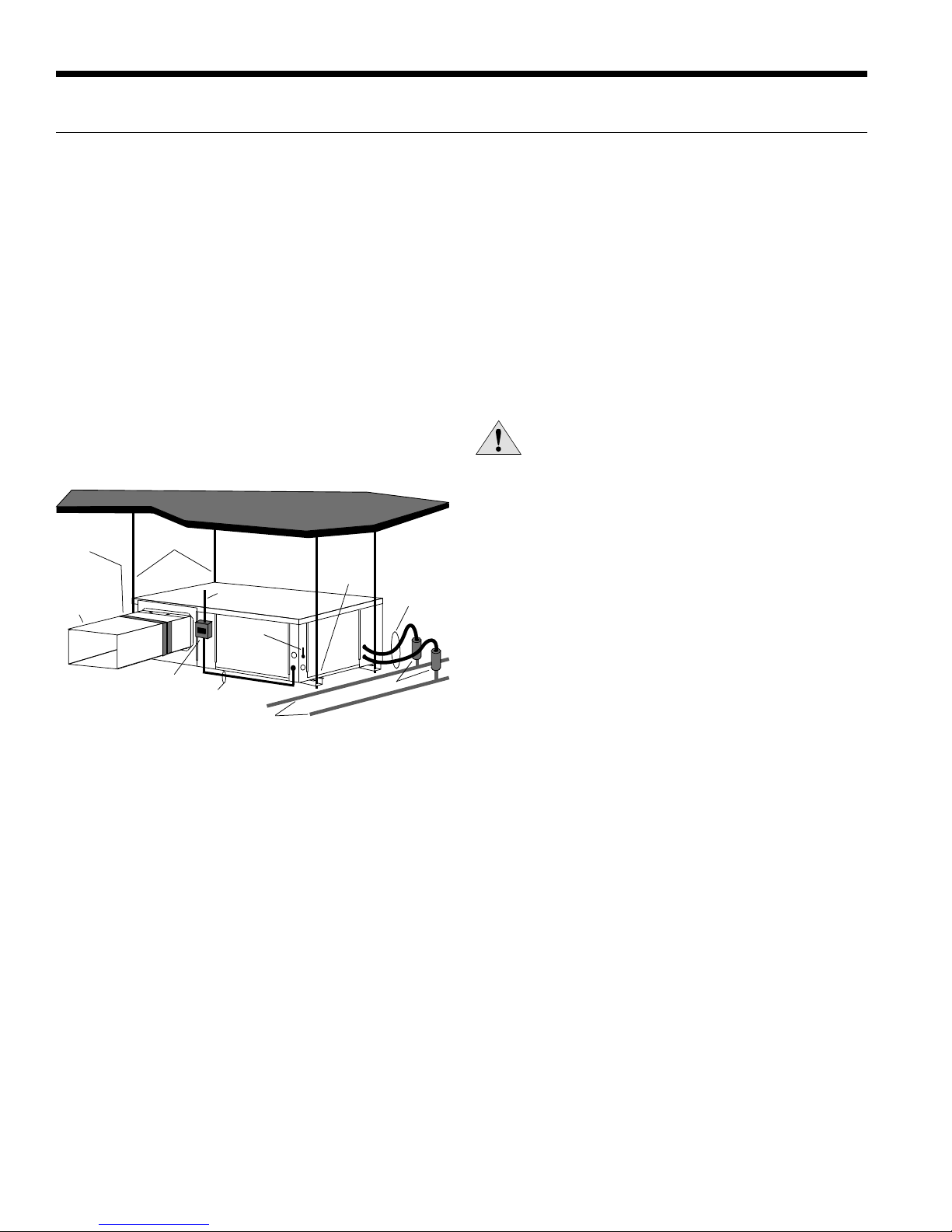
Condensate Drain
On vertical units, the internal condensate drain assembly consists
of a drain tube which is connected to the drain pan, a 3/4-inch PVC
female adapter and a flexible connecting hose. The female adapter
may exit either the front or the side of the cabinet. The adapter
should be glued to the field-installed PVC condensate piping.
On vertical units, a condensate hose is inside all cabinets as a
trapping loop; therefore, an external trap is not necessary.
On horizontal units, a PVC stub is provided for condensate drain
piping connection. An external trap is required (see below). If a
vent is necessary, an open stand pipe may be applied to a tee in
the field-installed condensate piping.
Water Quality
In ground water situations where scaling could be heavy or where
biological growth such as iron bacteria will be present, a closed
loop system is recommended. The heat exchanger coils in ground
water systems may, over a period of time, lose heat exchange
capabilities due to a buildup of mineral deposits inside. These
can be cleaned, but only by a qualified service mechanic, as
special solutions and pumping equipment are required. Hot water
generator coils can likewise become scaled and possibly plugged.
In areas with extremely hard water, the owner should be informed
that the heat exchanger may require occasional flushing.
Units with cupronickel heat exchangers are recommended for
open loop applications due to the increased resistance to build-up
and corrosion, along with reduced wear caused by acid cleaning.
Failure to adhere to the guidelines in the water quality table could
result in the loss of warranty.
General Installation Information cont.
Material Copper 90/10 Cupronickel 316 Stainless Steel
pH Acidity/Alkalinity 7 - 9 7 - 9 7 - 9
Scaling Calcium and
Magnesium Carbonate (Total Hardness)
less than 350 ppm (Total Hardness)
less than 350 ppm
Corrosion
Hydrogen Sulfide Less than 0.5 ppm (rotten egg
smell appears at 0.5 ppm) 10 - 50 ppm Less than 1 ppm
Sulfates Less than 125 ppm Less than 125 ppm Less than 200 ppm
Chlorine Less than 0.5 ppm Less than 0.5 ppm Less than 0.5 ppm
Chlorides Less than 20 ppm Less than 125 ppm Less than 300 ppm
Carbon Dioxide Less than 50 ppm 10 - 50 ppm 10 - 50 ppm
Ammonia Less than 2 ppm Less than 2 ppm Less than 20 ppm
Ammonia Chloride Less than 0.5 ppm Less than 0.5 ppm Less than 0.5 ppm
Ammonia Nitrate Less than 0.5 ppm Less than 0.5 ppm Less than 0.5 ppm
Ammonia Hydroxide Less than 0.5 ppm Less than 0.5 ppm Less than 0.5 ppm
Ammonia Sulfate Less than 0.5 ppm Less than 0.5 ppm Less than 0.5 ppm
Total Dissolved Solids (TDS) Less than 1000 ppm 1000 - 1500 ppm 1000 - 1500 ppm
LSI Index +0.5 to -0.5 +0.5 to -0.5 +0.5 to -0.5
Iron Fouling
(Biological Growth)
Iron, FE2+ (Ferrous)
Bacterial Iron Potential < 0.2 ppm < 0.2 ppm < 0.2 ppm
Iron Oxide Less than 1 ppm, above this level
deposition will occur Less than 1 ppm, above this level
deposition will occur
Erosion Suspended Solids Less than 10 ppm and filtered for
max. of 600 micron size Less than 10 ppm and filtered for
max. of 600 micron size
Threshold Velocity
(Fresh Water) < 6 ft/sec < 6 ft/sec < 6 ft/sec
NOTES: Grains = ppm divided by 17
mg/L is equivalent to ppm 2/22/12
ASTON SERIES INSTALLATION MANUAL

10
Figure 7: Closed Loop Ground Source Application
NOTE: For closed loop systems with antifreeze protection, set
SW2-1 to the “LOOP” (15°F) position. (Refer to the DIP Switch
Settings table in the Aurora Control section.)
Once piping is completed between the unit, pumps and the ground
loop (see figure below), final purging and charging of the loop is
required. A flush cart (or a 1.5 HP pump minimum) is needed to
achieve adequate flow velocity in the loop to purge air and dirt
particles from the loop itself. Antifreeze solution is used in most
areas to prevent freezing. Flush the system adequately to remove
as much air as possible then pressurize the loop to a static pressure
of 40-50 psi (summer) or 50-75 psi (winter). This is normally
adequate for good system operation. Loop static pressure will
fluctuate with the seasons. Pressures will be higher in the winter
months than during the cooling season. This fluctuation is normal
and should be considered when initially charging the system.
After pressurization, be sure to turn the venting (burping) screw in the
center of the pump two (2) turns open (water will drip out), wait until
all air is purged from the pump, then tighten the plug. Ensure that the
loop pumps provide adequate flow through the unit(s) by checking the
pressure drop across the heat exchanger and comparing it to the unit
capacity data in this catalog. 2.5 to 3 gpm of flow per ton of cooling
capacity is recommended in earth loop applications.
NOTE: Additional information can be found in Flow Center
installation manual and Flush Cart manual.
Closed Loop Ground Source Systems
Figure 8b: Primary/Secondary Hook-up
Aston “10” Series to
Electromechanical Units
ToElectromechanical Unit
CS
Aston “10” Series
to GT/GS Units
Aston Series Unit #1
with AXB Board Aston Series Unit #1
with AXB Board
Aston “10” Series
Unit #2
with AXB Board
Aston “10” Series
to Aston “10”
Series Units
VSSLOSLI OUTIN C C
VSSLOSLI OUTIN C C
With pump
wired to
Unit 2
With pump
wired to Unit 1
VSSLOSLI OUTIN C C
Shut
Down CC
SL1
In SL1
Out
GT/GS Unit #2
With pump
wired to
Unit 1
With pump
wired to
Unit 2
VSSLOSLI OUTIN C C
Figure 8a: Primary/Secondary Wiring with Aurora Base
Control (no AXB Board)
CC
T2 T1
Compressor
C
R
S
Blue
L1
L2
Black
Red
Tan(6)
Cap
Ext Pump
1/2 hp Total
208-230/60/1
Pump
G
1
2
PB1
1
2
Pump
Circuit
Breaker
Circuit
Breaker
1
5A
5A
Optional Internal
HWG Pump
HWG
Pump
Purple
Hot Water
Limit Switch
130°F
Blue
12
3
Cabinet
HW Switch
Field Supplied
Relay for Heat
Pump 1
Field Supplied
Relay for Heat
Pump 2
Heat Pump 1
Contactor Coil
Heat Pump 2
Contactor Coil
Field Supplied
Fuses 5A
Multiple Units on One Flow Center
NOTE: This feature is only available in the Aurora Advanced
Control package (AXB board), NOT theAurora Base Control (ABC).
When two units are connected to one loop pumping system, pump
control is automatically achieved by connecting the SL terminals on
connector P2 in both units with 2-wire thermostat wire. These terminals
are polarity dependant (see Figure 8b). The loop pump(s) may be
powered from either unit, whichever is more convenient. If either unit
calls, the loop pump(s) will automatically start. The use of two units on
one flow center is generally limited to a total of 20 gpm capacity.
NOTE: To achieve this same feature when heat pumps have only
the Aurora Base Control, follow Figure 8a. Installer will be required
to supply fuses, two relays, and wiring.
Variable Speed Pump Setup
When using a variable speed pump flow center (FCV1-GL or FCV2-
GL) the use of an AID Tool will be necessary to adjust minimum
and maximum flow rates. The factory default is: minimum=75% and
maximum=100% speed levels.
Flexible Duct
Collar
Vibration Absorbing Pad
P/T Plugs
Drain
Desuperheater
Connections
Auxiliary
Heater
Knockout
Low
Voltage to
Thermostat
Unit Supply
Auxiliary Heat
Supply
Insulated piping
or hose kit
Disconnects
(If Applicable)
Unit Power
P/T
TO
LOOP
GeoLink
®
Flow
Center
GeoLink®
Polyethylene w/
Armaflex®
Insulation
ASTON SERIES INSTALLATION MANUAL

11
Typical open loop piping is shown below. Always maintain
water pressure in the heat exchanger by placing water control
valves at the outlet of the unit to prevent mineral precipitation.
Use a closed, bladder-type expansion tank to minimize mineral
formation due to air exposure. Ensure proper water flow through
the unit by checking pressure drop across the heat exchanger
and comparing it to the figures in unit capacity data tables in the
specification catalog. 1.5-2 gpm of flow per ton of cooling capacity
is recommended in open loop applications.
Discharge water from the unit is not contaminated in any manner
and can be disposed of in various ways, depending on local codes,
i.e. recharge well, storm sewer, drain field, adjacent stream or
Figure 9b: Open Loop Solenoid Valve Connection Option
Typical slow operating external 24V water solenoid valve
(type VM) wiring and one (1) quick operating valve.
Figure 9a: Open Loop Solenoid Valve Connection Option
Typical quick operating external 24V water solenoid valve
(type PPV100 or BPV100) wiring.
Figure 10: Open System - Groundwater Application
NOTE: SW2-4 and SW2-5 should be “OFF” to cycle with
the compressor.
Open Loop Ground Water Systems
pond, etc. Most local codes forbid the use of sanitary sewer for
disposal. Consult your local building and zoning departments to
assure compliance in your area.
NOTE: For open loop/groundwater systems or systems that do not
contain an antifreeze solution, set SW2-Switch #1 to the “WELL”
(30°F) position. (Refer to the DIP Switch Settings table in the
Aurora Control section.) Slow opening/closing solenoid valves
(type VM) are recommended to eliminate water hammer.
Acc Com
Acc NC
Acc NO
1
2
3
C
RP1
P2
SV
Solenoid
Valve
C
R
Acc Com
ACC NC
Acc NO
VM Valve
NOTE: SW2-4 should be “ON” and SW2-5 should be “OFF” when
using a slow opening (VM) water valve.
Figure 9c: Modulating Water Valve Connection Option
Typical 0-10VDC modulating water valve.
VS PUMP
GND
24 VAC
0-10DC
1
2
3R
C
ABC BOARD
AXB BOARD
2 1
Flexible
Duct Collar
Vibration
Absorbing Pad
P/T Plugs
Drain
Desuperheater
Connections
Auxiliary
Heater
Knockout
Low Voltage
to Thermostat
and Valve
Unit Supply
Aux. Heat Supply
Water Out
Water In
Shut Off Valves
Boiler Drains
For HX Flushing
Disconnects
(IfApplicable)
Rubber Bladder
Expansion Tank
Solenoid
Valve
Shut Off Valves
(to isolate solenoid
valve while acid flushing)
Strainer
Flow Control
Valve
(on outlet of
Solenoid Valve)
Compressor
Line Voltage
ASTON SERIES INSTALLATION MANUAL

12
Figure 11: Typical Hot Water Generator Installation
Figure 12: Hot Water Generator Installation In Preheat Tank
NOTE: This configuration maximizes hot water generator capability.
Hot Water Generator Connections
In
Ball Valve
3/4 in. x 3/4 in. x 1/2 in. Tee Cold
Water In Hot
Water Out
P/T Relief
Valve
P/T Relief
Valve
HWG
Water In
HWG
Water Out
Drain ValveDrain Valve
Vent
Storage Tank Electric Powered
Water Heater
Drain Valve
In
P/T Relief
Valve
Cold
Water In Hot
Water Out
HWG
Water In
HWG
Water Out
Venting Waste
Valve or Vent
Coupling
3/4 x 3/4 x 1/2 tee
To maximize the benefits of the hot water generator a minimum
50-gallon water heater is recommended For higher demand
applications, use an 80-gallon water heater or two 50-gallon water
heaters connected in a series as shown below. Two tanks plumbed
in a series is recommended to maximize the hot water generator
capability. Electric water heaters are recommended. Make sure
all local electrical and plumbing codes are met for installing a hot
water generator. Residential units with hot water generators contain
an internal circulator and fittings. A water softener is recommended
with hard water (greater than 10 grains or 170 total hardness).
NOTES: 1) Using a preheat tank, as shown in Figure 12, will
maximize hot water generator capabilities. 2) The hot water
generator coil is constructed of vented double wall copper suitable
for potable water.
CAUTION: Elements will burn out if energized dry.
Water Tank Preparation
To install a unit with a hot water generator, follow these
installation guidelines.
1. Turn off the power to the water heater.
2. Attach a water hose to the water tank drain connection and run
the other end of the hose to an open drain or outdoors.
3. Close the cold water inlet valve to the water heater tank.
4. Drain the tank by opening the valve on the bottom of the tank,
then open the pressure relief valve or hot water faucet.
5. Flush the tank by opening the cold water inlet valve to the water
heater to free the tank of sediments. Close when draining water
is clear.
6. Disconnect the garden hose and remove the drain valve from
the water heater.
7. Refer to Plumbing Installation and Hot Water Generator Startup.
ASTON SERIES INSTALLATION MANUAL

13
Hot Water Generator Connections cont.
Hot Water Generator Startup
1. Turn the hot water generator switch to the “ON” position. The hot
water generator switch will allow the hot water generator pump to
be enabled or disabled by the service technician or homeowner.
2. Close the drain valve to the water heater.
3. Open the cold water supply to the tank.
4. Open a hot water faucet in the building to bleed air from the
system. Close when full.
5. Open the pressure relief valve to bleed any remaining air from
the tank, then close.
6. If so equipped, turn the venting (burping) screw in the center
of the pump two (2) turns open (water will drip out), wait until
all air is purged from the pump, then tighten the plug. Use vent
couplings to bleed air from the lines.
7. Carefully inspect all plumbing for water leaks and correct
as required.
8. Before restoring electrical supply to the water heater, adjust the
temperature setting on the tank.
• On tanks with both upper and lower elements, the
lower element should be turned down to the lowest
setting, approximately 100°F. The upper element
should be adjusted to 120°F to 130°F. Depending upon
the specific needs of the customer, you may want to
adjust the upper element differently.
• On tanks with a single element, lower the thermostat
setting to 120°F.
9. After the thermostat(s) is adjusted, replace the access cover
and restore electrical supply to the water heater.
10.Make sure that any valves in the hot water generator water
circulating circuit are open.
11.Turn on the unit to first stage heating.
12.Use an AID Tool to enable HWG and select the desired water
heating set point. Selectable set points are 100°F – 140°F in
5°F increments (default 130°F). From the Main Menu of the AID
Tool select Setup, then AXB Setup.
13.The hot water generator pump should be running. When
the pump is first started, turn the venting (burping) screw (if
equipped) in the center of the pump two (2) turns open until
water dribbles out, then replace. Allow the pump to run for at
least five minutes to ensure that water has filled the circulator
properly. Be sure the switch for the hot water generator pump
switch is “ON”.
14.The temperature difference between the water entering and
leaving the hot water generator should be 5°F to 15°F. The
water flow should be approximately 0.4 gpm per ton of
nominal cooling.
15.Allow the unit to heat water for 15 to 20 minutes to be sure
operation is normal.
Plumbing Installation
1. Inspect the dip tube in the water heater cold inlet for a check
valve. If a check valve is present it must be removed or
damage to the hot water generator circulator will occur.
2. Remove drain valve and fitting.
3. Thread the 3/4-inch NPT x 3-1/2-inch brass nipple into the
water heater drain port.
4. Attach the center port of the 3/4-inch FPT tee to the opposite
end of the brass nipple.
5. Attach the 1/2-inch copper to 3/4-inch NPT adaptor to the side
of the tee closest to the unit.
6. Install the drain valve on the tee opposite the adaptor.
7. Run interconnecting tubing from the tee to hot water generator
water out.
8. Cut the cold water “IN” line going to the water heater.
9. Insert the reducing solder tee in line with cold water “IN” line
as shown.
10.Run interconnecting copper tubing between the unit hot water
generator water “IN” and the tee (1/2-inch nominal). The
recommended maximum distance is 50 feet.
11.To prevent air entrapment in the system, install a vent coupling
at the highest point of the interconnecting lines.
12.Insulate all exposed surfaces of both connecting water lines
with 3/8-inch wall closed cell insulation.
NOTE: All plumbing and piping connections must comply with local
plumbing codes.
CAUTION: Never operate the HWG circulating pump
while dry. If the unit is placed in operation before
the hot water generator piping is connected, be sure
that the pump switch is set to the OFF position.
Hot Water Generator Switch
The hot water generator switch is taped in the disabled position
at the factory.
ASTON SERIES INSTALLATION MANUAL

14
General
Be sure the available power is the same voltage and phase as that
shown on the unit serial plate. Line and low voltage wiring must be
done in accordance with local codes or the National Electric Code,
whichever is applicable.
Unit Power Connection
Connect the incoming line voltage wires to L1 and L2 of the
contactor as shown in Figure 13B for single-phase unit. Consult
the Unit Electrical Data in this manual for correct fuse sizes.
Open lower front access panel. Insert power wires through
knockouts on lower left side of cabinet. Route wires through left side
of control box and connect to contactor and ground (Figure 13B).
Accessory Relay
A set of “dry” contacts has been provided to control accessory
devices, such as water solenoid valves on open loop installations,
electronic air cleaners, humidifiers, etc. This relay contact should
be used only with 24 volt signals and not line voltage power. The
Wire Insert
Location
Figure 13B:
Line Voltage 208-230/60/1 control box
Figure 13A:
Wire access
Electrical Connections
relay has both normally open and normally closed contacts and
can operate with either the fan or the compressor. Use DIP switch
SW2-4 and 5 to cycle the relay with blower, compressor, or control
a slow opening water valve. The relay contacts are available on
terminals #2 and #3 of P2.
A second configurable accessory relay is provided on the AXB
board, if installed. When powering high VA draw components such
as electronic air cleaners or VM type open loop water valves,
R should be taken ‘pre-fuse’ from the ‘R’ quick connect on the
ABC board and not the ‘post-fuse’ ‘R’ terminal on the thermostat
connection. If not, blown ABC fuses might result.
208 Volt Operation
All 208/230 units are factory wired for 230 volt operation. For
208 volt operation, the red and blue transformer wires must be
switched on terminal strip PB2.
L1
L2
PB1
1
2
1
2
3
T1T2
PS
ASTON SERIES INSTALLATION MANUAL

15
R
Y1
C
W
O
G
L
24VAC (Hot)
24VAC (Common)
Compressor (1st Stage)
Aux. Heat
Reversing Valve
Blower Relay
System Monitor
Microprocessor Controller
Thermostat Connection
Y2
Compressor (2nd Stage)
Electronic Thermostat Installation
Position the thermostat subbase against the wall so that it is
level and the thermostat wires protrude through the middle of the
subbase. Mark the position of the subbase mounting holes and
drill holes with a 3/16-inch bit. Install supplied anchors and secure
base to the wall. Thermostat wire must be 8-conductor (4 or 5
counductor for communicating thermostats), 20-AWG (minimum)
wire. Strip the wires back 1/4-inch (longer strip lengths may
cause shorts) and insert the thermostat wires into the connector
as shown. Tighten the screws to ensure secure connections.
The thermostat has the same type connectors, requiring the
same wiring. See instructions enclosed in the thermostat for
detailed installation and operation information. The W1 terminal
on TPCM32U03GSR and TPCM32U04GSR communicating
thermostats may be hard wired to provide aux/emergency heat in
the event communication is lost between the thermostat and the
ABC microprocessor.
NOTE: Aurora Base Control (ABC) DIP switch SW2-7 is
required to be in the “OFF” position for the control to operate
with FaultFlash or ComforTalk thermostats. SW2-7 in the “ON”
position configures the control to operate with typical thermostats
(continuous lockout signal). There must be a wire connecting
Y2 on the Aurora controller to 2nd stage compressor on the
thermostat for proper operation. SW2-7 DIP switch position is not
relevant with communicating thermostats.
Figure 15a: Thermostat Wiring (Y1 Style Signals)
C
P7
P1
–
R
W
C 24VAC (Common)
R 24VAC (Hot)
B- Communication
W1 (Optional)
Microprocessor Controller
Thermostat Connection
+A+ Communication
TPCM32U03GSR/TPCM32U04GSR
Monochrome Thermostats
C
P7
–
R
C 24VAC (Common)
R 24VAC (Hot)
DX- Communication
Microprocessor
Controller
Thermostat
Connection
+DX+ Communication
TPCC32U01GSR
Color Touchscreen
Thermostat
Figure 15b: Thermostat Wiring (Communicating Style Signals)
Pump Power Wiring
See Figure 14 for electrical connections from control box to pumps.
FC1/FC2 style flow centers with fixed speed pumps connect to
PB1 in the control box. If using a variable speed pump it should be
connected to L1 and L2 on the AXB.
Figure 14: Pump Wiring 208-230/60/1
Electrical Connections cont.
External
Loop Pump(s)
208-230/60/1
1/2 hp Max
PB1
CB
Optional External
Variable Speed Loop
Pump (ex. Magna Geo)
208-230/60/1
ASTON SERIES INSTALLATION MANUAL

16
Auxiliary Heat Ratings
Auxiliary Heat Electrical Data
Model Supply
Circuit Heater Amps Min Circuit Amp Fuse (USA) Fuse (CAN) CKT BRK
208 V 240 V 208 V 240 V 208 V 240 V 208 V 240 V 208 V 240 V
EAS(H)4 Single 13.7 15.8 17.9 20.5 20 20 20 20 20 20
EAM(H)5 Single 17.3 20.0 26.7 30.0 30 30 30 30 30 30
EAM(H)8 Single 27.5 31.7 39.3 44.6 40 45 40 45 40 45
EAM(H)10 Single 34.7 40.0 48.3 55.0 50 60 50 60 50 60
EAL(H)10 Single 34.7 40.0 53.3 60.0 60 60 60 60 60 60
EAL(H)15
Single 52.0 60.0 75.0 85.0 80 90 80 90 70 100
L1/L2 34.7 40.0 53.3 60.0 60 60 60 60 60 60
L3/L4 17.3 20.0 21.7 25.0 25 25 25 25 20 30
EAL(H)20
Single 69.3 80.0 96.7 110.0 100 110 100 110 100 100
L1/L2 34.7 40.0 53.3 60.0 60 60 60 60 60 60
L3/L4 34.7 40.0 43.3 50.0 45 50 45 50 40 50
All heaters rated single phase 60 cycle and include unit blower load
All fuses type “D” time delay (or HACR circuit breaker in USA)
Supply wire size to be determined by local codes
2/11/12
Model kW Stages Btu/h Min cfm Model Size Compatibility
208V 230V 208V 230V 012 018 022 026 - 030 036 - 042 048 - 072
EAS(H)4 2.9 3.8 1 9,700 12,900 250 •
EAM(H)5 3.6 4.8 1 12,300 16,300 450 •••
EAM(H)8 5.7 7.6 2 19,400 25,900 550 •••
EAM(H)10 7.2 9.6 2 24,600 32,700 650 •
EAL(H)10 7.2 9.6 2 24,600 32,700 1100 ••
EAL(H)15 10.8 14.4 3 36,900 49,100 1250 ••
EAL(H)20 14.4 19.2 4 49,200 65,500 1500 •
Order the “H” part number when installed on horizontal and vertical rear discharge units
Air flow level for auxiliary heat (Aux) must be above the minimum cfm in this table 5/8/12
ASTON SERIES INSTALLATION MANUAL

17
Electrical Data
* With optional 1 hp ECM motor
** With optional GeoStart®
Rated voltage of 208/230/60/1
A
ll fuses Class RK-5
HACR circuit breaker in USA only
Single Speed Unit with Variable Speed ECM Motor
Model Rated Voltage Voltage
Min/Max
Compressor HWG
Pump FLA
Ext
Loop
FLA
Blower
Motor FLA
Total
Unit
FLA
Min
Circ
Amp
Max
Fuse/
HACR
MCC RLA LRA LRA**
018 208-230/60/1 197/253 10.4 6.7 33.5 12.0 0.4 5.4 4.0 16.5 18.1 20
022 208-230/60/1 197/253 14.0 9.0 48.0 17.0 0.4 5.4 4.0 18.8 21.0 30
030 208-230/60/1 197/253 20.0 12.8 58.3 21.0 0.4 5.4 4.0 22.6 25.8 35
036 208-230/60/1 197/253 22.0 14.1 73.0 26.0 0.4 5.4 4.0 23.9 27.4 40
036* 208-230/60/1 197/253 22.0 14.1 73.0 26.0 0.4 5.4 7.0 26.9 30.4 40
042 208-230/60/1 197/253 26.0 16.6 79.0 28.0 0.4 5.4 4.0 26.4 30.6 45
042* 208-230/60/1 197/253 26.0 16.6 79.0 28.0 0.4 5.4 7.0 29.4 33.6 50
048 208-230/60/1 197/253 31.0 19.8 109.0 38.0 0.4 5.4 4.0 29.6 34.6 50
048* 208-230/60/1 197/253 31.0 19.8 109.0 38.0 0.4 5.4 7.0 32.6 37.6 50
060 208-230/60/1 197/253 41.2 26.4 134.0 47.0 0.4 5.4 7.0 39.2 45.8 70
070 208-230/60/1 197/253 44.2 28.3 178.0 63.0 0.4 5.4 7.0 41.1 48.2 70
9/27/12
Single Speed Unit with 5-Speed ECM Motor
Model Rated
Voltage Voltage
Min/Max
Compressor HWG
Pump
FLA
Ext
Loop
FLA
Blower
Motor
FLA
Total
Unit
FLA
Min
Circ
Amp
Max
Fuse/
HACR
MCC RLA LRA LRA**
022 208-230/60/1 197/253 14.0 9.0 48.0 17.0 0.4 5.4 4.1 18.9 21.1 30
030 208-230/60/1 197/253 20.0 12.8 58.3 21.0 0.4 5.4 4.1 22.7 25.9 35
036 208-230/60/1 197/253 22.0 14.1 73.0 26.0 0.4 5.4 4.1 24.0 27.5 40
042 208-230/60/1 197/253 26.0 16.6 79.0 28.0 0.4 5.4 7.6 30.0 34.2 50
048 208-230/60/1 197/253 31.0 19.8 109.0 38.0 0.4 5.4 7.6 33.2 38.2 50
060 208-230/60/1 197/253 41.2 26.4 134.0 47.0 0.4 5.4 7.6 39.8 46.4 70
070 208-230/60/1 197/253 44.2 28.3 178.0 63.0 0.4 5.4 7.6 41.7 48.8 70
4/6/12
** With optional GeoStart®
Rated voltage of 208/230/60/1
A
ll fuses Class RK-5
HACR circuit breaker in USA only
Single Speed Unit with PSC Motor
Model Rated Voltage Voltage
Min/Max
Compressor HWG
Pump FLA
Ext
Loop
FLA
Blower
Motor FLA
Total
Unit
FLA
Min
Circ
Amp
Max
Fuse/
HACR
MCC RLA LRA LRA**
012 208-230/60/1 197/253 7.7 4.9 25.0 n/a - 5.4 0.6 10.9 12.2 15
018 208-230/60/1 197/253 10.4 6.7 33.5 12.0 0.4 5.4 1.1 13.6 15.2 20
022 208-230/60/1 197/253 14.0 9.0 48.0 17.0 0.4 5.4 1.2 16.0 18.2 25
022* 208-230/60/1 197/253 14.0 9.0 48.0 17.0 0.4 5.4 1.5 16.3 18.5 25
030 208-230/60/1 197/253 20.0 12.8 58.3 21.0 0.4 5.4 1.5 20.1 23.3 35
030* 208-230/60/1 197/253 20.0 12.8 58.3 21.0 0.4 5.4 2.8 21.4 24.6 35
036 208-230/60/1 197/253 22.0 14.1 73.0 26.0 0.4 5.4 2.8 22.7 26.2 40
036* 208-230/60/1 197/253 22.0 14.1 73.0 26.0 0.4 5.4 3.5 23.4 26.9 40
042 208-230/60/1 197/253 26.0 16.6 79.0 28.0 0.4 5.4 3.5 25.9 30.1 45
042* 208-230/60/1 197/253 26.0 16.6 79.0 28.0 0.4 5.4 4.6 27.0 31.2 45
048 208-230/60/1 197/253 31.0 19.8 109.0 38.0 0.4 5.4 3.5 29.1 34.1 50
048* 208-230/60/1 197/253 31.0 19.8 109.0 38.0 0.4 5.4 4.6 30.2 35.2 50
060 208-230/60/1 197/253 41.2 26.4 134.0 47.0 0.4 5.4 5.9 38.1 44.7 70
070 208-230/60/1 197/253 44.2 28.3 158.0 63.0 0.4 5.4 5.9 41.8 49.3 70
09/27/12
* With optional high static motor
** With optional GeoStart®
Rated voltage of 208/230/60/1
A
ll fuses Class RK-5
HACR circuit breaker in USA only
ASTON SERIES INSTALLATION MANUAL

18
Dual Capacity Unit with Variable Speed ECM Motor
Model Rated
Voltage Voltage
Min/Max
Compressor HWG
Pump
FLA
Ext
Loop
FLA
Blower
Motor
FLA
Total
Unit
FLA
Min
Circ
Amp
Max
Fuse/
HACR
MCC RLA LRA LRA**
026 208-230/60/1 197/253 18.2 11.6 58.3 21.0 0.4 5.4 4.0 21.4 24.4 35
038 208-230/60/1 197/253 23.8 15.2 83.0 30.0 0.4 5.4 4.0 25.0 28.8 40
038* 208-230/60/1 197/253 23.8 15.2 83.0 30.0 0.4 5.4 7.0 28.0 31.8 50
049 208-230/60/1 197/253 33.0 21.1 104.0 37.0 0.4 5.4 4.0 30.9 36.2 50
049* 208-230/60/1 197/253 33.0 21.1 104.0 37.0 0.4 5.4 7.0 33.9 39.2 60
064 208-230/60/1 197/253 42.3 27.1 152.9 54.0 0.4 5.4 7.0 39.9 46.6 70
072 208-230/60/1 197/253 46.3 29.6 179.2 63.0 0.4 5.4 7.0 42.4 49.8 70
4/6/12
* With optional 1 hp ECM motor
** With optional GeoStart®
Rated voltage of 208/230/60/1
A
ll fuses Class RK-5
HACR circuit breaker in USA only
Dual Capacity Unit with 5-Speed ECM Motor
Model Rated
Voltage Voltage
Min/Max
Compressor HWG
Pump
FLA
Ext
Loop
FLA
Blower
Motor
FLA
Total
Unit
FLA
Min
Circ
Amp
Max
Fuse/
HACR
MCC RLA LRA LRA**
026 208-230/60/1 197/253 18.2 11.6 58.3 21.0 0.4 5.4 4.1 21.5 24.5 35
038 208-230/60/1 197/253 23.8 15.2 83.0 30.0 0.4 5.4 4.1 25.1 28.9 40
049 208-230/60/1 197/253 33.0 21.1 104.0 37.0 0.4 5.4 7.6 34.5 39.8 60
064 208-230/60/1 197/253 42.3 27.1 152.9 54.0 0.4 5.4 7.6 40.5 47.2 70
072 208-230/60/1 197/253 46.3 29.6 179.2 63.0 0.4 5.4 7.6 43.0 50.4 80
4/6/12
** With optional GeoStart®
Rated voltage of 208/230/60/1
A
ll fuses Class RK-5
HACR circuit breaker in USA only
Electrical Data cont.
ASTON SERIES INSTALLATION MANUAL

19
Single Speed Unit with Variable Speed ECM Motor
Model Max
ESP Airflow Speed Settings
123456789101112
018 0.50 300 400 500 600 700 800 875 950 1025 1125
GLH Aux
022 0.50 400 500 600 700 800 900 1000 1100 1200
GLH Aux
030 0.50 400 500 600 700 800 900 1000 1100 1200
GLH Aux
036 0.50 650 750 850 1000 1100 1200 1300 1400 1500 1550
GLH Aux
036
w/1hp* 0.75 800 1000 1100 1300 1500 1600 1800 1950 2100 2200
GLH Aux
042 0.50 650 800 900 1050 1150 1250 1350 1450 1550 1600
GLHAux
042
w/1hp* 0.75 800 900 1000 1200 1400 1600 1700 1850 2000 2200 2300 2400
GLH Aux
048 0.50 650 800 900 1050 1150 1250 1350 1450 1550 1600
GLHAux
048
w/1hp* 0.75 800 900 1000 1200 1400 1600 1700 1850 2000 2200 2300 2400
GLH Aux
060 0.75 800 950 1100 1300 1500 1750 1950 2100 2300 2325
GLH Aux
070 0.75 800 950 1100 1300 1500 1750 1950 2100 2300 2325
GLHAux
Factory settings are at recommended G-L-H-Aux speed settings
L-H settings MUST be located within boldface cfm range
“Aux” is factory setting for auxiliary heat and must be equal to or above the “H” setting as well as at least the minimum required for the
auxiliary heat package
“G” may be located anywhere within the airflow table
Cfm is controlled within ±5% up to the maximum ESP
Max ESP includes allowance for wet coil and standard filter
6/8/12
Dual Capacity Unit with Variable Speed ECM Motor
Model Max ESP Airflow Switch Settings
123456789101112
026 0.50 400 500 600 700 800 900 1000 1100 1200
GLH Aux
038 0.50 650 750 850 1000 1100 1200 1300 1400 1500 1550
GLH Aux
038
w/1hp* 0.75 800 1000 1100 1300 1500 1600 1800 1875 1925 2000
GLH Aux
049 0.50 650 800 900 1050 1150 1250 1350 1450 1550 1575
GLHAux
049
w/1hp* 0.75 800 900 1000 1200 1400 1600 1700 1850 2000 2200 2300 2400
GLH Aux
064 0.75 800 950 1100 1300 1500 1750 1950 2100 2300 2325
GLH Aux
072 0.75 800 950 1100 1300 1500 1750 1950 2100 2300 2325
GLHAux
Factory settings are at recommended G-L-H-Aux speed settings
L-H settings MUST be located within boldface cfm range
“Aux” is factory setting for auxiliary heat and must be equal to or above the “H” setting as well as at least the minimum required for the
auxiliary heat package
“G” may be located anywhere within the airflow table
Cfm is controlled within ±5% up to the maximum ESP
Max ESP includes allowance for wet coil and standard filter
6/8/12
Blower Performance Data
ASTON SERIES INSTALLATION MANUAL

20
ECM Speed Info
1
▶2◀G
3
4
5
6
7
8
9
10
11
12
Option ◀▶ Enter ◙
ECM Speed Info
1
2G
▶3◀Lo
4
5
6
7
8
9
10
11
12
Option ◀▶ Enter ◙
ECM Speed Info
1
2G
3Lo
4
5
▶6◀Hi
7
8
9
10
11
12
Option ◀▶ Enter ◙
ECM Speed Info
1
2G
3Lo
4
5
6Hi
7
8
9
▶10 ◀Aux
11
12
Option ◀▶ Enter ◙
ECM Speed Info
Blower Only Speed 3
Lo Compressor 6
Hi Compressor 9
Aux Heat 10
Want To Change?
Yes
Option ◀▶
No
Enter ◙
Cooling Airflow Setup
--- ECM Only ---
The airflow will be
adjusted by the chosen
amount in cooling mode.
Adjustment:
-15%
Want To Change?
Yes
Option ◀▶
No
Enter ◙
Cooling Airflow Setup
--- ECM Only ---
The airflow will be
adjusted by the chosen
amount in cooling mode.
Adjustment:
-15%
Change ▼▲ Enter ◙
Setting Blower Speed - ECM
The ABC board’s Yellow Config LED will flash the current ECM
blower speed selections for “G”, low, and high continuously with a
short pause in between. The speeds can also be confirmed with the
A
ID Tool under the Setup/ECM Setup screen. The Aux will not be
flashed but can be viewed in the AID Tool. The ECM blower motor
speeds can be field adjusted with or without using an AID Tool.
ECM Setup without an AID Tool
The blower speeds for “G”, Low (Y1), High (Y2), and Aux can be
adjusted directly at the Aurora ABC board which utilizes the push
button (SW1) on the ABC board. This procedure is outlined in the
ECM Configuration Mode portion of the Aurora ‘Base’ Control System
section. TheAux cannot be set manually without an AID Tool.
ECM Setup with an AID Tool
A
much easier method utilizes the AID Tool to change the airflow
using the procedure below. First navigate to the Setup screen and
then select ECM Setup. This screen displays the current ECM
settings. It allows the technician to enter the setup screens to
change the ECM settings. Change the highlighted item using the
◀and ▶buttons and then press the ◙button to select the item.
Selecting YES will enter ECM speed setup, while selecting NO will
return to the previous screen.
ECM Speed Setup - These screens allow the technician to select
the “G”, low, high, and auxiliary heat blower speed for the ECM
blower motor. Change the highlighted item using the ▲and ▼
buttons. Press the ◙button to select the speed.
After the auxiliary heat speed setting is selected the AID Tool will
automatically transfer back to the ECM Setup screen.
Cooling Airflow Setup - These screens allow the technician to
select -15%, -10%, -5%, None or +5%. Change the adjustment
percentage using the ▲and ▼buttons. Press the ◙button to save
the change.
Blower Performance Data cont.
ASTON SERIES INSTALLATION MANUAL
Other manuals for ASTON SERIES
5
Table of contents
Other Geostar Heat Pump manuals
Popular Heat Pump manuals by other brands

Daikin
Daikin VRV II Series Design, installation & testing instructions

Argo
Argo 245C / 3SC Technical data & service manual

Bryant
Bryant 549B Series Installation, Start-Up and Service Instructions

Harmopool
Harmopool Harmo PAC Series instruction manual

AIRSYS
AIRSYS COM4T CV36H2A Series Installation and operation manual

BAC
BAC ICE CHILLER TSU-C-D Operating and maintenance instructions