5
ASTON LOW SILL SERIES INSTALLATION MANUAL
Safety Considerations
WARNING: Before performing service or maintenance
operations on a system, turn off main power switches
to the indoor unit. If applicable, turn off the accessory
heater power switch. Electrical shock could cause
personal injury.
Installing and servicing heating and air conditioning equipment can
be hazardous due to system pressure and electrical components.
Only trained and qualified service personnel should install, repair
or service heating and air conditioning equipment. Untrained
personnel can perform the basic maintenance functions of cleaning
coils and cleaning and replacing filters. All other operations should
be performed by trained service personnel. When working on
heating and air conditioning equipment, observe precautions in
the literature, tags and labels attached to the unit and other safety
precautions that may apply.
Follow all safety codes. Wear safety glasses and work gloves.
Use a quenching cloth for brazing operations and have a fire
extinguisher available.
Moving and Storage
Move units in the normal “up” orientation. Do not stack units. When
the equipment is received, all items should be carefully checked
against the bill of lading to be sure all crates and cartons have
been received. Examine units for shipping damage, removing the
units from the packaging if necessary. Units in question should also
be internally inspected. If any damage is noted, the carrier should
make the proper notation on the delivery receipt, acknowledging
the damage.
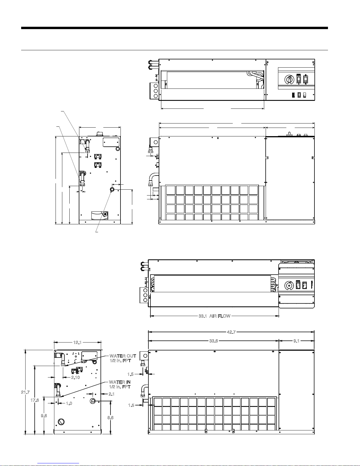
Water Piping
The proper water flow must be provided to each unit whenever the
unit operates. To assure proper flow, use pressure/temperature
ports to determine the flow rate. These ports should be located at
the supply and return water connections on the unit. The proper
flow rate cannot be accurately set without measuring the water
pressure drop through the refrigerant-to-water heat exchanger.
All source water connections on commercial units are fittings that
accept a male pipe thread (MPT). Insert the connectors by hand,
then tighten the fitting with a wrench to provide a leakproof joint.
When connecting to an open loop (groundwater) system, thread
any copper MPT fitting into the connector and tighten in the same
manner as described above.
Refrigerant Systems
To maintain sealed circuit integrity, do not install service gauges
unless unit operation appears abnormal. Compare the change in
temperature on the air side as well as the water side to the Unit
Operating Parameters tables. If the unit’s performance is not
within the ranges listed, and the airflow and water flow are known
to be correct, gauges should then be installed and superheat and
subcooling numbers calculated. If superheat and subcooling are
outside recommended ranges, an adjustment to the refrigerant
charge may be necessary.
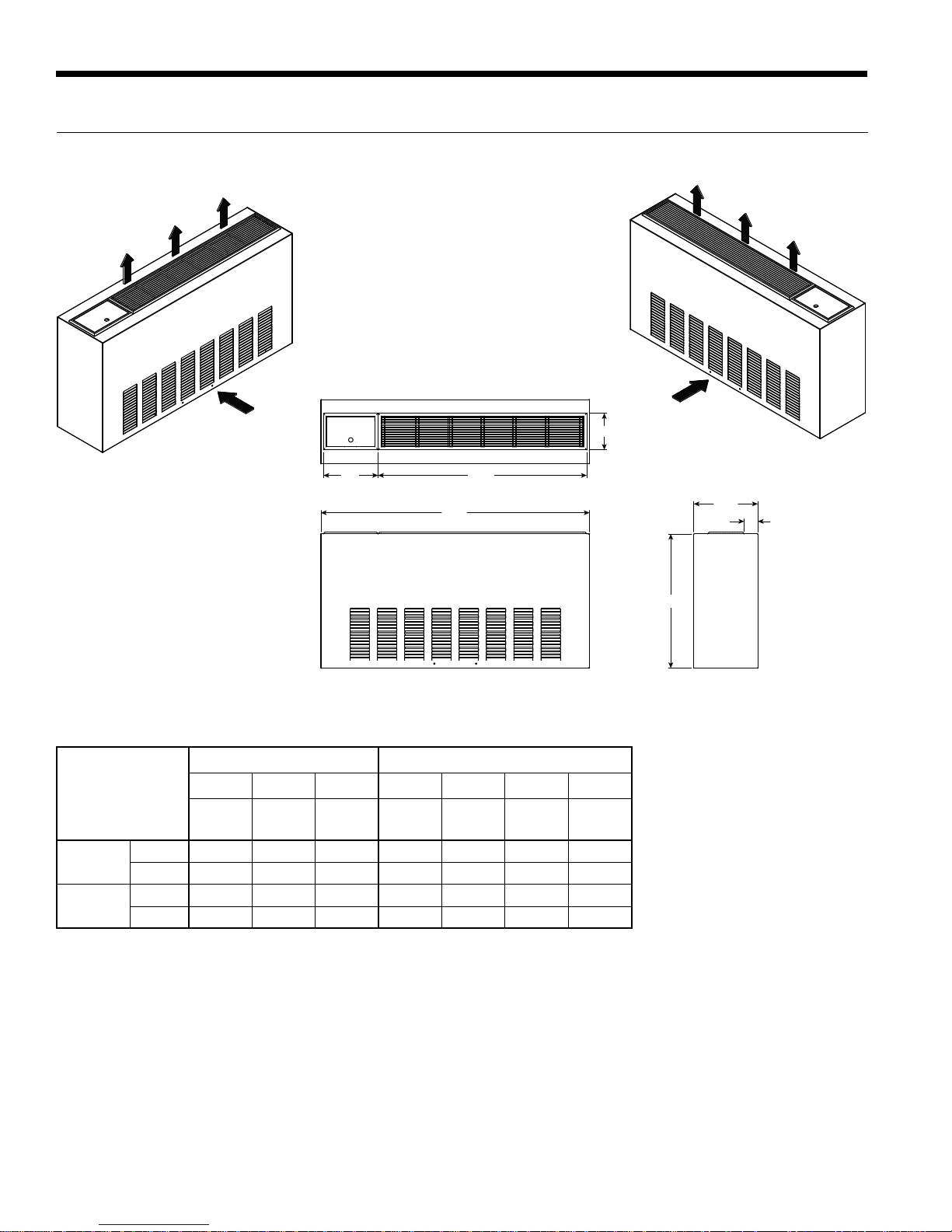
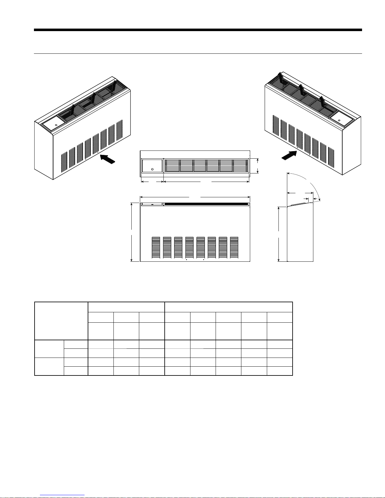
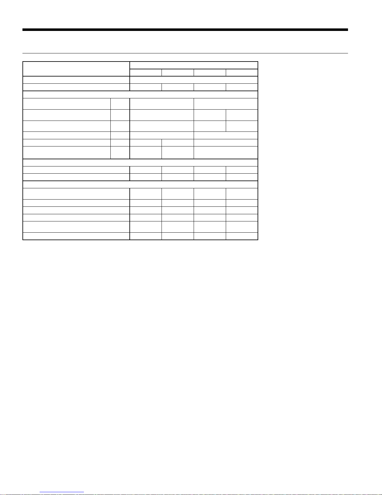
General Installation Information