Contractor: P.O.:
Engineer:
Project Name: Unit Tag:
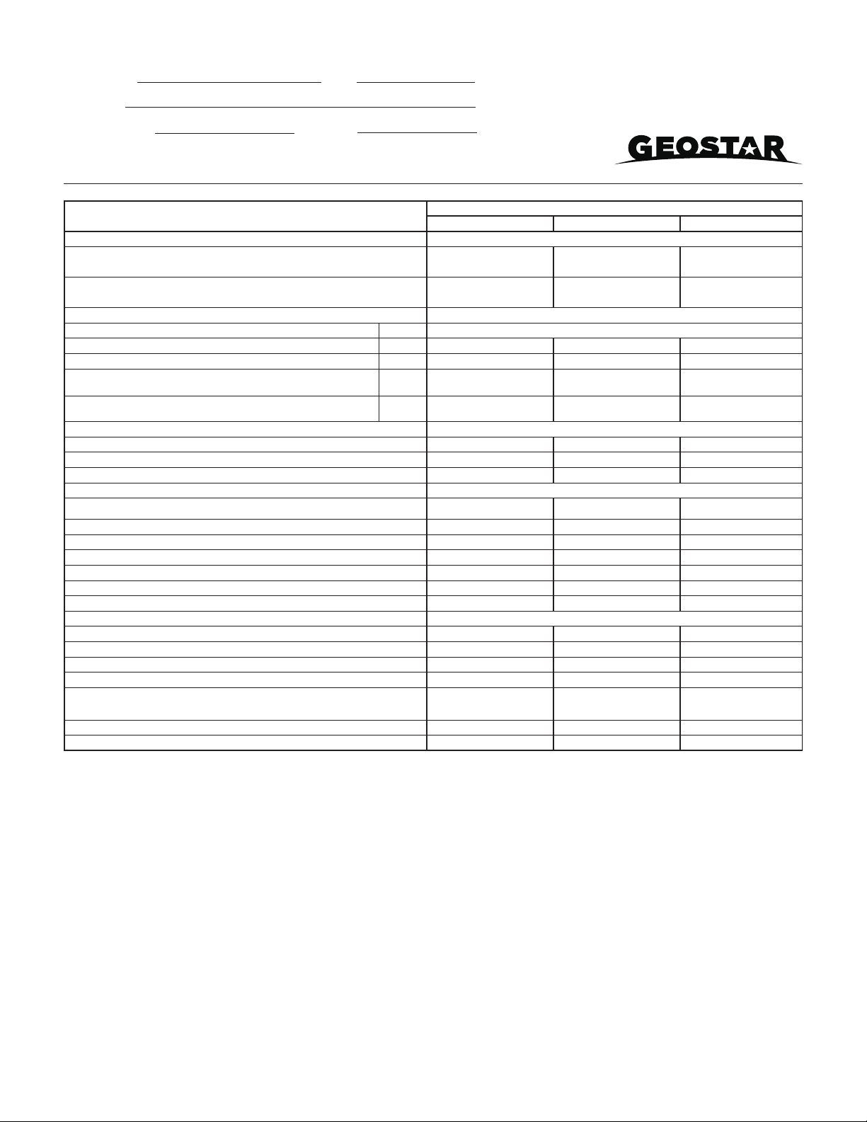
Blower Performance Data
ECM Speed Info
1
▶2◀G
3
4
5
6
7
8
9
10
11
12
Option ◀▶ Enter ◙
ECM Speed Info
1
2G
▶3◀Lo
4
5
6
7
8
9
10
11
12
Option ◀▶ Enter ◙
ECM Speed Info
1
2G
3Lo
4
5
▶6◀Hi
7
8
9
10
11
12
Option ◀▶ Enter ◙
ECM Speed Info
1
2G
3Lo
4
5
6Hi
7
8
9
▶10 ◀Aux
11
12
Option ◀▶ Enter ◙
ECM Speed Info
Blower Only Speed 3
Lo Compressor 6
Hi Compressor 9
Aux Heat 10
Want To Change?
Yes
Option ◀▶
No
Enter ◙
Cooling Airflow Setup
--- ECM Only ---
The airflow will be
adjusted by the chosen
amount in cooling mode.
Adjustment:
-15%
Want To Change?
Yes
Option ◀▶
No
Enter ◙
Cooling Airflow Setup
--- ECM Only ---
The airflow will be
adjusted by the chosen
amount in cooling mode.
Adjustment:
-15%
Change ▼▲ Enter ◙
Setting Blower Speed - Variable Speed ECM
The ABC board’s Yellow Config LED will flash the current ECM
blower speed selections for G, low, and high continuously with a
short pause in between. The speeds can also be confirmed with the
ID Tool under the Setup/ECM Setup screen. The Aux will not be
flashed but can be viewed in the AID Tool. The ECM blower motor
speeds can be field adjusted with or without using an AID Tool.
ariable Speed ECM Setup without an AID Tool
The blower speeds for G only, Low (Y1), and High (Y2/Aux) can be
adjusted directly at the Aurora ABC board which utilizes the push
button (SW1) on the ABC board. This procedure is outlined in the
ECM Configuration Mode portion of the Aurora ‘Base’ Control System
section. The Aux cannot be set manually without an AID Tool.
ariable Speed ECM Setup with an AID Tool
much easier method utilizes the AID Tool to change the airflow
using the procedure below. First navigate to the Setup screen and
then select ECM Setup. This screen displays the current ECM
settings. It allows the technician to enter the setup screens to
change the ECM settings. Change the highlighted item using the
◀and ▶buttons and then press the ◙button to select the item.
Selecting YES will enter ECM speed
setup, while selecting NO will return to
the previous screen.
ECM Speed Setup - These screens allow the technician to select
the G, low, high, and auxiliary heat blower speed for the ECM
blower motor. Change the highlighted item using the ▲and ▼
buttons. Press the ◙button to select the speed.
After the auxiliary heat speed setting is selected the AID Tool will
automatically transfer back to the ECM Setup screen.
Cooling Airflow Setup - These screens allow the technician to select
-15%, -10%, -5%, None or +5% change from the heating airflow.
Change the adjustment percentage using the ▲and ▼buttons.
Press the ◙button to save the change.
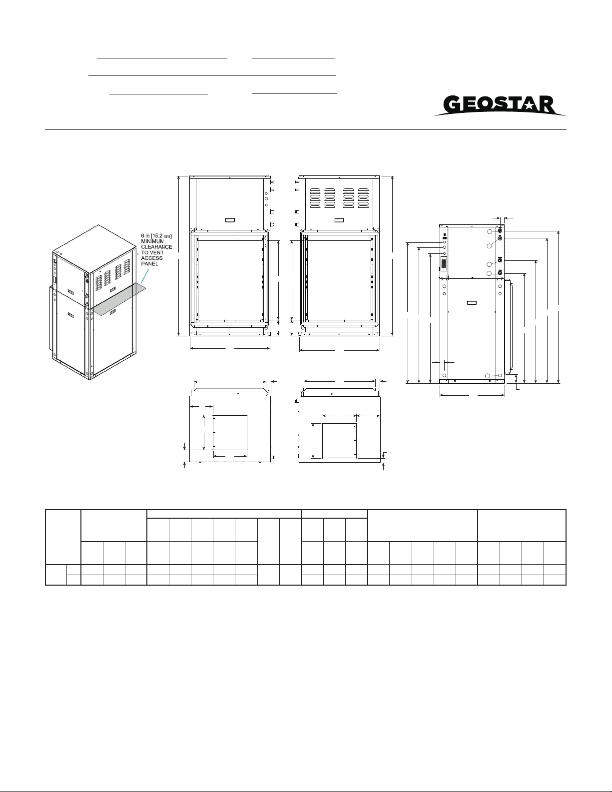
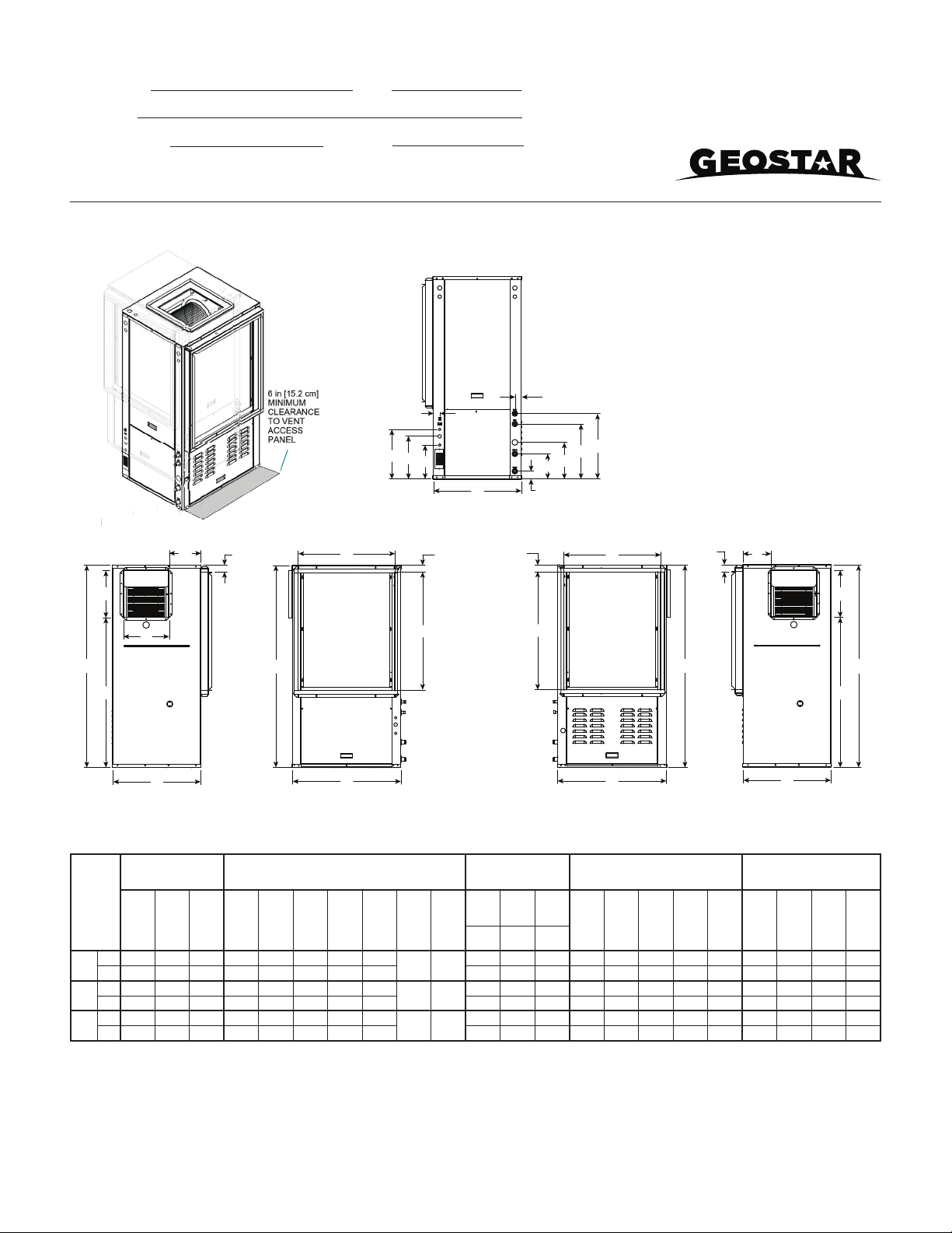
Variable Speed ECM Blower Motor
Model
Air Flow
Max
ESP
Speed
1
Speed
2
Speed
3
Speed
4
Speed
5
Speed
6
Speed
7
Speed
8
Speed
9
Speed
10
Speed
11
Speed
12
036 0.50 285 380
G
525
L
675 815 980 1100 1220 1330 1440
H
1540
Aux
1575
036 w/1hp* 0.75 480 565
G
665
L
761 870 1000 1100 1200 1300 1410
H
1520
Aux
1630
048 0.75 475 620
G
730
L
850 1020 1140 1270 1400 1520 1650
H
1790
Aux
1925
060 0.75 400 600
G
830
L
1050 1230 1400 1560 1700 1870 2010
H
2140
Aux
2265
**VS Compressor Speed 1-2 3-4 5-6 7-8 9-10 11-12
** VS Compressor speed is given for the factory default cfm settings. When the cfm default settings are changed it will change the relationship to the
compressor speed that is shown in the table. In cooling mode compressor speeds 10-12 are only available when SuperBoost mode is selected at the
thermostat.
* Optional 1 hp Variable Speed ECM
Factory settings are at recommended L , H and Aux positions
“G” may be located anywhere within the airflow table
“L” setting should be located within the boldface cfm range
“H” setting MUST be located within the shaded cfm range
“Aux” setting MUST be equal to or greater than “H” setting
“Aux” setting MUST be equal to or greater than the minimum allowable cfm for the auxiliary heater kit (see auxiliary heat ratings table)
Cfm is controlled within 5% up to the maximum ESP
Max ESP includes allowance for wet coil and standard filter
6/7/12
SD2700AGA 02/21 10 Page _____ of _____
Sycamore Series
3 - 5 Tons 60Hz
The manufacturer works continually to improve its products. As a result, the design and specifications of each product at the time of order may be changed without notice. Purchaser’s approval of this data set signifies that the equipment is acceptable under the provisions
of the job specification. Statements and other information contained herein are not express warranties and do not form the basis of any bargain between the parties, but are merely the manufacturer’s opinion or commendation of its products.