Geotech TempHion ISE User manual

Precision Environmental Sensors
An ON
I
CON Brand
PROUDLY
MADE
IN THE
USA
C
e
r
t
i
f
i
e
d
C
o
m
p
a
n
y
ISO
9001:2008
TempHion
pH/ORP (Redox) / ISE Smart Sensor
and Data Logger Instructions
TempHion pH/
ORP (Redox)
TempHion ISE
For Sales & Service Contact
2650 E. 40th Ave. • Denver, CO 80205
Phone 303-320-4764 • Fax 303-322-7242
1-800-833-7958
www.geotechenv.com

TEMPHION INSTRUCTIONS
Seametrics • 253.872.0284 Page 2 seametrics.com

TEMPHION INSTRUCTIONS
Seametrics • 253.872.0284 Page 3 seametrics.com
General Information
General Information ...................................................................................................................................................Page 4
Dimensions ....................................................................................................................................................................Page 4
Specications ................................................................................................................................................................Page 5
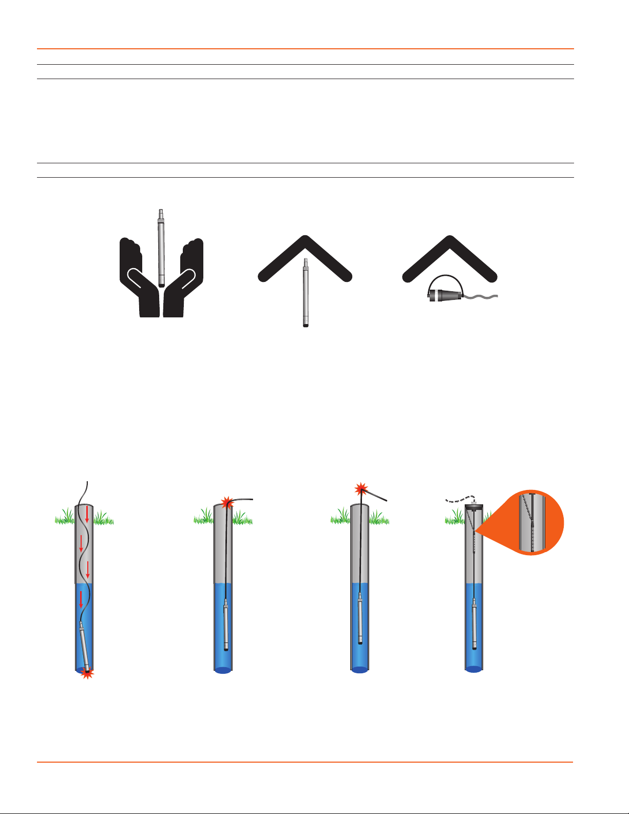
Initial Inspection and Handling..............................................................................................................................Page 6
Do’s and Don’ts............................................................................................................................................................Page 6
TempHion Reference Electrode..............................................................................................................................Page 7
General Precautions....................................................................................................................................................Page 7
Installation
Connecting External Power......................................................................................................................................Page 8
Connecting a TempHion to a Computer ............................................................................................................Page 8
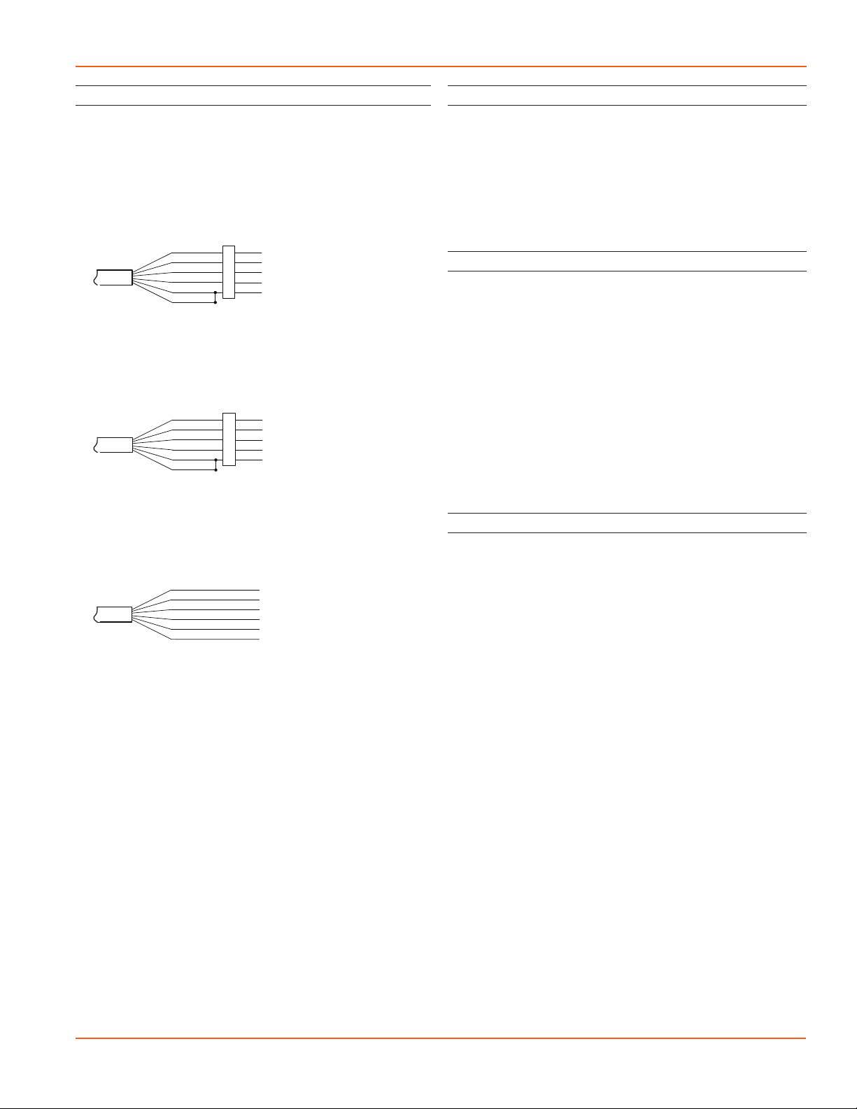
Cable Wiring..................................................................................................................................................................Page 9
Installing Aqua4Plus or Aqua4Plus Lite Software ...........................................................................................Page 9
Using Without Aqua4Plus or Aqua4Plus Lite Software ................................................................................Page 9
Grounding Issues.........................................................................................................................................................Page 9
Installing the Sensor...................................................................................................................................................Page 10
Settings and Calibration
General Calibration Information............................................................................................................................Page 11
Important Calibration Notes ...................................................................................................................................Page 11
pH Channel ....................................................................................................................................................................Page 12
Pressure Channel .........................................................................................................................................................Page 12
ISE Channel ....................................................................................................................................................................Page 13
ORP (Redox) .................................................................................................................................................................Page 15
Operation
Collecting Data with Aqua4Plus and Aqua4Plus Lite ....................................................................................Page 16
Real Time Monitor.......................................................................................................................................................Page 16
Setting up Data Recording ......................................................................................................................................Page 16
Retrieving Data.............................................................................................................................................................Page 16
Viewing Data .................................................................................................................................................................Page 16
Exporting Data..............................................................................................................................................................Page 17
A Word about Units....................................................................................................................................................Page 17
Direct Read Modbus/SDI-12
Setting Units for Direct Read ..................................................................................................................................Page 17
Power Consideration ..................................................................................................................................................Page 18
Reading via Modbus RTU .........................................................................................................................................Page 18
Reading via SDI-12......................................................................................................................................................Page 19
Maintenance and Reference
Sensor/Cable/End Connections .............................................................................................................................Page 21
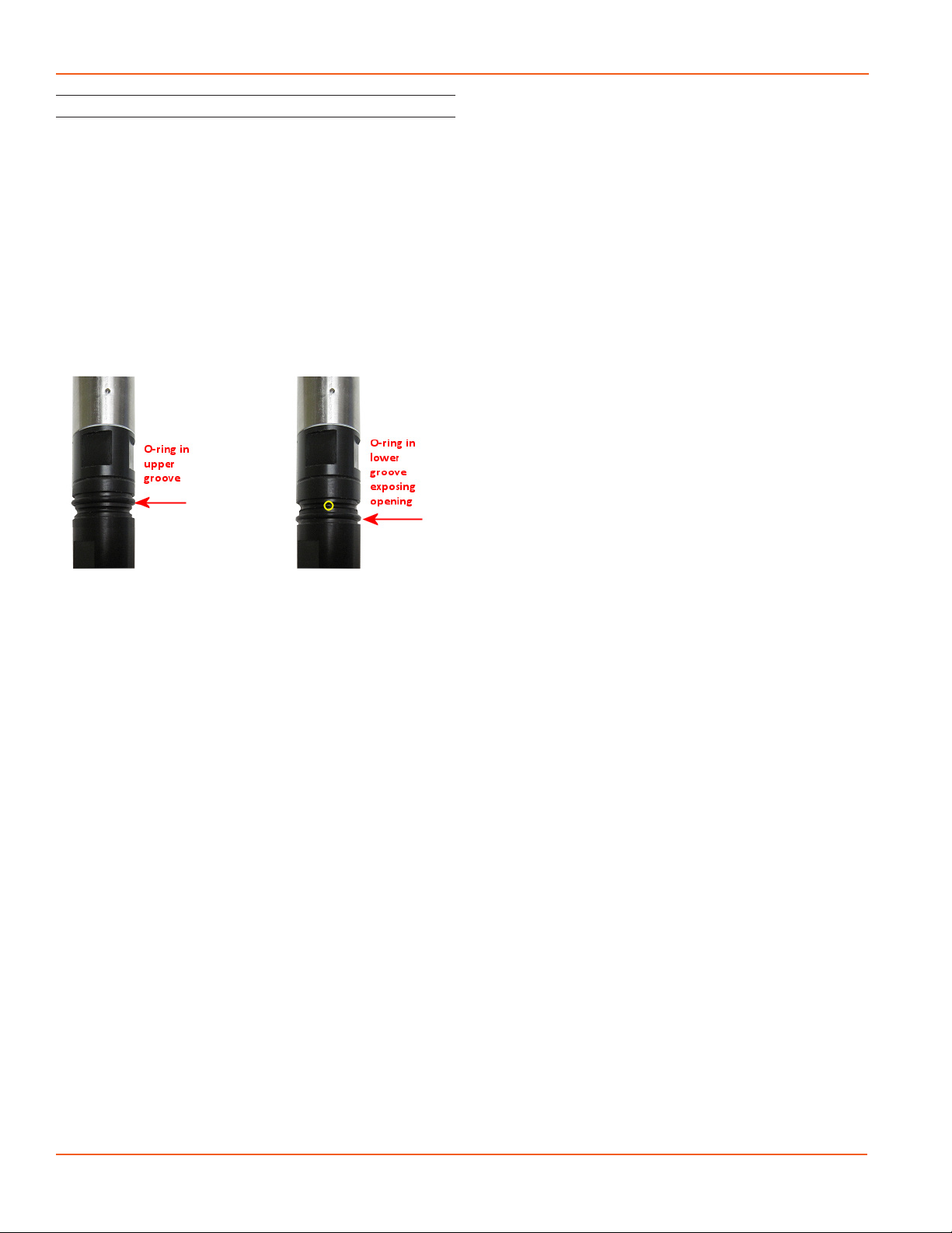
Care and Filling of Reference Solution................................................................................................................Page 21
pH Field Calibration Temperature Chart.............................................................................................................Page 22
M & I Range for pH Calibration.............................................................................................................................Page 22
How to Store and Recondition...............................................................................................................................Page 22
Changing Batteries......................................................................................................................................................Page 23
Troubleshooting
Problems/Probable Causes/Things to Try..........................................................................................................Page 26
TABLE OF CONTENTS
IF USING ALKALINE BATTERIES—PREVENT BATTERY LEAKAGE!
TempHion sensors are typically shipped with lithium batteries. If, however,
you are using alkaline batteries, be aware that under some circumstances
alkaline batteries can leak, causing damage to the sensor. To prevent leakage,
the following is recommended. (Does not apply to lithium batteries.)
• Change the batteries at least every 18 months.
• If the sensor will not be deployed for 3 months or more, remove the
batteries.

TEMPHION INSTRUCTIONS
Seametrics • 253.872.0284 Page 4 seametrics.com
GENERAL INFORMATION
The Seametrics TempHion™ Smart Sensor is a
microprocessor-based submersible sensor with built-in
data logging, storing thousands of records in non-volatile
memory. The pH/ORP version measures pH, ORP (Redox),
and temperature. The ISE version measures bromide and
temperature.
The internal processor in the TempHion allows for easy
calibration, using the calibration utilities in Aqua4Plus/
Aqua4Plus Lite. Once calibrated, this calibration data is
stored in non-volatile memory within the Smart Sensor.
When data is collected, this calibration information is
applied to the data, resulting in highly accurate readings at
a wide range of temperatures.
The TempHion is powered internally with two AA batteries.
Alternately it can be powered with an external auxiliary
power supply for data intensive applications. The unit is
programmed using Seametrics’ easy-to-use Aqua4Plus
or Aqua4Plus Lite control software. Once programmed
the unit will measure and collect data on a variety of time
intervals.
Several TempHions, or a combination of TempHions
and other Seametrics Smart Sensors, can be networked
together and controlled from one location directly from a
single computer.
While most will use the TempHion with our free, easy-
to-use Aqua4Plus Lite or Aqua4Plus software, it is by no
means limited to that software. You can use your own
Modbus®RTU or SDI-12 software or logging equipment to
read measurements, thus tying into your existing systems
and data bases.
Dimensions
17.96” (45.6 cm)
17.96” (45.6 cm) Diameter
0.75” (1.9 cm)
0.28” (0.7 cm)
0.28” (0.7 cm)
Cableless
0.25” (0.6 cm)
Shorter
pH/ORP Version
ISE Version
pH/ORP element
ISE element
Reference Reservoir
Non-batttery versions are 3.8” (9.65 cm) shorter.

TEMPHION INSTRUCTIONS
Seametrics • 253.872.0284 Page 5 seametrics.com
Specications*
GENERAL INFORMATION
Housing & Cable Weight 0.8 lb. (0.4 kg)
Body Material Acetal & 316 stainless or titanium
Wire Seal
Material
Fluoropolymer and PTFE
Cable Submersible: polyurethane, polyethylene, or ETFE (4 lb./100 ft., 1.8 kg/30 m)
Field Connector Standard
Temperature Operating Range 0˚ to 55˚C (32˚ to 131˚F)
Storage Range Without batteries: –20˚ to 80˚C (–4˚ to 176˚F)
Power Internal Battery Two lithium ‘AA’ batteries - Expected battery life: 18 months at 15 min. polling interval (may vary do to
environmental factors)
Auxiliary 12 Vdc - Nominal, 6–16 Vdc - range
Communication Modbus® RS485 Modbus® RTU, output=32bit IEEE oating point
SDI-12 SDI-12 (ver. 1.3) - ASCII
Logging Memory 4MB - 200,000 records
Logging Types Variable, user-dened, proled
Logging Rates 2x/sec maximum, no minimum
Baud Rates 9600, 19200, 38400
Software Complimentary Aqua4Plus and Aqua4Plus Lite
Networking 32 available addresses per junction (Address range: 1 to 255)
File Formats .a4d and .csv (also .xls in Windows 8 and earlier)
Output Channels Temperature pH ORP Bromide
Element 30K ohm thermistor,
Epoxy bead/external
housing
Glass combination
electrode
Platinum ring Ag/AgCl solid-state
electrode (Ion electrode
method)
Accuracy ±0.2˚C ±0.2 pH units, 0.1% mV
value (typical)
0.1 mVH, 0.1% mV value
(typical)
±5.0% of measured value
(typical)
Resolution 0.1˚C 0.01 pH units 0.01 mVH units 0.1 ppm
Units Celsius, Fahrenheit,
Kelvin
pH, mV Eh, mV ppm, mV
Range 0˚ to 55˚C (32˚ to 131˚F) 0-14 pH units / -538 to
260 mV
± 1200 mV 0–10,000 ppm
Compensated --- 0˚ to 40˚C (32˚ to 104˚F) 0˚ to 40˚C (32˚ to 104˚F) Isopotential point
characterization
Calibration --- One or two point
calibration w/ pH buers
(4 & 7 or 7 & 10)
EH 1 pt. calibration One or two point
calibration w/ ionic
strength adjustment
Reference
Solution
Potassium Nitrate -
(KNO3)
Potassium Nitrate -
(KNO3)
Potassium Nitrate -
(KNO3)
Reference Ag/AgCl solid state electrode, capillary liquid junction, TempHion™ reference solution
Maximum Depth pH/ORP: 700 ft (210 m) / 300 psi, ISE: 230 ft (70 m)/100 psi
Environmental IP68, NEMA 6P
*Specications subject to change. Please consult out web site for the most current data (seametrics.com). Modbus is a registered trademark of Schneider Electric.

TEMPHION INSTRUCTIONS
Seametrics • 253.872.0284 Page 6 seametrics.com
GENERAL INFORMATION
Initial Inspection and Handling
Upon receipt of your smart sensor, inspect the shipping package for damage. If any damage is apparent, note the signs
of damage on the appropriate shipping form. After opening the carton, look for concealed damage, such as a cut cable.
If concealed damage is found, immediately le a claim with the carrier.
Check the label attached to the cable at the connector end for the proper cable length.
Do’s and Don’ts
Don’t drop into well
Lower gently to prevent
damage
Don’t scrape cable
over edge of well
May nick or fray the
cable
Don’t bend cable sharply
May weaken internal wires
Don’t support sensor
with the connector
Use a strain relief device
Do handle sensor with
care
Do store sensor in
a dry, inside area
when not in use. (See
also “How to Store” in
Maintenance section)
Do install sensor so the
connector end is kept
dry

TEMPHION INSTRUCTIONS
Seametrics • 253.872.0284 Page 7 seametrics.com
GENERAL INFORMATION
TempHion™ Reference Electrode
TempHion’s patented reference electrode is the key to
TempHion’s superior downhole/high pressure performance.
TempHion uses a long capillary pathway, initially lled
with reference electrode lling solution, to separate the
reference electrode chamber from the solution being
analyzed. In addition, TempHion’s reference electrode is
lled without any air (which is compressible). With this
construction, the principle mechanism that will eventually
allow test solution to enter the reference chamber and
contaminate the reference electrode lling solution is
diusion – an exceedingly slow mechanism. Further, while
the capillary pathway is narrow by garden hose standards,
its open cross-section is huge compared to the microscopic
openings in a conventional porous ceramic uid/uid
junction. It is therefore much less susceptible to fouling.
TempHion’s proven stability under actual eld conditions is
measured in weeks or months, rather than hours or days!
The gure below illustrates the construction of the
TempHion reference electrode. Please note that the
capillary pathway between the reference and test solutions
is established using a modied screw thread. This means
that the capillary can be easily opened up for cleaning,
relling, or other maintenance.
Reference Electrode Assembly: The modied thread provides
a continuous liquid path between the solution in which the
instrument is immersed and the reference element.
TempHions with standard pH elements, ISE elements,
and ORP elements come with the TempHion Reference
Electrode, as described above.
Reference
Electrode
Assembly
Liquid Junction Port
Outer Reference
Housing
Capillary Flow path
(Modied Thread)
Reference Electrode
Filling Solution
Reservoir
Reference Element
General Precautions
The rest of this manual includes step-by-step instructions
for setting up the TempHion calibrating it, and using it in
the eld. When reading and following the instructions in
these sections, keep these very important considerations
in mind:
• Do not handle the surfaces of the sensing
electrodes. Oils from ngers can “blind” the
reactive surface. Rough handling can scratch the
reactive surface.
• Use calibration standards that are accurately
prepared. Discard standards after use. Do not
return the used standards to the bottles of “fresh”
solution.
• When TempHion’s reference electrode contains
lling solution, the O-ring at the top of the
reference assembly must be in the upper position.
(See further details under Installation later in this
manual.)
• For any step-change in temperature (e.g., where
calibration standards are at a dierent temperature
than water to be tested) allow the instrument to
come to complete thermal equilibrium before
making measurements. Up to 30 minutes may be
required.

TEMPHION INSTRUCTIONS
Seametrics • 253.872.0284 Page 8 seametrics.com
Connecting sensor to your computer using
an RS485/RS232 adapter and an interface cable.
Connecting with a USB/Serial Adapter
USB-to-Serial cables are readily available from many
electronics and computer stores, as well as numerous sites
on the Internet. Seametrics has tested and recommends
the Keyspan USA-19HS. Install as follows:
• Plug into USB port.
• Install the drivers provided with the particular unit.
• Determine the port number to which the adapter is
assigned.
• Right-click on My Computer.
• From the popup menu, select Manage to open
the Computer Management window.
• On left panel, click on Device Manager.
• On right panel, double-click on Ports.
• A list of active COM ports will be displayed. Note
the COM number assigned to the adapter you
just installed.
For example:
• Close Manager.
• Connect to the sensor.
• On the Aqua4Plus software, select the COM port
noted above. (If you do not see your new COM port
in the dropdown box, open the Communications
dialog box from the Options menu. Increase the
Highest COM port number, up to a maximum of
15.)
Connecting sensor to your computer using
a USB to Serial adapter and an interface cable.
PC or Laptop
Computer
RS485/RS232
Adapter
Interface Cable
Serial Port
Sensor
Screw-
Sensor
cap
Cableless
Conguration
Interface
Cable
PC or Laptop
Computer
USB PortUSB-to-Serial
Adapter
RS232/RS485
Adapter
Sensor
Screw-
Sensor
cap
Cableless
Conguration
INSTALLATION
Connecting External Power
The TempHion comes with two 1.5V AA internal batteries.
If auxiliary power is desired, you can use a 6–16 VDC supply
that can provide 15 mA. Connect to Vaux++ (pin 1 - white)
and Ground (pin 5 - blue) or contact Seametrics for auxiliary
power supplies.
Connecting the TempHion to a Computer
Cabled sensors are terminated with a weather-resistant
connector. Cableless sensors are terminated with a weather-
resistant connector that is inside a screw-cap. Connect the
weather-resistant connector to your computer’s USB port
as shown below.
Connecting sensor to your computer using
Seametrics’ USB to RS485 adapter.
Aqua4Plus and Aqua4Plus Lite communicate with the
sensor using the USB to RS485 adapter cable. This cable
requires drivers to be installed on your computer. If you
are connected to the Internet when you rst plug in the
cable, it will normally obtain and install the correct drivers
automatically. If this does not happen, or if you do not have
Internet connection, you can use Aqua4Plus or Aqua4Plus
Lite to install the drivers. In Aqua4Plus, select Install USB/
RS485 Drivers from the Utilities menu; in Aqua4Plus Lite,
select the same from the Program Conguration menu.
Select your operating system, and then click Install.
Alternate Connection Options
Seametrics recommends connecting the sensor to your
computer using the Seametrics USB cable. However, when
using Aqua4Plus, the sensor can also be connected using
an RS232 serial port or a USB-to-Serial cable, as described
below. (Note: Aqua4Plus Lite can only communicate using
the Seametrics USB cable.)
Connecting via RS232 Serial Port
Connect the weather-resistant connector to your
computer’s serial port as shown below.
PC or Laptop
Computer
USB Port
USB to RS485
Adapter
Sensor
Cableless
Conguration
Screw-
Sensor
cap

TEMPHION INSTRUCTIONS
Seametrics • 253.872.0284 Page 9 seametrics.com
INSTALLATION
Cable Wiring
If you buy your cabled sensor with a connector installed
(the normal conguration), no further wiring is needed.
For reference purposes, the rst two diagrams below show
the pinout from the connector for various scenarios. The
nal diagram shows the pinout if you bought your sensor
without a connector for use with SDI-12.
For Modbus®—with 5-pin connector
For SDI-12—with 5-pin connector
For SDI-12—without connector
White
Purple
Yellow
Brown
Blue
Shield
12 VDC+ (Vaux)
Modbus D- (Not used)
Modbus D+ (Not used)
SDI-12 Signal
12 VDC- (GND)
Earth ground
White
Purple
Yellow
Brown
Blue
Shield
12 VDC+ (Vaux)
Modbus D- (Not used)
Modbus D+ (Not used)
SDI-12 Signal
12 VDC- (GND)
1
2
3
4
5
5-Pin
Connector
White
Purple
Yellow
Brown
Blue
Shield
12 VDC+ (Vaux)
Modbus D-
Modbus D+
SDI-12 (Not used)
12 VDC- (GND)
1
2
3
4
5
5-Pin
Connector
Installing Aqua4Plus or Aqua4Plus Lite Software
The TempHion comes with the Aqua4Plus or Aqua4Plus
Lite host software that is installed on your PC or laptop. Use
this software to program the datalogger, to retrieve data
from the logger, to view collected data, and to export data
to external les for use with spreadsheets or databases.
Refer to the software manuals for details on installing and
using Aqua4Plus or Aqua4Plus Lite.
Using TempHion Without Aqua4Plus or Aqua4Plus Lite
Most users will use the TempHion with Seametrics’
Aqua4Plus or Aqua4Plus Lite software. However, the
TempHion is quite versatile, communicating via either
Modbus®or SDI-12 interfaces, allowing you to do the
following:
• Read a TempHion via Modbus®using your own
software.
• Read a TempHion via SDI-12 protocol.
• Display readings from a TempHion on a panel
meter.
If you want to use one of these methods, see the chapter
Direct Read Modbus®/SDI-12.
Grounding Issues
It is commonly known that when using electronic
equipment, both personnel and equipment need to be
protected from high power spikes that may be caused by
lightning, power line surges, or faulty equipment. Without
a proper grounding system, a power spike will nd the path
of least resistance to earth ground—whether that path is
through sensitive electronic equipment or the person
operating the equipment. In order to ensure safety and
prevent equipment damage, a grounding system must be
used to provide a low resistance path to ground.
When using several pieces of interconnected equipment,
each of which may have its own ground, problems with
noise, signal interference, and erroneous readings may be
noted. This is caused by a condition known as a Ground
Loop. Because of natural resistance in the earth between
the grounding points, current can ow between the points,
creating an unexpected voltage dierence and resulting
erroneous readings.
The single most important step in minimizing a ground loop
is to tie all equipment (sensors, dataloggers, external power
sources, and any other associated equipment) to a single
common grounding point. Seametrics recommends
connecting the shield to ground at the connector end.

TEMPHION INSTRUCTIONS
Seametrics • 253.872.0284 Page 10 seametrics.com
INSTALLATION
Installing the Sensor
The black reference reservoir at the lower end of the
TempHion Smart Sensor is shipped lled with Seametrics
reference solution. (If your reference reservoir is not lled,
see the Maintenance section in this manual.) The black
reference assembly has two grooves. The upper groove
contains a small hole that forms the liquid junction port.
During shipping and storage, an o-ring is located in the
upper groove, preventing reference solution leakage and
contamination. Be sure to move the o-ring to the lower
groove before deploying, thus exposing the liquid junction
port. If the o-ring continues to cover the opening, readings
will not be representative or accurate.
Be sure to move the o-ring to the lower groove before
deploying, thus exposing the liquid junction port.
Lower the sensor to the desired depth. Fasten the cable
to the well head using tie wraps or a weather proof strain-
relief system. (Note that for shallow installations the liquid
in which the sensor is submerged must, at all times, reach
high enough to cover the sensing element cutout.)
Be sure the supplied cap is securely placed on the weather-
resistant connector at the top of the cable. Do not install
such that the connector might become submerged with
changing weather conditions. The connector can withstand
incidental splashing but is not designed to be submerged.
Note about Calibration
The TempHion must be calibrated before deploying.
The TempHion has one temperature channel and four
millivolt channels. The millivolt channels can be congured
to measure pH, ORP (Redox), or various selected
ions. Before leaving the factory, your sensor has been
congured specically for you. All unneeded channels
have been disabled, and the active channels have been
pre-congured. Disabled channels will not display in
Aqua4Plus/Aqua4Plus Lite. (Note: Some older TempHions
may have more channels. If yours has more channels, refer
to the documentation that came with the unit or contact
Seametrics for more information.)
All active channels can be calibrated in the eld.
Temperature channels rarely need calibrating, however the
pH, ORP (Redox), and ISE channels should be calibrated
before rst use and periodically thereafter.
See the next section, “Settings and Calibration” for detailed
calibration instructions.

TEMPHION INSTRUCTIONS
Seametrics • 253.872.0284 Page 11 seametrics.com
General Calibration Information
The TempHion should be calibrated before rst use and
periodically thereafter. It should also be calibrated if moving
to a dierent sampling environment where readings will be
signicantly dierent than the current environment.
Environmental conditions of turbulence and temperature
swings, as well as local likelihood for bio-fouling or
mineral deposition, can vary considerably from site to site.
Therefore, where the sensor is to be used for long-term
monitoring, it is recommended that the calibration be
initially checked frequently until a performance history is
established.
Aqua4Plus/Aqua4Plus Lite provides an easy-to-use
calibration calculator for performing one- or two-point in-
eld calibrations. Two-point calibrations are more accurate
and should be used whenever possible. A Calibration Kit
is available from Seametrics, which includes a beaker,
pipette, measuring beaker, and stand.
Field calibration is performed on each channel separately.
To calibrate a specic channel, select Settings and
Conguration from the Congure Menu in Aqua4Plus
(click the Settings button in Aqua4Plus Lite), and then
click on the channel to be calibrated.
Step-by-step instructions will be displayed on the right
side of the window.
Note that the temperature channel rarely needs adjustment.
If you think your temperature channel needs calibrating,
contact your service representative.
Use the calibration calculator to perform one- and two-
point calibrations.
SETTINGS AND CALIBRATION
IMPORTANT CALIBRATION NOTES!
Data Files
• Calibration can only be done when
there is no data stored on the sensor.
Retrieve any data you want and then
erase the data before continuing.
Filling Solution Reservoir
• In order for the TempHion Smart
Sensor to calibrate and function
correctly, the lling solution reservoir
must be properly lled with reference
solution. For details, see Maintenance
section.
• Be sure the o-ring on the black
reference housing has been moved to
the lower groove, exposing the liquid
junction port.
Calibration Buers and Solutions
• Refer to the following sections for
specic solutions and buers.
• Important! The sensor and all
calibration buers and solutions
should be at the same temperature
before and during calibration.
Reconditioning
• If your reference electrode has been
stored dry or in KCl solution, you
should let it sit at least a half hour
after lling with reference solution
before using or calibrating.
• If your pH sensor has been stored
with the bulb dry, you should soak it
in your rst pH buer for about four
hours to recondition the bulb before
calibrating.
• If your ISE sensor has been stored with
the element dry, you should soak it
in your rst calibration solution for
at least a half hour before using or
calibrating.

TEMPHION INSTRUCTIONS
Seametrics • 253.872.0284 Page 12 seametrics.com
SETTINGS AND CALIBRATION
Preparation
• Seametrics recommends pH buers of 4, 7, and 10 for
calibration. For a one-point calibration, select the buer
closest to the expected values in your samples. For a two-
point calibration, select the two buers that most closely
bracket the expected values in your samples.
• Before calibrating, check the M & I Range Chart in the
Maintenance and Reference section for the range of M
and I values you can expect to obtain during calibration.
One-Point Calibration
— Compute Calibration Value —
• Prepare the buer.
• Rinse sensor rst with distilled water and then with small
amount of the buer.
• Place sensor in buer. (Buer must be deep enough to
cover the sensing bulb in the cutout on the sensor.)
• Allow time for sensor to stabilize.
• In the Ref pH box for the rst point, enter the
temperature adjusted reference pH as noted in the
preparation section above.
• Click rst Measure button.
• When readings have stabilized to your satisfaction, click
the OK button in the pop-up box.
— Applying Calibration Value —
• Observe the I value in the right hand section of the
calculator. This should be between the I values shown in
the M & I Range Chart.
• Click the Apply button to apply calibration values.
• The reference value, the computed I, and the sample
temperature will be transferred to the calibration elds.
• Click OK to save the values to the sensor.
— Verifying Settings —
• Using the Real Time Monitor, take a few readings while
the sensor is still in the buer. Be sure units are set to pH.
Readings should be very close to your selected buer.
IMPORTANT!
The pH of any buer varies slightly with
temperature change. For this reason, it is
important that you determine the current pH
value of the buer you are using. Refer to the
pH Field Calibration Temperature Chart in the
Maintenance and Reference section. From this
chart, determine the pH value at your current
buer temperature and use this value as the
“Ref pH” value in the calibration instructions
below. For example, if you are using a pH buer
of 7 and your buer temperature is 20˚C, then
you would enter 7.02 in the Ref pH box.
Two-Point Calibration
— Compute First Calibration Point —
• Prepare rst buer.
• Rinse sensor rst with distilled water and then with small
amount of rst buer.
• Place sensor in buer. (Buer must be deep enough to
cover the sensing bulb in the cutout on the sensor.)
• Allow time for sensor to stabilize.
• In the Ref pH box for the rst point, enter the temperature
adjusted reference pH as noted in the preparation section
above.
• Click rst Measure button.
• When readings have stabilized to your satisfaction, click
the OK button in the pop-up box.
— Compute Second Calibration Point —
• Prepare the second buer.
• Rinse sensor rst with distilled water and then with small
amount of second
• buer.
• Place sensor in second buer. (Buer must be deep
enough to cover the sensing bulb in the cutout on the
sensor.)
• In the Ref pH box for the second point, enter the
temperature adjusted reference pH as noted in the
preparation section above.
• Click second Measure button. (Note: measured
temperature must be +/- 1 degree of rst measured
temperature or calibration will not be accurate!)
• When readings have stabilized to your satisfaction, click
the OK button in the pop-up box.
— Applying Calibration Values —
• Observe the M and I values in the right hand section of
the calculator. These should be between the M and I
values shown in the M & I Range Chart.
• Click the Apply button to apply calibration values.
• The reference values, the computed M and I, and the
sample temperature will be transferred to the calibration
elds.
• Click OK to save the values to the sensor.
— Verifying Calibration Values—
• Using the Real Time Monitor, take a few readings while
the sensor is still in the buer. Be sure units are set to pH.
Readings should be very close to your selected buer.
pH Channel Calibration

TEMPHION INSTRUCTIONS
Seametrics • 253.872.0284 Page 13 seametrics.com
SETTINGS AND CALIBRATION
ISE Channel Calibration
Introduction to ISE Calibration
Seametrics recommends using the “known addition
method” for preparing calibration solutions. Using this
method, the sensor is placed in 100 mL of distilled or de-
ionized water. A small amount of standard is added to
create a known concentration. The rst point is measured.
An additional amount of the same standard is added to
create a second known concentration. The second point
is measured.
Seametrics recommends the calibration standards listed
below. The following instructions are based on using one
of these standards. If you use dierent standards or prefer
not to use the known addition method, you must use some
other method to determine the concentration used for the
rst and second point when calibrating.
Recommended Standards
Bromide
• 0.1 Molar NaBr (equates to 7990 ppm)
Preparation
• Select a standard that you will be using for calibration.
• Place 100 mL of distilled water in a beaker.
Note: Temperature of the water must remain the same
throughout the calibration. Temperature of the sensor
must also be this temperature prior to calibration.
One-Point Calibration
— Computing Calibration Value—
• Rinse sensor with distilled water and pat dry.
• Place sensor in beaker of distilled water, as prepared
above. (Solution must
be deep enough to cover the element cutout.)
• Add 1 cc of selected standard to the water. Depending
on which solution you are using, this will result in a
concentration as shown below:
• 0.1 Molar NaBr (Bromide) = 79.10 ppm
• Stir to distribute standard evenly.
• Allow time for sensor to stabilize (15–20 minutes).
• In the Ref ppm box for the rst point, enter the
concentration you have chosen.
• Click the rst Measure button. (Readings will be in mV).
• When readings have stabilized to your satisfaction, click
the OK button on the pop-up box.
— Applying Calibration Values—
• Observe the I value in the right hand section of the
calculator.
• Click the Apply button to apply calibration values.
• The reference value, the computed I, and the sample
temperature will be
transferred to the calibration elds.
• Click OK to save the values to the sensor.
— Verifying Calibration Values—
• Using the Real Time Monitor, take a few readings while
the sensor is still in the standard. Be sure units are set
to ppm. Readings should be very close to your selected
concentration.

TEMPHION INSTRUCTIONS
Seametrics • 253.872.0284 Page 14 seametrics.com
SETTINGS AND CALIBRATION
ISE Channel Calibration (continued)
Two-Point Calibration
— First Calibration Point—
• Rinse sensor with distilled water and pat dry.
• Place sensor in beaker of distilled water, as prepared
above. (Solution must be deep enough to cover the
element cutout.)
• Add 1 cc of selected standard to the water. Depending
on which solution you are using, this will result in a
concentration as shown below:
• 0.1 Molar NaBr (Bromide) = 79.10 ppm
• Stir to distribute standard evenly.
• Allow time for sensor to stabilize (15–20 minutes).
• In the Ref ppm box for the rst point, enter the
concentration you have chosen.
• Click the rst Measure button.
• When readings have stabilized to your satisfaction, click
the OK button on the pop-up box.
— Second Calibration Point—
• Add 10 cc of the same standard to the water.
Depending on which solution you are using, this will
result in a concentration as shown below:
• 0.1 Molar NaBr (Bromide) = 791.8 ppm
• Stir to distribute standard evenly.
• Allow time for sensor to stabilize (15–20 minutes).
• In the Ref ppm box for the second point, enter the
concentration you have chosen.
• Click the second Measure button.
• When readings have stabilized to your satisfaction,
click the OK button on the pop-up box.
— Applying Calibration Values—
• Observe the M and I values in the right hand section of
the calculator. M should be between –50 and –60.
• Click the Apply button to apply calibration values.
• The reference values, the computed M and I, and the
sample temperature will be transferred to the calibration
elds.
• Click OK to save the values to the sensor.
— Verifying Calibration Values—
• Using the Real Time Monitor, take a few readings while
the sensor is still in the standard. Be sure units are set
to ppm. Readings should be very close to your selected
concentration.

TEMPHION INSTRUCTIONS
Seametrics • 253.872.0284 Page 15 seametrics.com
SETTINGS AND CALIBRATION
ORP (Redox) Channel Calibration
Note on units: The unit “Eh” refers to readings in millivolts
referenced to a hydrogen electrode. In
other words, Eh represents millivolt
readings that would have been obtained
if using a hydrogen electrode. The units
“mV” are direct millivolt readings from the
sensor. From the program, set the display
units to either mV or Eh, whichever you will
be using on your alternate ORP (Redox)
meter.
— For Calibration You Will Need—
• A beaker or bucket of a sample that is representative of
what will be measured with the sensor. DO NOT USE
ZOBELL SOLUTION!
• An alternate ORP meter.
• Distilled or deionized water.
• Paper towels.
— Computing Calibration Value—
Note: When calibrating an ORP channel, do not use
the built-in calculator in the Settings and Calibration
Window. Instead, follow the instructions below.
• Rinse sensor with distilled or deionized water, and then
pat dry with clean paper towels.
• Place the sensor in sample. (Solution must be deep
enough to cover the element cutout.)
• Using the alternate meter, take a measurement of that
sample. Use either plain mV or Eh, whichever you
normally use.
• Open the Settings and Calibration window.
• Click on the ORP (Redox) channel, and then enter a zero
in the oset box.
• Click OK.
• Take two or three single readings using the Real Time
monitor and note the ORP value.
• Subtract this value from the value read by the alternate
meter.
— Applying Calibration —
• Re-open the Settings and Calibration window.
• Click on the ORP (Redox) channel, and then enter this
value in the oset box.
• Click OK to save the value to the sensor!!!
— Verifying Calibration —
• Take another couple single Real Time readings. These
should be close to the reading taken with the other
meter.

TEMPHION INSTRUCTIONS
Seametrics • 253.872.0284 Page 16 seametrics.com
OPERATION
Collecting Data with Aqua4Plus & Aqua4Plus Lite
Following is a brief overview on using Aqua4Plus/
Aqua4Plus Lite to collect data. Please refer to the software
instruction manuals for further details on conguring and
using Aqua4Plus/Aqua4Plus Lite.
Real Time Monitor
• Click Single to get a single reading.
• Click Start to get a reading once a second for 60
seconds.
• Click Stop to stop the reading.
Note: These are snapshot readings and are not recorded
on the sensor.
The Real Time Monitor gives a snapshot of the
current readings on the sensor.
Setting up Data Recording
Click the tool button. A Logging Schedule Window will
open. Refer to the software instruction manuals for details
in describing your schedule. Click the Start button to save
the schedule to the sensor and begin recording.
Using the Logging
Schedule Window,
describe the test
steps for your
particular test.
Retrieving Data from the Sensor/Datalogger
• Click on the le you want to retrieve.
• Click the tool button.
• Select a le location.
• Click Save.
• Click Start.
Select the
data le to
retrieve.
Viewing Data
• Click the or tool button to view data as
a table.
• Click the tool button to view data as a graph.
• Navigate to the desired le, then click the Open
button.
The File Display window displays your data in
a tabular format.

TEMPHION INSTRUCTIONS
Seametrics • 253.872.0284 Page 17 seametrics.com
OPERATION/DIRECT READ MODBUS & SDI-12
The Graph window displays your data on an
X Y coordinate graph.
Exporting Data to .csv or .xls Files*
• Click the or tool button to view data as
a table.
• Click on the tool button.
• Select a le location and enter a name for the le.
• Select a le type.
• Click Save.
* When using Windows 10, les can only be exported in .csv format. They
can then be opened manually from Excel or any other spreadsheet or
database program
A Word About Units
Readings from the TempHion Smart Sensor can be
displayed in various units. Select the units you want from
the Options | Display Units menu or from the Congure
Menu | Program Conguration | Set Computer Display
Units.
pH: pH or mV
ISE: ppm or mV
ORP (Redox): Eh or mV
Temperature: Degrees Celsius, Fahrenheit, Kelvin, or
ohms
When using pH, ppm, or Eh units, all readings are
automatically compensated for temperature and all eld
calibration factors are applied. When using millivolts or
ohms, only the actual millivolt or resistance values are
displayed, no adjustments are made.
DIRECT READ (MODBUS®OR SDI-12)
While the TempHion comes with Seametrics’ easy to use
Aqua4Plus or Aqua4Plus Lite software, you can also use
standard Modbus®RTU or SDI-12 equipment to easily
take readings, so as to tie into your existing equipment or
networks.
You may need to use Aqua4Plus/Aqua4Plus Lite to make
a few settings prior to directly reading the TempHion with
your equipment. These might include the units for the
returned values and/or the Modbus baud rate. These are
described in the following sections.
For Modbus direct read, you must have TempHion rmware
1.1 or higher. For SDI-12, you must have rmware 2.0 or
higher.
Setting Units for Direct Read
The TempHion has up to four data channels. The rst
channel is always temperature. The Temperature channel,
by default, uses degrees Celsius. If you want to change to
dierent units, for example, degrees Fahrenheit, set these
units using Aqua4Plus/Aqua4Plus Lite.
• From Aqua4Plus select Direct Read Units from the
Congure | Advanced menu.
• From Aqua4Plus Lite select Set Direct Read Units
from the Sensor Congure menu.
• On the popup box, click the down-arrows next to
Temperature, and then select the units you want.
• Click OK.
Select the units for your direct read
measurements, whether Modbus or SDI-12
The remaining channels are mV channels and can be
congured at the factory as pH, ORP (Redox), or ISE
channels. Each of the mV channels return two direct read
values. The rst is always mV. The second is either pH, ppm,
or Eh, depending on the channel type.
Once set, these units are saved on the sensor and direct
readings, either via Modbus or via SDI-12, will return values
using these units. (Note: These settings do not aect the
units used on the Aqua4Plus\Aqua4Plus Lite display. Refer
to the software manual for details.)

TEMPHION INSTRUCTIONS
Seametrics • 253.872.0284 Page 18 seametrics.com
DIRECT READ MODBUS & SDI-12
Power Consideration
If your sensor does not have internal batteries and is not
powered continuously by an auxiliary power supply, then
you must turn power on to the sensor at least two seconds
before a reading is to be taken to allow the sensor to warm
up.
Reading Via Modbus®RTU
Setting Baud Rate
Your TempHion comes congured to communicate at
38,400 baud, with 8 data bits, one stop bit, and no parity.
The sensor can also be set to 19,200 or 9600 baud, if
needed for your application. You must use Aqua4Plus, not
Aqua4Plus Lite, to make baud rate changes.
If needed, set your TempHion to the desired baud rate as
follows:
• Click on the Congure menu, and then select
Advanced.
• From the yout menu, select Sensor Baud Rate. (You
may be asked for a password. Enter admin.)
• On the popup box, click the down-arrow, select the
baud rate you need, and then click OK.
Once you have changed the baud rate on the TempHion,
you will not be able to talk to it with Aqua4Plus until you
change the baud rate for Aqua4Plus, as follows:
• Click the Options menu, and then select Baud Rate.
• On the popup box, click the down-arrow, select the
baud rate you need, and then click OK.
The current Aqua4Plus baud rate is displayed in the lower
right corner of the main Aqua4Plus window.
Taking Measurements
Reading Registers
Read measurements using Modbus function 03 – Read
Holding Registers. Readings are located in two registers
each, starting at address 62592. (TempHion register
addressing is zero based, i.e., starts at zero. If your
equipment uses one based addressing, you will need to
add one to the register addresses.)
Register Addresses with Firmware 2.5 or higher
Zero based One based
Temperature 62592 62593
pH (in pH units) 62594 62595
ISE (in ppm) 62596 62597
ORP (in Eh) 62598 62599
pH (in mV) 62600 62601
ISE (in mV) 62602 62603
ORP (in mV) 62604 62605
Measurement Timing
When you request a reading via Modbus, the sensor wakes
up, returns the current values in the registers, and then
starts taking new readings and updating the registers.
After approximately 10 seconds, if no more readings have
been requested, the sensor goes back to sleep.
Because of this, the rst reading you get will be old. If you
are taking readings at intervals of less than 10 seconds,
simply ignore the rst reading — all remaining readings will
be current. On the other hand, if you are taking readings
at intervals of greater than 10 seconds, take a reading,
ignore it, wait one second, take another reading. Record
this second reading.
Data Format
The data is returned as 32-bit IEEE oating-point values,
highword rst, also referred to as big-endian or oat
inverse.
For further information and detailed Modbus examples,
see Seametrics application note, available on our website
at www.seametrics.com.
Register Addresses with Firmware prior to 2.5
Zero based One based
Temperature 62592 62593
pH (in mV) 62594 62595
ISE (in mV) 62596 62597
ORP (in mV) 62598 62599
pH (in pH units) 62600 62601
ISE (in ppm) 62602 62603
ORP (in Eh) 62604 62605

TEMPHION INSTRUCTIONS
Seametrics • 253.872.0284 Page 19 seametrics.com
SDI-12 Commands
Sensor Identication
<a>I! <a>13 INWUSA TempHi206ssssssssss<cr><lf> Note: 206 will change to reect current
rmware version.
ssssssssss = device serial number
Acknowledge Active, Address Query
<a>! <a><cr><lf>
?! <a><cr><lf>
Change Address
<a>A<b>! <b><cr><lf> Change address to <b>
Request Measurement
<a>M! <a>0024<cr><lf> Request all measurements
<a>D0! <a>+21.345+7.181+.053+.459<cr><lf> Read: temperature, pH (in pH units), (ISE in
ppm), ORP (in Eh)
<a>M1! <a>0024<cr><lf> Request all measurements
<a>D0! <a>+21.345-134.458+100.48+.84.404<cr><lf> Read: temperature, pH (in mV), (ISE in mV),
ORP (in mV)
Reading via SDI-12
SDI-12 commands always return values for all four TempHion channels – temperature, pH, ORP, and ISE channels. Most
TempHions are congured either as temperature, pH, and ISE or just temperature and ISE (such as Chloride or Bromide).
You will need to disregard the readings for the channel(s) you do not have congured on your unit.
Note: The default units for temperature is Celsius. To change this, use the Direct Read Units option in the Aqua4Plus/
Aqua4Plus Lite Control Software. When using the M!, MC!, C!, or CC! command, all mV channels will report in either pH,
ppm, or Eh, depending on the channel type (pH = pH, ORP = Eh, ISE = ppm). When using the M1!, MC1!, C1!, or CC1!
command, all mV channels will report in mV.
DIRECT READ MODBUS & SDI-12
Addressing
Default SDI-12 Address: 0
SDI-12 Command Nomenclature
<a> = Sensor address
{crc} = SDI-12 compatible 3-character CRC
<cr> = ASCII carriage return character
<lf> = ASCII line feed character
highlighted values indicate variable data
All SDI-12 requests consist
of a command followed by
a request for values. Some
software or equipment may
combine these, making the
second one unnecessary. Refer
to your software or equipment
documentation for details.
<a>D0! <a>+7.15863<cr><lf>
Request Response
Address
Request for
Address
Returned
value(s)
Carriage Return
Linefeed
values read
<a>M1! <a>0021<cr><lf>
Request Response
Address
Command
Address
Time until
response
Carriage Return
Linefeed
# of values to
be returned
(in seconds)
Note: For rmware version 2.0–2.3, the M!
and M1! commands are reversed. Likewise
for the MC!/MC1!, C!/C1!, and CC!/CC1!
commands.

TEMPHION INSTRUCTIONS
Seametrics • 253.872.0284 Page 20 seametrics.com
DIRECT READ MODBUS & SDI-12
Request Measurement with CRC
<a>MC! <a>0024<cr><lf> Request all measurements
<a>D0! <a>+21.345+7.181+.053+.459 {crc}<cr><lf> Read: temperature, pH (in pH units), (ISE in
ppm), ORP (in Eh)
<a>MC1! <a>0024<cr><lf> Request all measurements
<a>D0! <a>+21.345-134.458+100.48+.84.404 {crc} <cr><lf> Read: temperature, pH (in mV), (ISE in mV),
ORP (in mV)
Concurrent Measurement
<a>C! <a>0024<cr><lf> Request all measurements
<a>D0! <a>+21.345+7.181+.053+.459<cr><lf> Read: temperature, pH (in pH units), (ISE in
ppm), ORP (in Eh)
<a>C1! <a>0024<cr><lf> Request all measurements
<a>D0! <a>+21.345-134.458+100.48+.84.404<cr><lf> Read: temperature, pH (in mV), (ISE in mV),
ORP (in mV)
Concurrent Measurement with CRC
<a>CC! <a>0024<cr><lf> Request all measurements
<a>D0! <a>+21.345+7.181+.053+.459 {crc}<cr><lf> Read: temperature, pH (in pH units), (ISE in
ppm), ORP (in Eh)
<a>CC1! <a>0024<cr><lf> Request all measurements
<a>D0! <a>+21.345-134.458+100.48+.84.404 {crc} <cr><lf> Read: temperature, pH (in mV), (ISE in mV),
ORP (in mV)
This manual suits for next models
2
Table of contents
Other Geotech Accessories manuals