Setra Systems 256 User manual
Installation Guide
1-800-257-3872 Toll Free
1-978-264-0292 Fax
www.setra.com Web Site
✓
Certified
ISO
9001
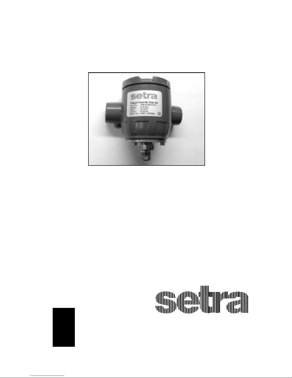
Model 256
Gage Pressure Transducer

Industrial
HVAC
Test &Measurement
Barometric
UltraHighPurity/Sanitary
Setra offers a complete line of
products for these industries:

Table of Contents
1.0 GENERAL INFORMATION............................................................................................... 4
2.0 MECHANICALINSTALLATION ...................................................................................... 4
2.1 MediaCompatibility.......................................................................................... 4
2.2 Environment......................................................................................................... 4
2.3 Pressure Fittings .................................................................................................. 4
2.4 Moisture Precautions ........................................................................................ 4
2.5 Venting ................................................................................................................... 4
2.6 Mounting Accessories....................................................................................... 5
3.0 ELECTRICAL INSTALLATION.......................................................................................... 5
3.1 Voltage Output Units......................................................................................... 5
3.2 Current Output Units ........................................................................................ 6
4.0. CALIBRATION .................................................................................................................... 6
4.1 Voltage Output Zero Adjustment ................................................................. 6
4.2 Voltage Output Span Adjustment ................................................................ 7
4.3 Current Output Zero Adjustment................................................................. 7
4.4 Current Output SpanAdjustment................................................................ 7
5.0 MODEL 256 PERFORMANCE SPECIFICATIONS....................................................... 7
6.0 RETURNING PRODUCTSFORREPAIR......................................................................... 8
7.0 WARRANTY AND LIMITATION OF LIABILITY............................................................ 8

4
Setra Model 256
PressureTransducer
1.0 GENERAL INFORMATION
Every Model 256 has been tested and calibrated before shipment. Specific
performance specificationsare listed on Page 7 ofthis Guide.
Setra Systems 256 pressure transducers sense gage pressure and convert this
pressureto aproportional high levelanalog output. Two output versionsare
offered: Avoltageoutputof .1to 5.1VDC,andacurrent outputof 4to 20 mA.
2.0 MECHANICAL INSTALLATION
2.1 Media Compatibility
Model 256 transducers are designed to be used with any gas or liquid compat-
ible with 17-4 PH Stainless Steel. (Hydrogen is not recommended for use with
17-4PH SS.)
2.2 Environment
The operating temperature limits of the 256 are as follows:
OperatingTemperature Range °F (C°) -40to +260 (-40 to +125)
CompensatedTemperature Range°F (C°) -4 to +176 (-20 to +80)
2.3 Pressure Fittings
Typically,standard pipefittings andinstallationproceduresshouldbeused.
However,forvery high pressure ranges in excessof 500 psig,we suggest the
use of a sealant such as Loctite Hydraulic Sealant. Excessive high torquing of
metal fittings may cause a slight shift of the output,but this shift can be
trimmed out by the zero adjustment. Torquingdoesnot significantly affect
linearityor sensitivity.
2.4 Moisture Precautions
The Model 256 is provided with two 1/2”NPT female conduit ports for electrical
termination. These tapered pipe threads are tapped deeper than the NPT
standard,in accordance with industry guidelines. These ports must be sealed
according to standard industry practice,in order to prevent moisture ingress
intothe Model 256.
2.5 Venting
TheModel256 is a true gagepressuretransducer. Thismeans that the
reference side of the pressure sensing diaphragm must be vented to atmo-
sphere. Ifthe reference side of the diaphragm weresealed (asin a sealed gage
transducer),temperaturechanges wouldcausethe referencepressuretovary.
Thismayaffectthe overallaccuracy,especiallyin ranges lowerthan 500 psig.
The Model 256 provides a vent from the reference side of thesensor to the
insideof the housing and the conduit ports. The user-providedelectrical
conduit must be vented to atmosphere in a clean dry location. (It is important
to prevent moisture ingress from the environment into the wiring chamber
or reference side of the transducer.)

+EXC
EXC
GND
OUT
+ OUT
Voltage Connections
Current Connections
Screw Terminal
Designations
Diagram 1
+EXC
EXC
GND
Diagram 2
Removable
Zero/Span
Access Plugs
Removable
Terminal Block
Connector
5
3.1Voltage Output Units
The Model 256 is a 3-wire circuit. The -EXC and -OUT are commoned on the
circuit. The 256 can operate from a 12 to 28VDC excitation. The 256 has a 0.1-
5.1VDC output.
+ Excitation;connect to 12-28VDC powersupply
+ Output;connect to controller or monitor
–Output;connect to controller or monitor
–Excitation;connect to return of 12-28V power supply
GND Connect to system or earth ground
The Model 256can be wiredas a threewire deviceby connecting –output,
excitationand shield to a common ground.However,accuracywill be reduced
with increase in lead resistance.
2.6 Mounting Accessories
TheModel256 is providedwith a bracket and
twohexboltsformounting and a1/2”NPT plug
for the unused conduit opening.The bracket is
suitable for mounting with a U-bolt or a band
clamp.There are1/4-20 UNC threadedholes on
theback of the 256 transducer fordirect mounting
and/orgrounding.
3.0 ELECTRICAL INSTALLATION
Wiring is through a 1/2”conduit opening. Remove the
screw cover to access the removable wiring terminal
block connector. The terminal block connector version
has five terminals for wiring +EXC,-EXC,GND,-OUT,and
+OUT(see Diagram1).
Removetheterminal blockconnector to facilitatewiringto screwterminals.
Refer to the terminal block connector label for terminal designations. (See
Diagram 2 for screw terminal designations.) After wiring,plug connector back
into pin socket and neatly tuck all wiring into wire recess cavity.

3.2 Current Output Units
The 4-20 mA current output units are designed to have current flow in one
direction only -PLEASEOBSERVEPOLARITY.
We suggest that the electrical conduit shield be connected to the system’s loop
circuit ground to improve electrical noise rejection.
The Model 256 is a two-wire loop-powered 4 to 20mA current output unit and
delivers rated current into any external load of 0-800 ohms.(See Diagram 2 for
location of +EXC and -EXC current output screw terminals.) The current flows
into the + terminal and returns back to the power supply through the
-terminal.(ThecenterGND terminal maybe used for shielding.) The power
supplymust be a DC voltage sourcewith a voltagerange between9 and 30
measured between the + and - terminals. The unit is calibrated at the factory
witha 24VDC loop supply voltageand a 250 ohm load.
Minimum SupplyVoltage(VDC)= 9+ 0.02x (resistanceofreceiverplus line).
Maximum SupplyVoltage (VDC) =30 +0.004 x(resistanceof receiverplus line).
4.0 CALIBRATION
The 256 transducer is factory calibrated and should require no field
adjustment. Whenever possible,any zero and/or span offsets should be
corrected by software adjustment in the user’s control system. However,both
zero and span adjustments are accessible by removing the screw top cover and
theadjustment accesscoverand turningthe potentiometer screw inside.(See
Diagram 1 for the location of the Zero and Span potentiometers.)
4.1 Voltage Output ZeroAdjustment
While monitoring the voltage between the positive output (+OUT) and
negativeoutput (–OUT),and with the pressureportopen toatmosphere,or
with zero pressure applied,the zero may be adjusted by turning the zero
potentiometerscrew. The factorysetting is0.1VDC (±25mV).
Note:–OUT and –EXC are commoned on the circuit.
4.2 Voltage Output Span Adjustment (Complete the zero adjust-
mentbeforesetting span.)
Span or full scale output adjustments should only be performed by using an
accuratepressure standard(electronicmanometer,digitalpressuregage,etc.),
with at least comparable accuracy to the 256 transducer. With full
range pressure applied to the pressure port,the span may be adjusted by
turning the span potentiometer screw. The factory setting is 5.1VDC (±50mV).
6

4.3 Current Output Zero Adjustment
While monitoring the current output,and with the pressure port open to
atmosphere or with zero pressure applied,the zero may be adjusted by turning
the zero potentiometer screw. The factory setting is 4mA (±.08mA).
4.4 Current Output Span Adjustment
Span or full scale output adjustments should only be performed by using an
accurate pressure standard (electronic manometer,digital pressure gage,etc.)
with at least comparable accuracy to the 256 transducer. With full range
pressure applied to the pressure port,the span may be adjusted by turning the
spanpotentiometerscrew. The factorysetting is 20mA (±.16mA).
5.0 MODEL 256 PERFORMANCE SPECIFICATIONS
For Ranges For Ranges
25 PSI and Higher Less Than 25 PSI
AccuracyRSS*(atconstanttemperature.) ±.13%FS ±0.25%FS
Non-Linearity,BFSL ±0.1%FS ±0.22%FS
Hysteresis 0.08%FS 0.10%FS
Non-Repeatability 0.02%FS 0.05%FS
*RSSofNon-Linearity,Non-RepeatabilityandHysteresis.
ThermalEffects
CompensatedRange°F(°C) -4to+176(-20to+80) -4to+176(-20to+80)
ZeroShift%FS/100°F(50°C) ±1.0(±0.9) ±2.0(±1.8)
SpanShift%FS/100°F(50°C) ±1.5(±1.4) ±1.5(±1.3)
Warm-upShift ±0.1%FStotal ±0.1%FStotal
7

8
6.0 RETURNING PRODUCTS FOR REPAIR
Pleasecontact a Setra Systemsapplication engineer (1-800-257-3872,1-978-263-1400)
beforereturningunit forrepairtoreview informationrelativetoyour application.
Many times only minor field adjustments maybe necessary.When returning a product
toSetra Systems,thematerialshould be carefully packaged and shipped prepaidto:
Setra Systems,Inc.
159Swanson Road
Boxborough,MA 01719-1304
Attn:Repair Department
To assure prompt handling,please supply the following information and include it
insidethe packageor returnedmaterial:
1. Name and phone number of person to contact.
2. Shippingand billing instructions.
3. Full description of the malfunction.
4. Identify any hazardous material used with product.
Notes: Please remove any pressure fittings and plumbing that you have installed and
enclose any required mating electrical connectors and wiring diagrams.
Allowapproximately 3 weeks after receiptat SetraSystemsforthe repair and return of
theunit.Non-warrantyrepairs will not be made without customerapprovaland a
purchase order to cover repair charges.
CalibrationServices
Setra maintains a completecalibration facility that is traceable to the National Institute
of Standards &Technology (NIST). If you would like to recalibrate or recertify your
Setra pressure transducers or transmitters,please call our Repair Department at 800-
257-3872(978-263-1400) for scheduling.
7.0 WARRANTY AND LIMITATION OF LIABILITY
SETRAwarrantsitsproductstobefreefromdefectsinmaterialsandworkmanship,subjecttothefollowingtermsandconditions: Withoutcharge,SETRAwillrepairorreplace
productsfoundtobedefectiveinmaterialsorworkmanshipwithinthewarrantyperiod;providedthat:
a) theproducthasnotbeensubjectedtoabuse,neglect,accident,incorrectwiringnotourown,improperinstallationorservicing,oruseinviolationofinstructions
furnishedbySETRA;
b) theproducthasnotbeenrepairedoralteredbyanyoneexceptSETRAoritsauthorizedserviceagencies;
c) theserialnumberordatecodehasnotbeenremoved,defaced,orotherwisechanged;and
d) examinationdiscloses,inthejudgmentofSETRA,thedefectinmaterialsorworkmanshipdevelopedundernormalinstallation,useandservice;
e) SETRAisnotifiedinadvanceofandtheproductisreturnedtoSETRAtransportationprepaid.
Unlessotherwisespecifiedinamanualorwarrantycard,oragreedtoinwritingandsignedbyaSETRAofficer,SETRApressureandaccelerationproductsshallbewarrantedfor
oneyearfromdateofsale.
Theforegoingwarrantyisinlieuofallwarranties,express,impliedorstatutory,includingbutnotlimitedto,anyimpliedwarrantyofmerchantabilityforaparticularpurpose.
SETRA’sliabilityforbreachofwarrantyislimitedtorepairorreplacement,orifthegoodscannotberepairedorreplaced,toarefundofthepurchaseprice. SETRA’sliabilityforall
otherbreachesislimitedtoarefundofthepurchaseprice. InnoinstanceshallSETRAbeliableforincidentalorconsequentialdamagesarisingfromabreachofwarranty,or
fromtheuseorinstallationofitsproducts.
NorepresentativeorpersonisauthorizedtogiveanywarrantyotherthanassetoutaboveortoassumeforSETRAanyotherliabilityinconnectionwiththesaleofits
products.
SS2033 Rev.F 02/04/02
159SwansonRoad,Boxborough,MA01719
TollFree:(800)257-3872,Fax:(978)264-0292
Table of contents
Other Setra Systems Accessories manuals


Popular Accessories manuals by other brands


WBOX Technologies
WBOX Technologies 0E-PIRCM Installation

Waeco
Waeco ColdMachine 54 operating manual

Invisible systems
Invisible systems QC0161 installation manual

aci
aci Room Series Installation & operation instructions

Tait
Tait TB7100 Installation and operation manual

Xantech
Xantech 172-94X installation instructions


