User Manual
6
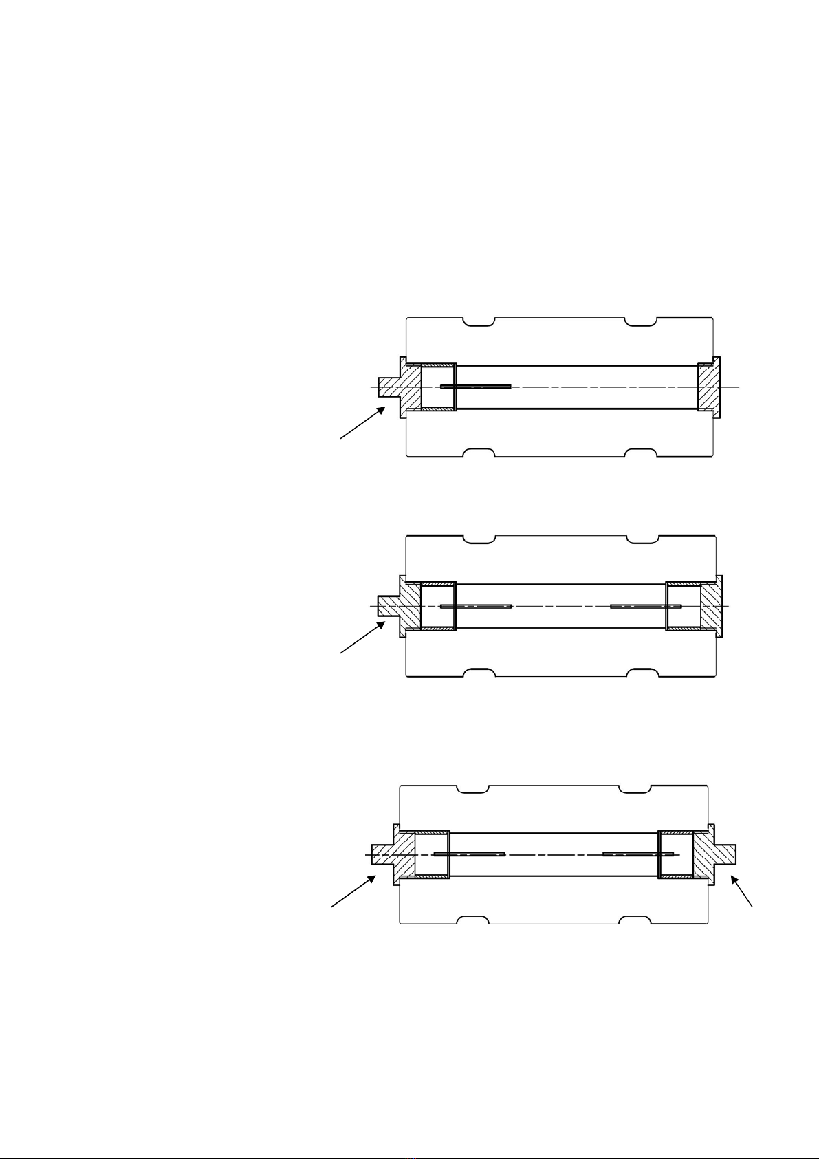
Load cell connection
The load cell single or double strain gauge bridge outputs shall be connected using
shielded cable. It shall than be connected to the measuring equipment bridge mV/V
input signal channel
The bridge power shall be connected to E+ and E- outputs and the measuring equipment signal
input shall be connected to the S+ and S- outputs.
The cable should be routed at least 100 mm from other cables, so that electromagnetic
interference is avoided. Cable shield is not connected to the load cell body and shall be
grounded in the other end. The load cell connector housing is connected to the load cell
body and the cable shield shall not be connected in the cable connector but be grounded
in the other end. Cable shield is then grounded in one point only.
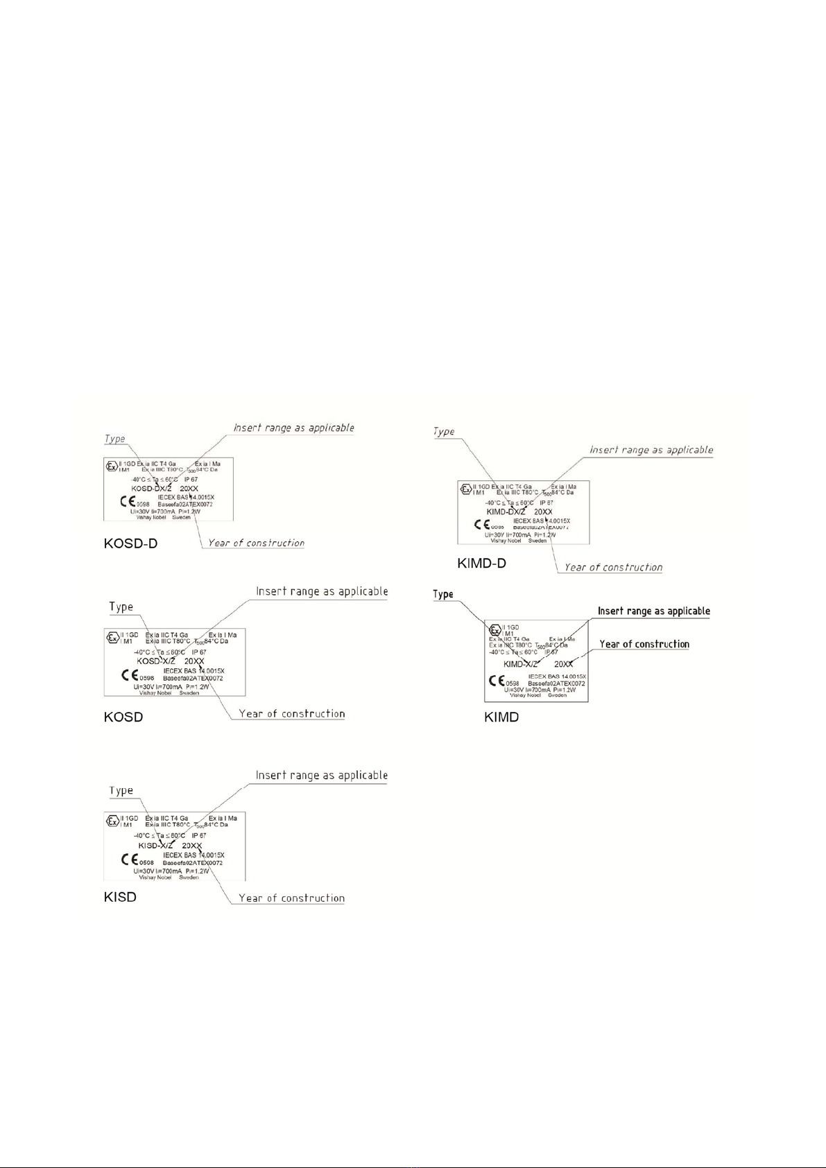
For installation in an explosive gas/dust or mining area, only trained personnel may
perform dimensioning of cables and barriers. A descriptive system document should be
prepared by the system designer.
* Deviations may occur in customer specific types.
Connector pin-out and wires color code:
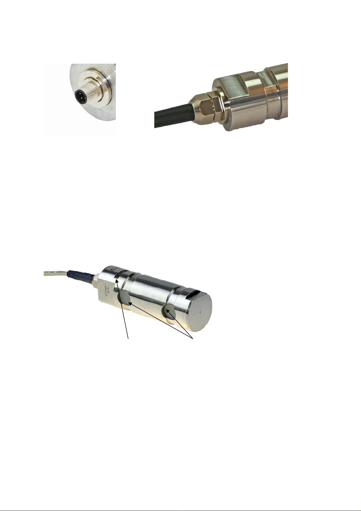
Electrical connection
Connector type: (M12 or equivalent IP67 qualified)
Cable: Shielded 4 or 8-wire 0,25mm2 cable through IP67 qualified cable gland
Connector pin number *
Pin 1: E+ (positive excitation). Bridge 1
Pin 3: S+ (positive signal). Bridge 1
Pin 2: S- (negative signal). Bridge 1
Pin 4: E- (negative excitation). Bridge 1
Pin 5: E+ (positive excitation). Bridge 2
Pin 7: S+ (positive signal). Bridge 2
Pin 6: S- (negative signal). Bridge 2
Pin 8: E- (negative excitation). Bridge 2
Cable: Cable wire colour *
Red: E+ (positive excitation). Bridge 1
Green: S+ (positive signal). Bridge 1
White: S- (negative signal). Bridge 1
Grey: E- (negative excitation). Bridge 1
Brown: E+ (positive excitation). Bridge 2
Blue: S+ (positive signal). Bridge 2
Yellow: S- (negative signal). Bridge 2
Pink: E- (negative excitation). Bridge 2