Geotech PRS User manual

Rev 3/17/2017 Part # 26600008
Geotech Product
Recovery System
Installation and Operation Manual


1
Table of Contents
DOCUMENTATION CONVENTIONS.......................................................2
Section 1: System Description..............................................................3
Function and Theory ......................................................................................... 3
Specific Gravity and Viscosity Limitations......................................................... 4
System Components......................................................................................... 4
Section 2: System Installation.............................................................10
Planning Your PRS Installation.......................................................................10
Install Control Panel ........................................................................................10
Install the Pump and Skimmer to the well....................................................... 10
Section 3: System Operation...............................................................13
Section 4: System Maintenance..........................................................14
Weekly Maintenance.......................................................................................15
Monthly Maintenance ...................................................................................... 15
Quarterly Maintenance.................................................................................... 16
Yearly Maintenance......................................................................................... 16
Cleaning the Skimmer and Intake Screen....................................................... 16
Conditioning the Intake Screen.......................................................................16
Bladder Replacement...................................................................................... 16
Section 5: System Troubleshooting....................................................18
Section 6: System Specifications........................................................20
Section 7: System Schematic..............................................................23
Section 8: Replacement Parts List......................................................24
The Warranty........................................................................................33

2
NOTE
DOCUMENTATION CONVENTIONS
This uses the following conventions to present information:
An exclamation point icon indicates a WARNING of a situation
or condition that could lead to personal injury or death. You
should not proceed until you read and thoroughly understand the
WARNING message.
WARNING
CAUTION
A raised hand icon indicates CAUTION information that relates to
a situation or condition that could lead to equipment malfunction
or damage. You should not proceed until you read and thoroughly
understand the CAUTION message.
A note icon indicates NOTE information. Notes provide additional
or supplementary information about an activity or concept.

3
Section 1: System Description
Function and Theory
The Geotech Product Recovery System (PRS)
efficiently collects free-floating hydrocarbons in
2” (5 cm) or larger recovery wells. The system
consists of a stainless steel bladder pump, an
attached Skimmer with floating intake cartridge
(or buoy), a control panel that can be mounted
indoors or out, an optional Tankfull Shut-off
Sensor, air and discharge lines, and an
optional air compressor.
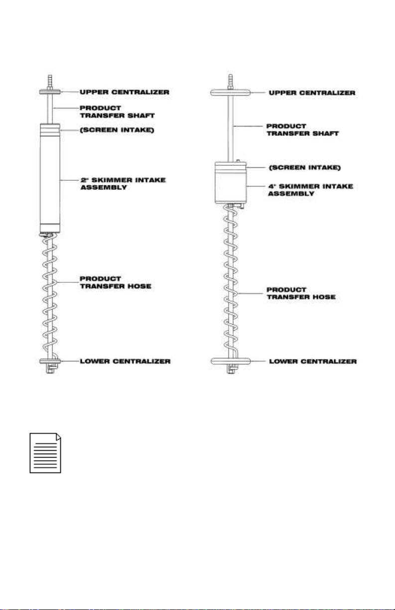
The PRS’ unique product intake assembly, or
Skimmer, incorporates both a density float and
an oleophilic/hydrophobic filter that
differentiates between floating hydrocarbons
and water. The intake assembly follows the
water table fluctuations and places the screen
at the water/product interface, skimming light
product (such as gasoline or diesel fuel) down
to a sheen within the range of the float travel.
As the system cycles, product is drawn
through the intake screen and is transferred to
the pump through a coiled hose and the
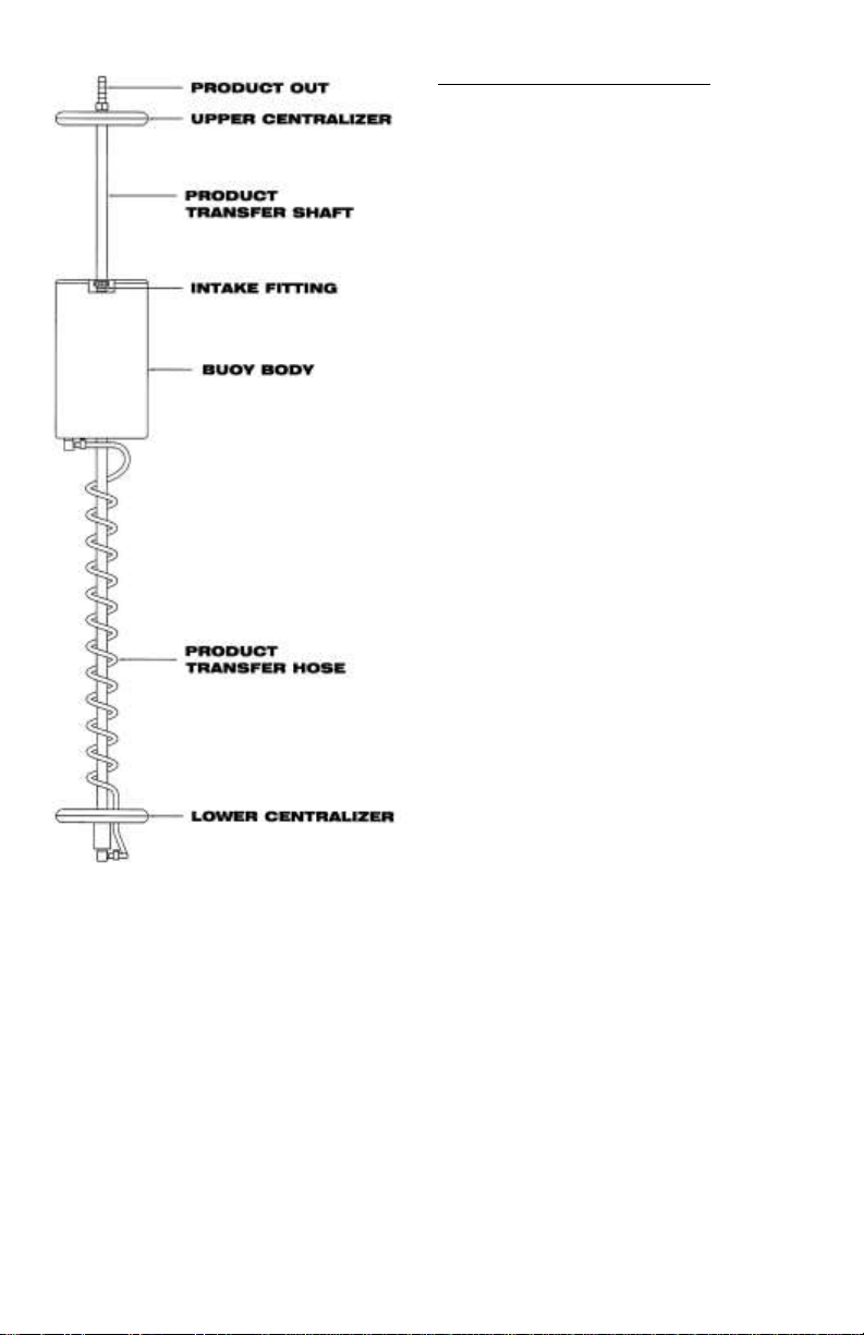
Skimmer’s transfer shaft. Optional Heavy Oil
and High Temperature Skimmers, using intake
buoys, are also available to recover product in
4” (10 cm) diameter and larger wells.
The Product Recover System Control Panel
regulates the system and features two timers,
which vary the cycle time and flow rate of the
Skimmer pump. The control panel also
contains a level control valve (to which the
Tankfull Shut-off Sensor connects) that will
shut off the pump when the recovery tank is
filled.
The automatic stainless steel bladder pump has a two-phase pumping cycle. During the
first phase, or “pump intake”phase, pressurized air is vented from the pump, thus creating
a vacuum. This vacuum closes the top discharge check valve and opens the bottom
intake check valve, causing product to be drawn through the Skimmer’s product intake
assembly and into the pump.
During the second phase, or pump “discharge phase”, pressurized air is directed into the
pump bladder, causing it to expand within the pump body. This action closes the bottom
Figure 1-1: PRS Pump

4
intake check valve and opens the top discharge check valve, thus forcing the recovered
product from the pump up to the surface.
Specific Gravity and Viscosity Limitations
The specific gravity of the product to be recovered must be less than 1.0 and its viscosity
less than 50 SSU for use with the “light” oil filter, and 400 SSU for use with the “heavy” oil
filter cartridge. Consult Geotech for product recovery operations with viscosities outside
that range.
This type of filter technology is designed to be used in wells with free product of at least
1/8” (3 mm) thickness.
The presence of surfactants or detergents in the product requires careful application.
When handling these contaminants please consult Geotech.
System Components
Pump
The PRS utilizes an air driven bladder pump. The pump
consists of a stainless steel outer housing, top and
bottom check valves, and a flexible inner bladder. The
pump is designed for pumping liquids only; any solids
(silt, dirt, etc.) may reduce its performance or cause the
pump to malfunction.
Skimmer Attachments
A standard Skimmer attachment (when connected to the
stainless steel pump assembly) is designed for use in
either 2” (5 cm) diameter wells or 4” (10 cm) diameter
and larger wells. Figure 1-2 and 1-3 show an example of
the two most common Geotech Skimmers. These
Skimmers come with a standard 100-mesh intake
screen. A 60-mesh intake screen is also available for use
with higher viscosity fluids. See Geotech Manual
“Hydrocarbon Viscosity Test Kit” for more information on
choosing the correct intake cartridge.
The Skimmer assembly is connected to the bottom of the
stainless steel pump with a 6” (15 cm) piece of durable,
fuel grade hose. The Skimmer consists of a product
intake float, a coiled product transfer hose, and a transfer
shaft. Well centralizers are placed at the top and bottom
of the Skimmer shaft to protect the intake float and to
allow unobstructed travel within the well. To
accommodate water level fluctuations, standard 2”
Skimmers can provide 12” (30 cm) of intake travel and
standard 4” Skimmers can provide 16” (40 cm) of intake
travel.
Figure 1-2: PRS Pump
shown with 2” Skimmer
Assembly

5
A Skimmer assembly will not draw water unless the intake cartridge
is forcibly submerged, surfactants are present, or when the
“conditioning” of the intake screen has been removed. See Section
4: System Maintenance for information on rec-conditioning the
intake screen.
Figure 1-3: Standard 2” and 4” Skimmer Attachments

6
Heavy Oil Skimmer Attachment
The optional Heavy Oil Skimmer
attachment is designed to recover a
range of fluids from gasoline to gear oil,
skimming the product down to .01’ (3
mm) in 4” (10 cm) diameter and larger
wells. This option is best suited when
the viscosity of the hydrocarbon is
greater than the capability of the filter
screen technology (screen can no
longer pass the hydrocarbon fluid).
The Heavy Oil Skimmer consists of a
polypropylene intake buoy, a coiled
product transfer hose, and a transfer
shaft with well centralizers placed at the
top and bottom. The intake buoy on the
Heavy Oil Skimmer is designed to “ride”
at the oil water interface and has a
travel range of 24” (61 cm).
The intake buoy can also be “fine-
tuned” by adjusting the intake fitting on
the top of the buoy. Turning the fitting
clockwise will lower the intake fitting
relative to the product/water interface.
Turning the fitting counter-clockwise will
raise the intake fitting away from the
interface. Figure 1-4 is an example of a
Heavy Oil Skimmer assembly.
Figure 1-4: Heavy Oil Skimmer
Attachment (optional)

7
PRS System Control Panel (Optional)
The air-driven pump controller is the core component of the Product Recovery System.
The controller uses two timers to vary the pumping rate of the system, independently
controlling the discharge time and the recharge time of the pump. A clean, dry air source
that can deliver one cubic foot per minute (cfm) at 90 PSI (or .03 cmm at 6 bar) will
adequately allow the controller to drive one pump. Up to four pumps can be run from one
controller with a commercial air supply of at least 4 CFM (.11 CMM) at 90 PSI (6 bar).
The PRS Control Panel comes equipped with a Tankfull Shut-off feature. The Tankfull
Shut-off incorporates a manual reset button as an additional safety feature. When the
product recovery tank becomes full, the Tankfull Shut-off Sensor shuts off the system. The
system must be manually reset in order to resume operation.
The Tankfull indicator is green when the system is operational and is black when the
system is off. The recovery tank must be emptied and the control panel manually reset
before the system can be reactivated, and the indicator to show green.
Figure 1-5: PRS System Control Panel

8
Tankfull Shut-off Sensor (Optional)
The Tankfull Shut-off Sensor assembly (Figure 1-6) consists of a sensing tube that is
connected to the control with a sensor airline. The control needs to be within 50’ (15 m) of
the discharge tank.
When the product rises approximately 11”(28 cm) up the side of the sensing tube, the
level control valve within the control panel shuts off air supply to the pump. Once the tank
is drained, the system can be reset and resume normal operation.
Figure 1-6: Example of the Tankfull Shut-off Sensor (recovery tank not supplied)
Air Line and Discharge Hoses
Typically, conduit or 2” (5 cm) PVC pipe, buried below grade, should be used to protect
the air and discharge lines from damage. Failure to safeguard the air and discharge lines
may lead to uncontrolled pump discharge and/or compressor failure. The discharge port of
the pump accepts standard 1/4” NPT and 1/2” FPT pipe threads. Check government
regulations regarding fuel transmission lines before installation of product discharge lines.
The dimensions of airline and hose to the listed devices are as follows:
Compressor 3/8” O.D. x 50’ / 9.5mm x 15m
Pump Air Line 1/4” O.D. x 100’ / 6mm x 30m
Product Discharge Line 5/8” O.D. x 100’ / 16mm x 30m
Controller to Tank Full Shut off Sensor 1/4” O.D. x 50’ / 6mm x 15m

9
Product Recovery Tank (Purchased Separately)
A product recovery tank with a 2” NPT bung opening for the Tankfull Shut-off Sensor tube,
a product inlet opening, and a vent are required for proper operation –typically a 55 gallon
(208 liter) drum or other suitable container. Check government regulations regarding fuel
storage before selecting a recovery tank.
Air Compressor (Purchased Separately)
Refer to instructions provided with the air compressor for installation procedures. An
automatic tank drain and an air dryer may be required for the air compressor if the system
is operating in humid conditions. Bottled air may be used to operate the SpOILer System if
operating an air compressor is not feasible. A high-pressure regulator must be used to
reduce the air pressure to the range of 60 PSI (4 bar) to 100 PSI (7 bar). Pressures
outside of this range may cause the system to malfunction.

10
Section 2: System Installation
Planning Your PRS Installation
To successfully plan the installation of the PRS, use the following guidelines to determine
a suitable location for the control panel, pump, air compressor, Tankfull Shut-off Sensor,
and recovery tank. Also, refer to the System Schematic found in Section 7: System
Schematics.
The standard PRS is not supplied with an air compressor. When installing an air
compressor, do not locate the compressor in areas where there may be explosive
vapors. Compliance with Section 5 of the U.S. National Electric Code Handbook and
any local codes is essential for an electrically safe installation.
The product recovery tank should be located within 50’ (15 m) of the control panel
when the Tankfull Shut-off Sensor is used.
All airline connections must be installed properly for the system to function correctly.
When cutting the airline, the cut must be clean and square. When inserting the
airlines into the compression fittings, push the airline firmly into the fitting, hand
tighten the compression nut, and then tighten one more full turn with a wrench.
Install Control Panel
Install control panel vertically on hard surface or post.
Install the Pump and Skimmer to the well
1. Remove the inner ring of the well cap and secure it to the well casing using the three
set screws located on the perimeter of the ring (for systems using a well cap).
2. Measure and cut a length of the provided airline and connect it from the output of the
air compressor to the port labeled INPUT FROM AIR SUPPLY on the control panel.
To calculate the amount of air line and discharge hose required to suspend the
pump and Skimmer in the well, first determine the static water level in the well,
then subtract 46” (117 cm), 38” (97 cm) for the 2” Skimmer, from the reading.
DO NOT make any cuts to tubing until all measurements have
been made.
Prior to installation, condition the intake screen with diesel fuel or a
similar hydrocarbon. For optimum performance, use the same down
well hydrocarbon to be recovered. In order to avoid damage, condition
the intake screen using a soft bristle brush.

11
3. Pull the measured lengths of airline and discharge hose through the fittings on the
well cap.
4. Fully tighten the compression fittings.
The well cap will suspend the pump and Skimmer by the discharge hose, setting
the intake assembly at the midpoint of its travel range.
5. Attach the airline and discharge hose to the pump using the provided compression
fitting and hose clamp respectively, and set the pump and Skimmer in the well.
6. Connect the free end of the pump airline to the controller fitting labeled OUTPUT TO
PUMP.
7. Connect the free end of the product discharge hose to the product recovery tank.
8. Install the Tankfull Shut-off Sensor airline between the Tankfull Shut-off Sensor tube
and the controller fitting labeled INPUT FROM TANKFULL SHUT-OFF SENSOR.
Tankfull Shut-off Installation
Install the sensing tube in the 2” NPT bung opening on the discharge tank.
Test Tankfull Shut-off Sensor
1. Test the Tankfull Shut-off Sensor by immersing the sensor tube in a pail of water (at
least 12” (30 cm) deep) while the system is cycling.
Within one cycle, the sensor will shut off the air supply to the control panel.
2. When the sensing tube has been removed from the water, test to be sure the system
remains off until the reset is pressed.
If the system does not function as described, check the fittings at both the
controller and sensing tube, and check for kinks in the sensor airline.
See Figure 2-1 for a view of the pump and Skimmer in relation to
the well cap and static water level.

12
Figure 2-1: Pump and Skimmer Assembly

13
Section 3: System Operation
1. Start the air compressor. Refer to air compressor manual for operation instructions.
2. Verify that the controller’s pump intake and pump discharge timers are on the “C”
setting as indicated on the controller faceplate.
3. Turn the air valve on the control panel to the “ON” position.
The system will now begin to cycle and recover product.
The pumping rate can be adjusted based on product volume. If there is a large volume of
product, or a minimal amount of product in the well, the pumping rate may be adjusted by
referring to the following illustrations.
A. Normal (default) setting
B. Maximum pumping rate
C. Minimum pumping rate
Figure 3-1: PRS Dials
DO NOT USE THE SETTINGS WITHIN THE SHADED AREA ON
THE DIALS. Refer to Figure 3-1 for help with configuring the PRS
dials.

14
Tankfull Shut-off Sensor
A minimum of 45 PSIG (3 bar) air pressure is required for operation.
When liquid level rises 11” (28 cm) up the pressure tube, the valve closes shutting off
compressed air to the system.
When an alarm is triggered the recovery tank must be emptied. Once the recovery
tank is drained, a manual reset on the control panel is required to resume system
operation.
The pumping rate may be reducing the system air pressure. 45 PSI
(3 bar) minimum to 60 PSI (4 bar) is required to operate bladder
pump.

15
Section 4: System Maintenance
Weekly Maintenance
Turn the air compressor off and drain the air tank(s). On air compressors without
an optional automatic condensate drain, open the drain fitting on the bottom of
the compressor tank(s) and drain any accumulated water. The tank(s) must be
drained regularly to avoid compressor malfunction.
Check and adjust the compressor.
Inspect the compressor for loose fittings. Over time, vibration may cause bolts to
loosen or air leaks to develop. If uncorrected, excess air consumption and
shortened compressor life will result.
Verify pump settings and fluid levels in the well. Make sure that the pump and
Skimmer are set at the correct interval for collection of free product.
Monthly Maintenance
Pull the pump and Skimmer from the well.
Inspect all tubing for cracks, kinks and damage. Replace any old and brittle
tubing.
Inspect the coiled tubing for physical damage or obstructions. Verify the intake
assembly moves freely over its travel range.
Inspect the float (buoy) and intake screen. Clean the intake screen and float
using the method described in this section.
Inspect the Skimmer assembly for signs of physical damage. Scrapes or dents in
the screen intake may cause the Skimmer to take on water. If such damage is
found, a new 2” or 4” intake assembly may be necessary.
Clear away any debris collected in the well vault (or above ground casement).
Measure the well and record product layer thickness and depth to water from top
of well casing.
Place a pump positioning mark or zip tie on the discharge hose (usually black)
even with the top of well casing.
Re-deploy pump, aligning new depth to water mark on discharge hose with top of
well casing.
Check the Tankfull Shut-off sensor for proper operation.
Always ensure all hose and tubing fittings at the pump and
between the pump and Skimmer are tight prior to deploying the
unit into the well.

16
Quarterly Maintenance
Pull pump and Skimmer from the well.
Clean the well screen (site specific, primarily to clear bio growth and keep thick
degraded product from impeding conductivity to the well at the product layer.
Frequency to be determined by user).
Place float assembly in water to verify the screen stays out of the water at the top
of the traverse range. If it does not, replace the coiled tubing and retest. If it still
does not, replace the float assembly.
Yearly Maintenance
Pull the pump and Skimmer from the well.
Open pump and clean interior and parts with soapy water.
Degrease the check disk and check ball seats. Spray with silicone based
lubricant or kerosene.
Clean and prime intake screen using the method described in this section.
Cleaning the Skimmer and Intake Screen
Standard 2” and 4” Skimmers will usually come with a float containing a 100 or 60-mesh
intake screen. When required, gently clean the screen with a silicone based lubricant or
kerosene, using a soft bristle brush, to remove emulsified product, bio growth or other
debris. Take care to avoid damaging the screen intake. Rinse the product intake assembly
with clean water and make sure it is completely dry before reconditioning the intake
screen.
For Heavy Oil Skimmers, first use warm, soapy water, followed by silicone-based lubricant
or kerosene to remove debris or bio growth from the buoy body, then rinse and let dry.
Using warm, soapy water, clean all debris and bio growth from the Skimmer shaft and
coiled tubing.
Conditioning the Intake Screen
Prior to initial deployment, and after every cleaning, the intake screen must be conditioned
(or primed) with diesel fuel or other similar hydrocarbon. Use a soft bristle brush to
saturate the screen portion of the intake thoroughly. Prime the intake screen with diesel
fuel or a similar hydrocarbon. For optimum performance, use the same down well
hydrocarbon to be recovered. In order to avoid damage, prime the intake screen using a
soft bristle brush.
Bladder Replacement
The pump is fitted with a field replaceable bladder for easy repair on the job site (see
Figure 8-1).
1. Remove the lower pump housing from the upper control housing by unscrewing the
two parts.

17
2. Slide the lower housing off.
3. Unscrew the old bladder from the upper housing and screw on the new one.
The bladder can be tightened snugly by hand.
4. Re-attach the lower housing to the upper pump assembly.

18
Section 5: System Troubleshooting
Problem: The pump is only discharging water, not product.
Solutions:
The water level has risen above the travel range of the Skimmer.
Pull the pump and Skimmer out of the well. Purge the water out of the intake and
pump by allowing the system to cycle for several minutes, prime the intake
cartridge screen, then reset the pump and Skimmer.
The pump position has slipped, or the pump was installed below the water level in the
well.
Prime the intake cartridge screen, re-position the pump and Skimmer.
The intake assembly will not slide freely, or the coiled hose is tangled.
Inspect the Skimmer assembly and repair as necessary.
Loose hose or tubing on fittings below intake level.
Check all fitting connections.
Problem: The pump discharges air only, no product.
Solutions:
Product has been removed.
Reduce the pumping rate, or decrease the air pressure (45 PSI minimum) to
conserve air.
The Product layer is below the bottom of the Skimmer's travel range.
Reset the pump and skimmer.
The pump bladder has ruptured.
Replace the pump bladder or contact Geotech for further information.
Problem: The pump cycles but does not discharge product.
Solutions:
One or both of the pump check valves are malfunctioning.
Remove and clean, or replace the check valves.
The viscosity of the product is too thick for the Skimmer.
Contact Geotech for other Skimmer options.
The intake assembly is obstructed or the coiled product hose is kinked.
Verify that the intake assembly moves freely over its travel range, and adjust the
coiled hose if needed. Reset the pump and Skimmer.
Problem: The pump discharges air only, no product.
Solutions:
Product has been removed.
Table of contents
Popular Test Equipment manuals by other brands

Lutron Electronics
Lutron Electronics DL-9954 Operation manual

TEXIO
TEXIO DCS-7500A Series Programming manual

Agilent Technologies
Agilent Technologies InfiniiVision 3000 X- Series Advanced training guide

Chatillon
Chatillon TCM Series Operation manual

HOGERT
HOGERT HT8G430 user manual

Gallagher
Gallagher W810 v2 user manual