Gerus GERUPRESS HP27 User manual

GERUS
Bedienungsanleitung
GERUPRESS HP27
Operation manual
GERUPRESS HP27
001-025-000
GERUS Apparatebau GmbH & Co KG
Engelschalkstrasse 16
D-86316 Friedberg
e-mail: info@gerus-apparatebau.de Tel.: +49-0)821-588662-0
Fax: +49-0)821-588662-10

'Ͳ<ŽŶĨŽƌŵŝƚćƚƐĞƌŬůćƌƵŶŐ ͲĞĐůĂƌĂƚŝŽŶŽĨŽŶĨŽƌŵŝƚLJ
tŝƌĚŝĞ&ŝƌŵĂ tĞƚŚĞĐŽŵƉĂŶLJ
'Zh^ƉƉĂƌĂƚĞďĂƵ'ŵď, K<' 'Zh^ƉƉĂƌĂƚĞďĂƵ'ŵď, K<'
ŶŐĞůƐĐŚĂůŬƐƚƌĂƐƐĞϭϲϴϲϯϭϲ&ƌŝĞĚďĞƌŐ ŶŐĞůƐĐŚĂůŬƐƚƌĂƐƐĞϭϲϴϲϯϭϲ&ƌŝĞĚďĞƌŐ
ĞƵƚƐĐŚůĂŶĚ 'ĞƌŵĂŶLJ
ĞƌŬůćƌĞŶŚŝĞƌŵŝƚĚĂƐƐĚŝĞŶĂĐŚĨŽůŐĞŶĚ ĚĞĐůĂƌĞŚĞƌĞďLJƚŚĂƚƚŚĞĨŽůůŽǁŝŶŐĚĞƐĐƌŝďĞĚ
ďĞnjĞŝĐŚŶĞƚĞDĂƐĐŚŝŶĞĂƵĨŐƌƵŶĚŝŚƌĞƌ ŵĂĐŚŝŶĞŝŶŝƚƐĐŽŶĐĞƉƚŝŽŶĐŽŶƐƚƌƵĐƚŝŽŶ
<ŽŶnjŝƉŝĞƌƵŶŐƵŶĚĂƵĂƌƚƐŽǁŝĞŝŶĚĞƌǀŽŶ ĂŶĚĨŽƌŵƉƵƚďLJƵƐŝŶƚŽĐŝƌĐƵůĂƚŝŽŶŝƐ
ƵŶƐŝŶ ĞƌŬĞŚƌŐĞďƌĂĐŚƚĞŶƵƐĨƺŚƌƵŶŐ ŝŶĂĐĐŽƌĚĂŶĐĞǁŝƚŚĂůůƚŚĞƌĞůĞǀĂŶƚĞƐƐĞŶƚŝĂů
ĚĞŶĞŝŶƐĐŚůćŐŝŐĞŶ^ŝĐŚĞƌŚĞŝƚƐͲƵŶĚ ŚĞĂůƚŚĂŶĚƐĂĨĞƚLJƌĞƋƵŝƌĞŵĞŶƚƐŽĨƚŚĞ
'ĞƐƵŶĚŚĞŝƚƐĂŶĨŽƌĚĞƌƵŶŐĞŶĚĞŶŶĂĐŚͲ ĨŽůůŽǁŝŶŐĚŝƌĞĐƚŝǀĞƐ
ĨŽůŐĞŶĚĞŶĂŶŐĞĨƺŚƌƚĞŶ'ͲZŝĐŚƚůŝŶŝĞŶ
ĞŶƚƐƉƌŝĐŚƚ
DĂƐĐŚŝŶĞŶƌŝĐŚƚůŝŶŝĞϮϬϬϲϰϮ' DĂĐŚŝŶĞƌLJĚŝƌĞĐƚŝǀĞϮϬϬϲϰϮ
D ͲZŝĐŚƚůŝŶŝĞϮϬϬϰϭϬϴ' DĚŝƌĞĐƚŝǀĞϮϬϬϰϭϬϴ
ĞnjĞŝĐŚŶƵŶŐĚĞƌDĂƐĐŚŝŶĞ ƌƵĐŬůƵĨƚďĞƚƌŝĞďĞŶĞŚLJĚƌ,ŽĐŚĚƌƵĐŬƉƵŵƉĞ
ĞƐĐƌŝƉƚŝŽŶŽĨƚŚĞŵĂĐŚŝŶĞ ŝƌĚƌŝǀĞŶŚLJĚƌŚŝŐŚƉƌĞƐƐƵƌĞƉƵŵƉ
dLJƉ 'ZhWZ^^,WϮϳ
dLJƉĞ
^ĞƌŝĞŶͲEƌ ,WϮϳͲ
^ĞƌŝĂůEŽ
ŶŐĞǁĂŶĚƚĞŚĂƌŵŽŶŝƐŝĞƌƚĞEŽƌŵĞŶ EϭϮϭϬϬEϲϬϮϬϰ
ƉƉůŝĞĚŚĂƌŵŽŶŝnjĞĚƐƚĂŶĚĂƌĚƐ
ĞǀŽůůŵćĐŚƚŝŐƚĞƌĨƺƌƚĞĐŚŶŽŬƵŵĞŶƚĂƚŝŽŶ ŝƉů/ŶŐ,DƺƐĐŚĞŶďŽƌŶ
ƵƚŚŽƌŝnjĞĚƉĞƌƐŽŶĨŽƌƚĞĐŚŶĚŽĐƵŵĞŶƚĂƚŝŽŶ
KƌƚƵŶĚĂƚƵŵ &ƌŝĞĚďĞƌŐϬϮϬϴϮϬϭϮ
WůĂĐĞĂŶĚĚĂƚĞ
EĂŵĞƵŶĚWŽƐŝƚŝŽŶĚĞƐhŶƚĞƌnjĞŝĐŚŶĞƌƐ ŝƉů/ŶŐZ^ĐŚƌŽůů'ĞƐĐŚćĨƚƐĨƺŚƌĞƌ
EĂŵĞĂŶĚƉŽƐŝƚŝŽŶŽĨƐŝŐŶĞƌ ŝƉů/ŶŐZ^ĐŚƌŽůůƵƐŝŶĞƐƐŵĂŶĂŐĞƌ
hŶƚĞƌƐĐŚƌŝĨƚĚĞƐhŶƚĞƌnjĞŝĐŚŶĞƌƐ
^ŝŐŶĂƚƵƌĞŽĨƐŝŐŶĞƌ

REACH Erklärung REACH Declaration
Wir, die Firma We, the company
GERUS Apparatebau GmbH&CO.KG GERUS Apparatebau GmbH&CO.KG
Engelsc alkstrasse 16, 86316 Friedberg, Engelsc alkstrasse 16, 86316 Friedberg,
Deutsc land, Germany,
erklären hiermit, dass wir als Hersteller declare hereby that as a manufacturer of
von Maschinen und Werkzeugen zur machines and tools for overhauling and
Überholung und nstandsetzung von maintenance of large bore engines we
Großmotoren von der Verordnung nur are only concerned by the regulation as
als nachgeschalteter Anwender betroffen downstream user and, therefore, we are
sind und daher nicht zur Registrierung not bound to register or pre-register.
und Vorregistrierung verpflichtet sind.
Beim Gebrauch unserer Maschinen werden Under normal use of our machines, no
Keine Schadstoffe im Rahmen von Artikel harmful substances within the scope of
7.1 und 7.2 der Verordnung freigesetzt Article 7.1 and 7.2 of the regulation are
released.
Ort und Datum: Friedberg, 03.11.2011
Place and date:
Name und Position des Unterzeichners: Dipl. ng. R. Schroll, Geschäftsführer
Name and position of signer: Dipl. ng. R. Schroll, Business manager
Unterschrift des Unterzeichners
Signature of signer

HP27 GERUPRESS
Copyright by GERUS Apparatebau GmbH & Co.KG, Engelschalkstraße 16, D-86316 Friedberg
1. Funktionsbeschreibung
Das GERUPRESS stellt hohe statische Drücke zur Verwendung
in Kombination mit Hydraulikspannverschraubungen bereit.
Aufgrund seiner Spezifikation ist das GERUPRESS nicht zur
Förderung großer Volumina unter hohem Druck geeignet.
Weder Pumpenleistung noch Ölvorrat sind im ausreichenden
Maß für solche Aufgaben vorhanden. In ihrem spezifizierten
Anwendungsbereich kommt es mit dem Betriebsmedium
Druckluft aus.
Das Funktionsprinzip des GERUPRESS beruht auf einer
proportional wirkenden Druckpumpe. Der absolute maximale
Ausgangsdruck wird durch eine Sicherheitsbegrenzung auf der
Niederdruckseite gewährleistet (vgl. 1. Risikoanalyse).
Zum Betrieb wird die Pressluftversorgung (<15 bar) an die
GERUPRESS angeschlossen, die Anzeigen überprüft und der
Starthebel umgelegt. Der Druck wird bis zur eingestellten
Grenze aufgebaut. Der Arbeitsdruck kann über das
Druckbegrenzungsventil nachjustiert werden, bis der
gewünschte Wert auf dem Manometer angezeigt wird, oder der
Maximaldruck von 3000 bar erreicht ist.
Wird der Hochdruck nicht mehr benötigt, wird der Starthebel in
die „0“ Stellung zurück gebracht. Zum Entlüften der Leitungen
muss das manuelle Entlüftungsventil geöffnet werden. Die
Hochdruckleitungen können nur bei entlasteten Leitungen
abgebaut werden.
2. In- und Außerbetriebnahme
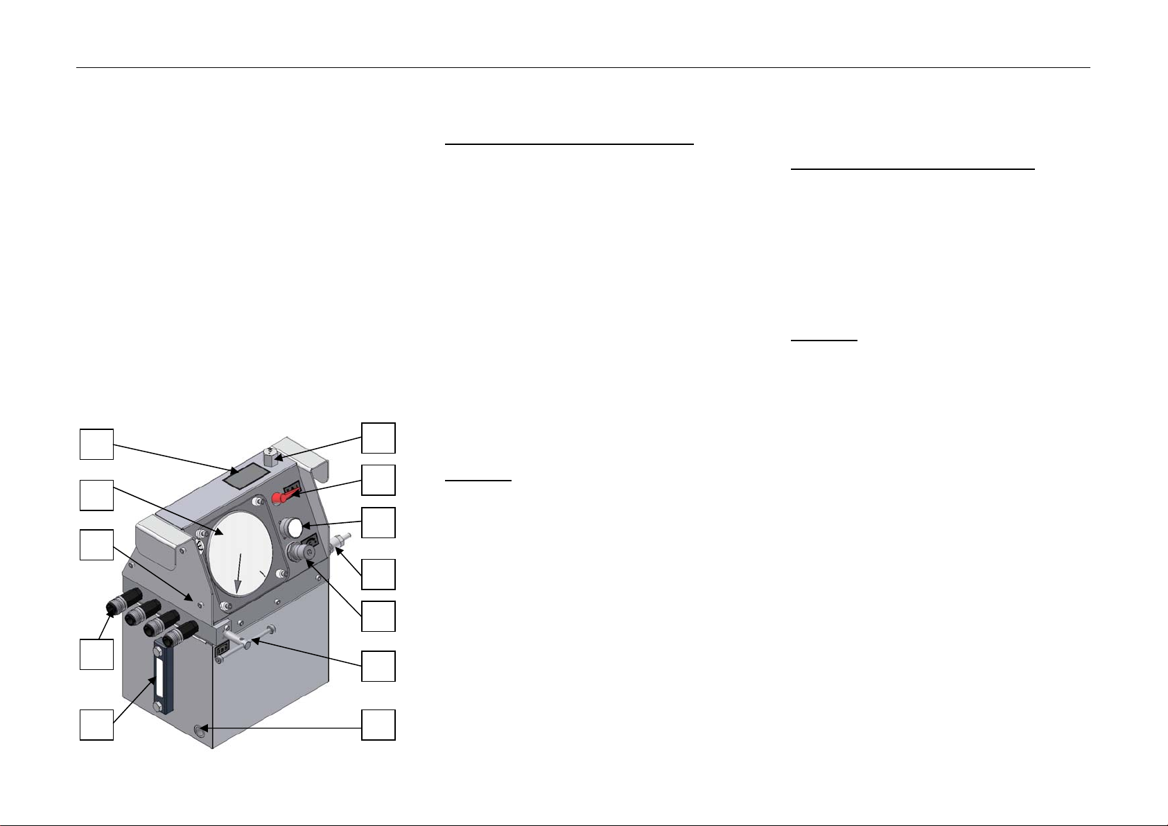
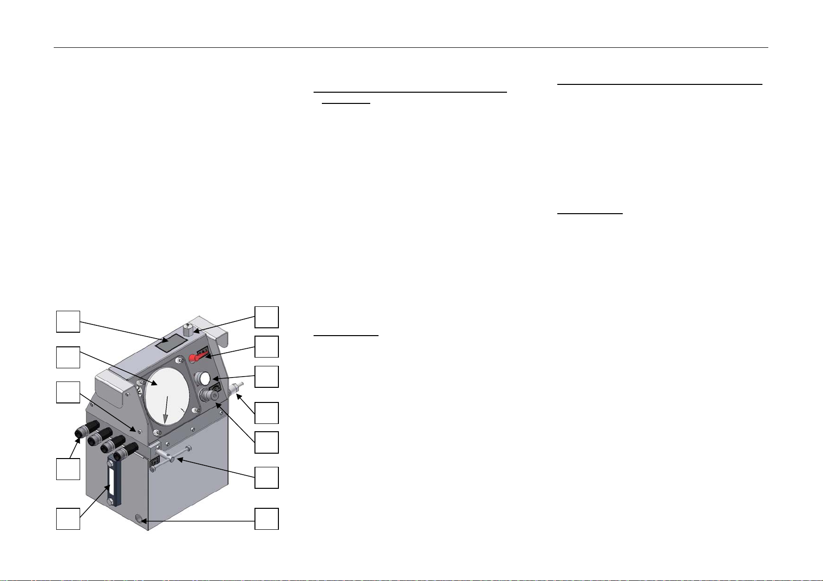
I. FUNKTIONSTEST DER HOCHDRUCKPUMPE
1.) Kontrollieren Sie die Anzeigegeräte Aund Iauf
Beschädigungen und Stellung der Zeiger. Beide
Zeiger sollten in 0-Stellung stehen.
2.) Kontrollieren Sie den Ölstand am Ölstandsanzeiger B
3.) Bei zu niedrigem Ölstand befüllen Sie das Gerät mit
Öl wie folgt:
4.1.) Wählen Sie die Ölqualität nach Vorgaben des
Hinweisschildes C
4.2.) Öffnen Sie den Öleinfüllstutzen Ddurch Drehung
einer halben Umdrehung nach links
4.3.) Gießen Sie nun das Öl ein, bis der
Ölstandsanzeiger Beine ¾-Füllung anzeigt.
4.4.) Nun verschließen sie wieder den Öleinfüllstutzen D
durch Drehung einer halben Umdrehung nach
rechts.
4.) Schließen Sie nun das Druckentlastungssventil E
durch Drehen nach rechts bis Sie den Anschlag
erreichen (Das Ventil muss ganz geschlossen sein).
5.) Drehen sie nun den Starthebel Fin Stellung II
6.) Nun schließen Sie die Druckluft an den
Druckluftanschluss Gan.
ACHTUNG: Ein Höchstwert von 15 bar Druckluft
darf nicht überschritten werden!
7.) Anschließend drehen Sie den vorher hochgezogenen
Filterdruckregler Hnach rechts bis Sie einen
Anschlag verspüren (der Filterdruckregler ist nun
maximal geöffnet).
8.) Überprüfen Sie nun auf dem Anzeigegerät Iden
vorhandenen Luftdruck.
(Es sollten mindestens 6 bar Druckluft angezeigt
werden.)
9.) Legen sie nun den Starthebel Fin Stellung I.
10.) Die Pumpe startet und sollte nun bis 3000 bar Druck
aufbauen (falls nicht, überprüfen Sie bitte den
Luftdruck).
11.) Nach Erreichen des Druckes von 3000 bar auf dem
Anzeigegerät Alegen Sie den Starthebel Fwieder in
Stellung II.
12.) Der erreichte Wert auf dem Anzeigegerät Asollte jetzt
nicht abfallen. Dies bedeutet, die Hochdruckpumpe ist
voll funktionsfähig.
13.) Öffnen Sie nun das Druckentlastungsventil Edurch
Drehen nach links.
14.) Der Druck fällt nun am Anzeigegerät Awieder auf
0 bar ab.
II. Arbeiten mit der Hochdruckpumpe
Beginnen Sie wieder mit Position 1.) bis 6.).
Stellen Sie nun am Filterdruckregler Hden benötigten
Luftdruck Ifür den gewünschten Ausgangsdruck ein,
2 bar Luftdruck 800 bar Ausgangsdruck.
Danach schließen Sie die Hochdruckschläuche an die
Hydraulikkupplungen Kan.
Fahren Sie fort mit Position 9.) bis 14.)
Entfernen Sie nach Ende der Tätigkeit die
Hochdruckschläuche von den Hydraulikkupplungen K.
ACHTUNG: Hochdruckschläuche dürfen nur bei
geöffnetem Entlastungsventil E
angeschlossen oder entfernt
werden.
Das Anzeigegerät Aist dabei bis auf
0 bar abgefallen.
3. Risikoanalyse
a) Die als Druckübersetzter wirkende Pumpe verhindert das
Anfahren unzulässiger Drücke auf der Hochdruckseite
durch die Regelung des Druckes auf der
Niederdruckseite.
b) Unzulässige Absolutdrücke (Hochdruckseite) werden
durch den Einsatz eines zusätzlichen
Druckbegrenzungsventils im Druckluftkreis
(Niederdruckkreislauf) ausgeschlossen.
c) Leckagen oder Leitungsbrüche am Hochdrucksystem
sind mit keinen unmittelbaren gesundheitlichen Risiken
für den Bediener verbunden.
d) Leitungsbrüche bedingen einen Zusammenbruch des
Drucks auf der Hochdruckseite.
e) Kann das GERUPRESS den erforderlichen Druck nicht
innerhalb von kurzer Zeit aufbauen, ist von einem Defekt
des Gerätes auszugehen. Das Gerät ist außer Betrieb zu
nehmen, da sonst das vorhandene Öl durch den
Dauerbetrieb in den Gehäuseraum gefördert wird und zu
unnötigen Verschmutzungen führt.
f) Sorgfalt ist beim Schließen der Abdeckung geboten um
Beschädigung (Starthebel auf „I“, Abdeckung
kann nicht geschlossen werden)
Verletzungen zu vermeiden.
D
F
I
G
H
E
K
A
B
C
M
L

HP27 GERUPRESS
Copyright by GERUS Apparatebau GmbH & Co.KG, Engelschalkstraße 16, D-86316 Friedberg
g) Ausreichende Schmierung der Pumpe und die Versorgung
mit Hydrauliköl wird durch den Einbau der Pumpe in den
Öltank erreicht. Bei Pumpenleckage ist der Arbeitsraum
durch die Tankwände vor austretendem Öl geschützt.
ACHTUNG: Hochdruckleitungen dürfen nur bei
geöffnetem Entlastungsventil
abgenommen werden.
4. Ölwechsel an der
Hochdruckpumpe
Durch Öffnung der Ölablassschraube Lund leichtes Anheben
an der gegenüberliegenden Seite des Gerätes kann das Öl
abgelassen werden.
ACHTUNG: Das Öl läuft nach Lösen der Schraube
sofort aus!
Das Befüllen des Gerätes erfolgt durch den Öleinfüllstutzen D.
Der Ölstand ist am Ölstandsanzeiger Babzulesen. Das Gerät
sollte bei Befüllung zu ¾ gefüllt werden.
ACHTUNG: Verwenden Sie nur Öle mit folgender
Spezifikation:
Ölqualität: Korrosionsschutzöl,
Viskosität ca. 13 mm² / s = cSt / 20° C
Es wird empfohlen alle 3 Jahre einen Ölwechsel durchzuführen,
da sonst durch Verschmutzung die Pumpe eventuell einen
Schaden erleiden kann.
5. Technische Daten
Betriebsdruck (pB): 1,5 – 8,0 bar (pBmax = 15,0 bar)
Arbeitsdruck (pA): 3000 bar (max. Dauerbetriebsdruck)
Hydr. Prüfdruck (pprüf): 3000 bar (Prüfbetrieb)
Geräte Anschlüsse:
Hochdruck CEJN Hochdruckkupplungen
(Baureihe 125)
Betriebsdruck Druckluftanschluss 9 mm
Gewicht
Leer: 30,00 kg
Gefüllt: 40,00 kg
Abmessungen
Höhe: 550 mm
Länge: 431 mm
Breite: 315 mm
Tankvolumen 10 l (dm³)
Leistung und Luftverbrauch
0,6 l/min³ bei 6 bar Druckluft ≡1.500 dm³/min bei 1.000 bar
6. Kundendienst und Selbsthilfe
Wenn, wie unter Punkt 12.) beschrieben, der Betriebsdruck
am Anzeigegerät Anicht konstant bleibt sondern abfällt,
liegt eine Undichtigkeit an der Pumpe vor oder das
Druckbegrenzungsventil Eist nicht vollständig geschlossen.
Dies ist in der Regel auf einen Verschleiß der Dichtungen in
der Pumpe zurück zu führen. Ein Tauschen dieser
Dichtungen ist möglich.
Eine Überholung der Pumpe durch den Hersteller
GERUS APPARATEBAU GmbH & Co. KG,
Engelschalkstraße 16
D-86316 Friedberg,
Tel.: +49 (0)821 588 662-0
Fax: +49 (0)821 588 662-10
E-Mail: info@gerus-apparatebau.de
ist zu empfehlen.

HP27 GERUPRESS
Copyright by GERUS Apparatebau GmbH & Co.KG, Engelschalkstraße 16, 86316 Friedberg
1. Instructions
The GERUPRESS provides high static pressures for using them
in combination with hydraulic tightening device. Because of its
specification the GERUPRESS is not suitable supporting large
delivery ranges under high pressure. Neither the capacity of the
oil pump nor the range of hydraulic oil do not allow operating
under these circumstances. In its specified application, the
GERUPRESS works exclusively with the medium compressed
air.
The function of the GERUPRESS is based on a proportional
working oil pump. The absolute maximum output pressure is
secured by a security valve (adjustable) in the low pressure
circle (cf. risk analysis).
For operating, the compressed air (pressure < 15 bar) have to
be connected to the GERUPRESS, the gauges have to be
checked and the operating lever have to be shift (operating).
Now, the pump starts working until the adjusted value of the
output pressure has been reached.
It is possible to adjust the output pressure by the pressure
limitation valve until either the requested value is pointed on the
gauge or the maximum pressure of 3000 bar is reached.
For set off (high pressure is no longer necessary) the operating
lever have to be shift back in “0”-position. For ventilation of ducts
the manual ventilation valve has to be opened.
Disconnect high pressure tubes only while ventilation valve
open.
2. Instructions for use
I. HOW TO TEST A HIGH PRESSURE PUMP TO SEE
IF IT WORKS
1.) Check if the pressure gauges Aand Iare intact and
control the position of the indicators. Both indicators
should be on zero.
2.) Control the oil level (by locking at oil level controller B)
3.) If the oil level is too low, fill in oil an follow these
instructions:
4.1. Choose the quality of the oil according to the
instructions on sign C.
4.2. Open the oil admission socket Dto fill in the oil by
turning to the left 180 degrees (180).
4.3. Fill in the oil until the oil level controller Bindicates
that the tank has been filled up threequarters (¾).
4.4. Now close the oil admission socket Dby turning it to
the right 180 degrees (180).
4.) Close the pressure relief valve Eand turn it to the right
as far as it will go.
5.) Now turn lever F(=start lever) into position II.
6.) Connect the compressed air-tube to the compressed-air
connection G.
BE CAREFULL: never use more than the
maximum of 15 bar!
7.) Pull and turn the pressure control valve Hto the right as
far as it will go (until you feel a resistance).
8.) Check the air pressure on the pressure gauge I(There
should be an air pressure of at least 6 bar).
9.) Put start lever Finto position I.
10.) The pump starts working and should build up a pressure
of up to 3000 bar (if it doesn’t, please check the air
pressure).
11.) When the oil pressure gauge Ashows a pressure of
3000 bar turn lever Fback into position II.
12.) The pressure shown on oil pressure gauge Ashouldn’t
fall. This means that the pump is in working order.
13.) Open the relief valve Eby turning it to the left.
14.) The pressure shown on oil pressure gauge Anow drops
to 0 bar.
II. How to work with the high pressure pump
Start again with position 1.) to 6.).
Now pull and turn on the relief valve Hto get the right oil
pressure:
2 bar air pressure 800 bar oil pressure.
Then connect the high pressure tubes to the hose
connection K.
Continue with position 9.) to 14.)
Remove the high pressure tubes from the hose connection
Kwhen you are finished.
BE CAREFULL: Hydraulic tubes can only be
attached or removed if the
relief valve E is open. The
oil pressure gauge A has
then dropped to 0 bar.
3. Risk analysis
a) The oil pump is working as pressure translator, thus
improper output pressures cannot be reached because
the lower operating pressure is limited.
b) Improper absolute output pressures will be lock out by a
additional pressure reducing valve in the low pressure
circle.
c) Leaks or duct cracks in the high pressure circle including
no healthy risks for operators.
d) Duct crack cause a breakdown of the output pressure.
e) Is the determined output pressure not available after a
short time, a damage of the GERUPRESS is probably
occurred. In this case, put the gadget out of operation,
disconnect the connect air tubes. Otherwise the gadget
will get dirty by hydraulic oil.
f) Pay attention while closing of the cover. Prohibit
damaging (operating level in „1“, cover
cannot be closed)
wounding
g) Sufficient lubrication of the oil pump and providing with
hydraulic oil is ensured by mounting the pump into the oil
tank. In case of a pump leakage, the gadget and the
operator is protected by the casing of the tank.
D
F
I
G
H
E
K
A
B
C
M
L

HP27 GERUPRESS
Copyright by GERUS Apparatebau GmbH & Co.KG, Engelschalkstraße 16, 86316 Friedberg
BE CAREFULL: Disconnect high pressure tubes
only while ventilation valve open.
4. How to exchange the oil at
the high pressure pump
Oil can be removed by opening the oi screw Land by lifting the
pump on the opposite side of the pump.
BE CAREFULL : the oil starts running out as
soon as you have loosened
the screw!
Use oil admission socket Dto fill in the oil. Oil level gauge B
indicates how much oil you have filled in. The pump should be
filled up to three quarters ( ¾).
BE CAREFULL: Only use oils with the
following specifications:
oil quality: anti-corrosion oil,
viscosity approx. 13 mm² / s = cSt / 20° C
We advise you to exchange the oil every three years because
otherwise the pump might be damaged due to residues of dirt.
5. Technical data
Air pressure (pB): 1,5 – 8,0 bar (pBmax = 15,0 bar)
Output pressure (pA): 3000 bar (max. pressure for
permanent operating)
Test pressure (pprüf): 3000 bar (test operating)
Gadget connections:
Output pressure CEJN high pressure coupling
(type series 125)
Air pressure compr. air conn. 9 mm
Masses:
empty: 30,00 kg
filled: 40,00 kg
Dimensions:
height: 550 mm
length: 431 mm
width: 315 mm
Volume of tank: 10 l (dm³)
Performance and consumption of air:
0,6 l/min³ for 6 bar compr.air ≡1.500 dm³/min for 1.000 bar
6. After-sales service and self-
help
If the pressure at oil pressure gauge Adoesn’t remain
constant and drops (as described under point 12.), the pump
is not air-tight.
In most cases, this is due to the fact that the O-rings are
old/worn-out. It is possible to exchange the O-rings.
It is recommendable to have the pump overhauled by its
manufacturer
GERUS APPARATEBAU GmbH & Co. KG,
Engelschalkstraße 16
D-86316 Friedberg,
Tel.: +49 (0)821 588 662-0
Fax: +49 (0)821 588 662-10
E-Mail: info@gerus-apparatebau.de
This manual suits for next models
1
Table of contents
Languages:
Other Gerus Water Pump manuals
Popular Water Pump manuals by other brands

RAASM
RAASM 5:1 Series manual

Crane
Crane BARNES EP72X installation manual

Lowara
Lowara DOMO GRI Installation, operation and maintenance manual

EINHELL Expert
EINHELL Expert GE-GP 9041 E Original operating instructions

Grundfos
Grundfos AEF Installation and operating instructions

Graco
Graco Husky 2150 Instructions-parts list

Xylem
Xylem FLOJET R3521/03521 Series INSTALLATION & SERVICE INFORMATION

Annovi Reverberi
Annovi Reverberi BHA170-C/C instruction manual

AquaScape
AquaScape PRO AIR 60 POND Operating Instructions & Maintenance Manual

Millipore
Millipore WP62 115 60 user guide

Kremlin-Rexson
Kremlin-Rexson AIRMIX 20 Disassembly

Grundfos
Grundfos Conlift1 LS manual