Gesytec Easylon ISA-Bus User manual

Easylon ISA-Bus Interface
Easylon PC/104 Interface
Gesytec GmbH
Pascalstr. 6
52076 Aachen, Germany
Tel. + (49) 24 08 / 9 44-0
Fax + (49) 24 08 / 94 4-100
www.gesytec.com
Doc. ID: 96A0016E01, V3.8
Date: May 201ß
ISA-Bus Interface
User Manual

ISA-Bus Interface User Manual Foreword
2
/
44
Archiv/96A0016E01, V3.8, April 2010
This manual …
… provides you with all the information which you will need to use the Easy-
lon®ISA-Bus Interface and Easylon PC/104 Interface cards.
However, this manual will neither explain aspects of Echelon's®LONWORKS®
technology, nor Echelon's Microprocessor Interface Program (MIP), or Network
Service Interface (NSI) used on theses network interface cards. The interface
card network drivers have been designed in accordance with the driver specifica-
tions of the Echelon Corporation. They are not explained in detail in this manual.
For further information on the LONWORKS technology please refer to the exten-
sive documentation provided by Echelon. Especially Echelon’s “LONWORKS
Host Application Programmer's Guide” will be required if applications are to be
developed using Gesytec's Easylon ISA-Bus or PC/104 Interface cards as a net-
work interface.
After a general presentation of both Easylon Interface cards in Chapter 1, Chap-
ter 2 describes the necessary steps to install the cards.
Chapter 3 contains a general technical description.
Chapter 4, "Programming Instructions", contains the information which will be
of importance, should you wish to develop your own network driver software for
one of the Easylon Interface cards.
This documentation is subject to changes without notice. Gesytec assumes no responsibility or
liability for any errors or inaccuracies that may appear in this document.
Gesytec shall have no liability or responsibility to the original purchaser or any other person or
entity with respect to any claim, loss, liability, or damage caused or alleged to be caused directly
or indirectly by any Gesytec product or the accompanying documentation.
Easylon is registered trademark of Gesytec GmbH.
Echelon, LON, LONWORKS,and NEURON are registered trademarks of Echelon Corporation. Windows is a
registered trademark of Microsoft. Other names may be trademarks of their respective companies.
The Easylon ISA-Bus Interface card and the Easylon PC/104 Interface card incorporate the MIP/P50 or NSI
programs from the Echelon Corporation. The aforesaid company holds all rights relating to this software.

ISA-Bus Interface User Manual Contents
3
/
44
Archiv/96A0016E01, V3.8, April 2010
Contents
1Product Information..........................................................................................................5
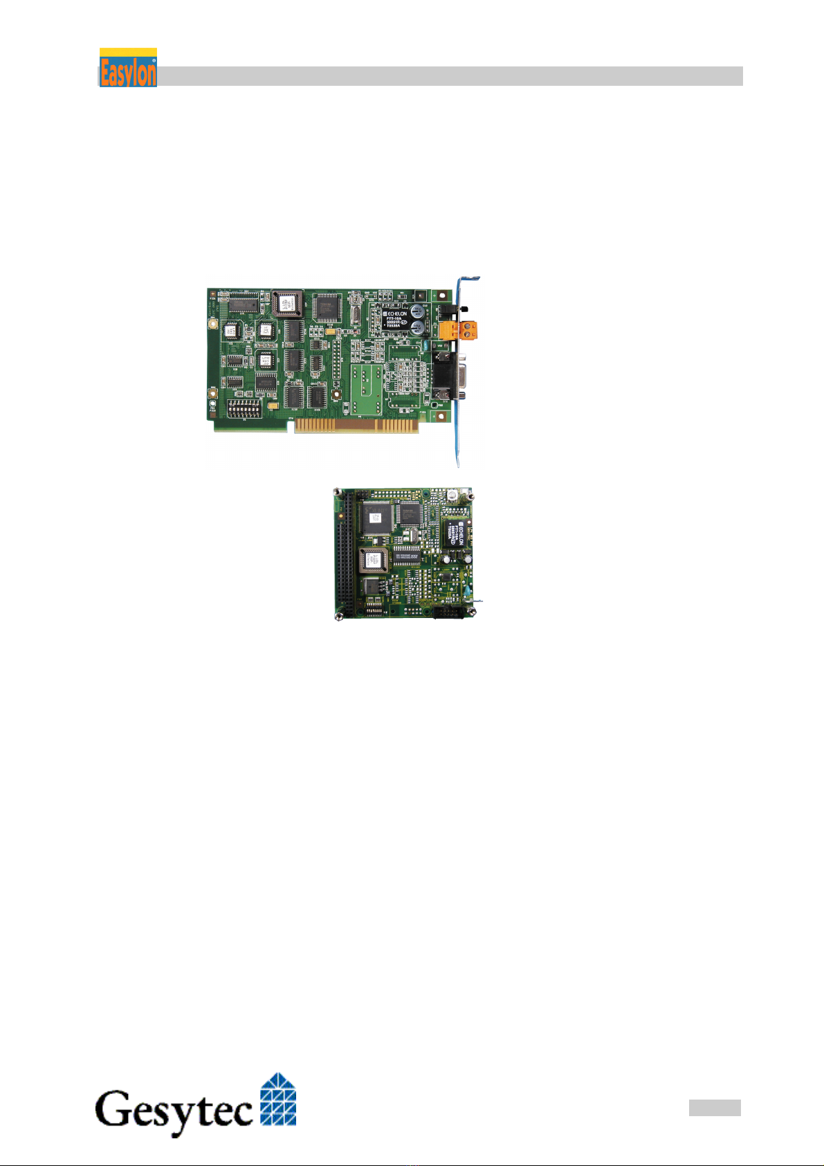
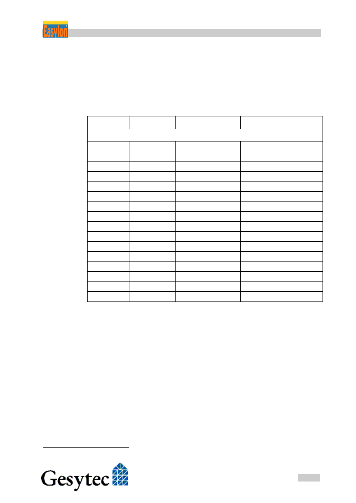
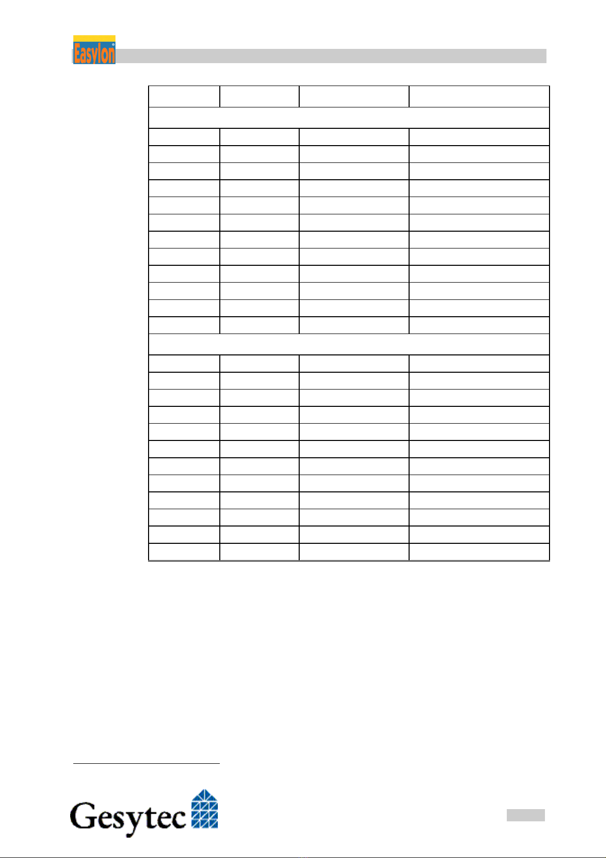
1.1Variants..................................................................................................................7
1.2Scope of Delivery ..................................................................................................9
1.3Overview................................................................................................................9
2Installation........................................................................................................................10
2.1Setting the I/O Addresses ....................................................................................10
2.2Insertion of the Card ............................................................................................11
2.2.1Mounting the Ferrite Core ...................................................................................11
2.3Installation of the Network Driver.......................................................................12
2.3.1Driver for Windows Operating System (WDM Drivers) ....................................12
2.3.1.1Installation ...........................................................................................................12
2.3.1.2Update..................................................................................................................14
2.3.1.3Parameter Setting.................................................................................................14
2.3.1.4De-installation......................................................................................................16
2.3.2Windows 95 / NT Driver .....................................................................................16
2.3.2.1Installation ...........................................................................................................16
2.3.2.2De-installation......................................................................................................17
2.3.3EasyCheck – Test Utility for Windows Drivers ..................................................17
2.3.4Windows and 16 Bit Applications .......................................................................18
2.3.5Windows CE Driver.............................................................................................19
2.3.5.1Installation ...........................................................................................................19
2.3.5.2Use as Dynamic Driver........................................................................................19
2.3.5.3Use as Built In Driver ..........................................................................................20
2.3.6DOS Driver ..........................................................................................................20
2.3.6.1Installation ...........................................................................................................21
2.3.6.2Display of Network Drivers Installed in the Computer.......................................22
3Technical Description ......................................................................................................24
3.1Network Interface ................................................................................................24
3.2ISA Bus Interface.................................................................................................24
3.3Reset Procedure, System Control ........................................................................25
3.4Block Diagram.....................................................................................................25
3.5Connector Pin Assignments.................................................................................27
3.5.1Easylon ISA-Bus Interface ..................................................................................27
3.5.2Easylon PC/104 Interface ....................................................................................28

ISA-Bus Interface User Manual Contents
4
/
44
Archiv/96A0016E01, V3.8, April 2010
3.6Service LED.........................................................................................................29
3.7Connecting External LEDs ..................................................................................29
3.8Technical Specification........................................................................................30
3.8.1General.................................................................................................................30
3.8.2Easylon ISA-Bus Interface ..................................................................................31
3.8.3Easylon PC/104 Interface ....................................................................................31
3.9Electromagnetic Compatibility ............................................................................32
4Programming Instructions..............................................................................................33
4.1LONWORKS Network Node..................................................................................33
4.1.1Interface to the Network ......................................................................................33
4.1.2Node CPU ............................................................................................................33
4.1.2.1Coupling NEURON Chip ‹–› ISA Bus Interface ...................................................34
4.1.2.2Interrupt Function NEURON Chip –› ISA Bus......................................................34
4.1.2.3NEURON Chip Address Map.................................................................................34
4.2Device Status .......................................................................................................35
4.3ISA Bus Interface.................................................................................................37
4.3.1I/O-Address Map .................................................................................................37
4.3.1.1Signal Assignments Control Byte........................................................................38
4.3.1.2Signal Assignments Status Byte ..........................................................................39
4.3.2Reset Procedure ...................................................................................................39
4.4Windows CE – Application Interface..................................................................40
4.4.1CreateFile.............................................................................................................40
4.4.2CloseHandle.........................................................................................................40
4.4.3ReadFile ...............................................................................................................40
4.4.4WriteFile ..............................................................................................................41
4.4.5GetVersion ...........................................................................................................41
4.4.6Watcher................................................................................................................41
4.4.7ReadFile with Timeout ........................................................................................42
5List of Figures...................................................................................................................43
6List of Tables ....................................................................................................................43
7Index..................................................................................................................................44

ISA-Bus Interface User Manual Product Information
5
/
44
Archiv/96A0016E01, V3.8, April 2010
1 Product Information
Two Easylon Interfaces cards are described in this manual:
Easylon ISA-Bus Interface,
plug-in card for short 16 bit
ISA bus slots.
Easylon PC/104 Interface,
ISA bus Interface card in
PC/104 format.
NOTE: In this manual both cards are generally referred to as “Interface cards”. If differ-
ences between the two have to be described, they are explicitly referred to as
“Easylon ISA-Bus Interface” or “Easylon PC/104 Interface”.

ISA-Bus Interface User Manual Product Information
6
/
44
Archiv/96A0016E01, V3.8, April 2010
VCCGND
ST4
IC11
ST2
M1
ST1
Neuron
3150 Chip
GESYTEC
®
®
1 2 3 4 5 6 7 8
OFF
GESYTEC LPC0x
L.LOLPO…
MIP-
Echelon
Figure 1-1 Easylon ISA-Bus In-
terface
(1) Service button
(2) Service LED
(3) Screw-plug terminal (TP/XF and FTT1
variants only)
(4) 9 pin D-type connector
(5) ROM with Echelon‘s MIP/P50 or NSI
(6) Type identifier on rear side (see table
1.1)
(7) DIP switches for setting the card ad-
dress
(8) Connector for Watcher2piggyback
module
1 2 3 4 5 6 7 8
OFF
4
7
8
3
5
1
2
6
1
1 2 3 4 5 6 7 8
OFF
Gesytec
LP4
1
2
3
4
5
7
6
L.LOLPO…
MIP-
Echelon
Figure 1-2 Easylon PC/104 Inter-
face
Type code: LP42.xxx
(1) Service LED
(2) Service button
(3) LON traffic LED (optional)
(4) Shield, MUST be connected!
(5) block terminal for LON bus (pin 1)
(6) DIP switches for setting the card ad-
dress
(7) PC/104-bus connector
(8) Type identifier and serial-# on connect.
Older versions with type code:
LP4.xxx
(1) Service button
(2) Service LED
(3) 10 pin block connector
(4) DIP switches for setting the card ad-
dress
(5) PC/104 connector
(6) Type identifier on rear side (see table
1.1)
(7) Connector for Watcher piggyback
module´
1TPT = transformer coupled twisted pair,
FTT = free topology transceiver
2The Easylon Watcher has been discontinued.

ISA-Bus Interface User Manual Product Information
7
/
44
Archiv/96A0016E01, V3.8, April 2010
1.1 Variants
The following variants of the Easylon Interface cards are currently available and
describe in this manual. There are further, customer specific versions, to which
this manual only partially applies. Each variant is identifiable by a type code
sticker on the rear of the card.
Type Code Order Code Network Interface Variants
Easylon ISA-Bus Interface
LPC.AA P.P10004 FTT MIP/P50
LPC.AB P.P11004 FTT MIP/P50 + Watcher3
LPC.AC P.P10014 FTT NSI
LPC.AD P.P11014 FTT NSI + Watcher
LPC.BA P.P10001 TP/XF-78 MIP/P50
LPC.BB P.P11001 TP/XF-78 MIP/P50 + Watcher
LPC.BC P.P10011 TP/XF-78 NSI
LPC.BD P.P11011 TP/XF-78 NSI + Watcher
LPC.CA P.P10002 TP/XF-1250 MIP/P50
LPC.CB P.P11002 TP/XF-1250 MIP/P50 + Watcher
LPC.CC P.P10012 TP/XF-1250 NSI
LPC.CD P.P11012 TP/XF-1250 NSI + Watcher
LPC.DA P.P10003 E/A-485 MIP/P50
LPC.DB P.P11003 E/A-485 MIP/P50 + Watcher
LPC.DC P.P10013 E/A-485 NSI
LPC.DD P.P11013 E/A-485 NSI + Watcher
Table 1-1 Variants, order-codes and type identifiers for Easylon ISA-Bus
Interface
3The Easylon Watcher has been discontinued.

ISA-Bus Interface User Manual Product Information
8
/
44
Archiv/96A0016E01, V3.8, April 2010
Type Code Order Code Network Interface Variants
Easylon PC/104 Interface
LP42.BA P.P10601 TP/XF-78 MIP/P50
LP42.BC P.P10611 TP/XF-78 NSI
LP42.CA P.P10602 TP/XF-1250 MIP/P50
LP42.CC P.P10612 TP/XF-1250 NSI
LP42.DA P.P10603 RS-485 MIP/P50
LP42.DC P.P10613 RS-485 NSI
LP42.AA P.P10604 FTT10 MIP/P50
LP42.AC P.P10614 FTT10 NSI
LP42.EA P.P10605 Direct Connect MIP/P50
LP42.EC P.P10615 Direct Connect NSI
LP42.FA P.P10606 FTX MIP/P50
LP42.FC P.P10616 FTX NSI
Previous models
LP4.AA P.P10104 FTT MIP/P50
LP4.AB P.P11104 FTT MIP/P50 + Watcher4
LP4.AC P.P10114 FTT NSI
LP4.AD P.P11114 FTT NSI + Watcher
LP4.BA P.P10101 TP/XF-78 MIP/P50
LP4.BB P.P11101 TP/XF-78 MIP/P50 + Watcher
LP4.BC P.P10111 TP/XF-78 NSI
LP4.BD P.P11111 TP/XF-78 NSI + Watcher
LP4.CA P.P10102 TP/XF-1250 MIP/P50
LP4.CB P.P11102 TP/XF-1250 MIP/P50 + Watcher
LP4.CC P.P10112 TP/XF-1250 NSI
LP4.CD P.P11112 TP/XF-1250 NSI + Watcher
Table 1-2 Variants, order-codes and type identifiers for Easylon PC/104
Interface
4The Easylon Watcher has been discontinued.

ISA-Bus Interface User Manual Product Information
9
/
44
Archiv/96A0016E01, V3.8, April 2010
1.2 Scope of Delivery
PC plug-in card with Echelon‘s MIP/P50 or NSI firmware
Installation and Documentation CD including
–network drivers for 32 bit and 64 bit versions of
Windows XP, Vista, 7, Server 2003, Server 2008, Server 2008 R2,
Windows CE, Linux and MS-DOS
–Easylon RNI Software for remote LONWORKS access
–EasyCheck utility for Easylon Interfaces
–WLDV32.DLL
–Documentation in Adobe Acrobat .PDF format
1.3 Overview
The Easylon Interface cards are a cost-effective link between a standard PC or a
PC/104 computer and the LONWORKS network. They provide one interface to the
network. Variants are available for connection via transformer coupled twisted
pair (TP/XF), free topology (FTT) FTX smart, direct connect transceivers and
for EIA-485 serial connection.
Firmware are alternatively MIP/P50 or NSI. While MIP is the cheaper solution
offering more memory NSI will always be needed if LNS is used.
The Easylon ISA-Bus Interface card is provided with a service button and LED.
In the TP/XF and FTT variants, this card is equipped with two connectors, either
of which can be used:
9 pin D-type connector
2 pin screw-plug terminal
Connection to the Easylon PC/104 Interface is made by a 10-pin block connec-
tor. Service button and LED are available on this card as well. Optionally (using
LP42 cards) the signals can as well be used externally.
The PC/104 card is as well available in version for extended temperature range.
Furthermore there are version with a protective coating. These versions comply
with the standard relevant to railway technology.
As an alternative solution to the standard LonTalk adapters described in this do-
cumentation there is a modern solution available with the Easylon Interfaces+.
Especially in more demanding applications these EIA-709.1 based LonWorks
compatible network interfaces offer many advantages. Find more information at
www.gesytec.com.

ISA-Bus Interface User Manual Installation
10
/
44
Archiv/96A0016E01, V3.8, April 2010
2 Installation
Installation of both types of the Easylon Interface cards is carried out in three
steps:
1. Setting the I/O address of the card
2. Insertion of the card
3. Installation of the desired network driver
The Easylon Interface cards are delivered in status "unconfigured". Prior to using
it as a LONWORKS network interface it has to be set "configured". Standard ap-
plications available from the market, such as network management tools, auto-
matically set this status or offer an appropriate command.
For customer specific applications which shall use the Easylon Interface cards
the status setting has to be taken care of. Chapter 4 gives further hints on this
subject. ###
The external interface files (.xif) for the different card variants can be found in
the XIF directory of the installation CD. Table 4-1 references the different file to
the interface card variants.
2.1 Setting the I/O Addresses
Both the Easylon ISA-Bus Interface and the Easylon PC/104 Interface are as-
signed four I/O addresses on the ISA bus of the PC. The base address of this I/O
range is set via DIP switches (cf. Figure 1-1, (7) and Figure 1-2, (6)). Before set-
ting the base address, establish which address range is available on your comput-
er in its current configuration.
From left to right, the switches define address bits 1...8, ad-
dress bits 9 and 10 are set to 00 and can't be set by the user.
When a switch is in its upper position (ON), the address bit
is defined as '1'; in the lower position, the address bit is de-
fined as '0'.
The setting shown in Figure 2.1 corresponds to I/O base
address $340 (11 0100 0000).
1 2 3 4 5 6 7 8
OFF
Figure 2-1 DIP switches

ISA-Bus Interface User Manual Installation
11
/
44
Archiv/96A0016E01, V3.8, April 2010
Examples: Ad-
dress
A9 A8 A7 A6 A5 A4 A3 A2
200 1 0 0 0 0 0 0 0
300 1 1 0 0 0 0 0 0
320 1 1 0 0 1 0 0 0
340 1 1 0 1 0 0 0 0
380 1 1 1 0 0 0 0 0
Table 2-1 Setting the card address
2.2 Insertion of the Card
Prior to inserting the interface cards read the Mounting instructions enclosed in
the delivery. When inserting the Easylon ISA-Bus Interface card or the Easylon
PC/104 card in your computer, please be sure to observe all the computer manu-
facturer's instructions regarding the insertion of additional interface cards.
Insert the Easylon ISA-Bus Interface card into an available 16-bit ISA slot,
Plug the Easylon PC/104 Interface into the PC/104 bus connector.
Connect the interface card with an appropriate cable to the LONWORKS network.
Please refer to Section 3.5, for information regarding the connector pin assign-
ment.
2.2.1 Mounting the Ferrite Core
The Easylon Interface cards are CE certified products and meet the intent of Di-
rective 2004/108 for Electromagnetic Compatibility.
To ensure electromagnetic compatibility in accordance with Directive for opera-
tion of the cards the ferrite core enclosed in the delivery has to be mounted
around the interface cable to the LONWORKS network.
Please put the ferrite core around the interface cable next to
the connector on the board end side (see Figure 2.2). The
distance between the ferrite core and the connector on the
board must not exceed 10 cm. Ensure, if necessary, that it
will stay in place.
Figure 2-2 Mount ferrite core
close to connector

ISA-Bus Interface User Manual Installation
12
/
44
Archiv/96A0016E01, V3.8, April 2010
2.3 Installation of the Network Driver
Drivers for different operating systems are available for the Easylon PCI Inter-
face. Currently these are Windows 2000, XP, Vista and 7 and the Windows
Server OS 2003, 2008 und 2008 R2. The drivers support both, the 32 and the 64
bit version of these operating systems. Furthermore there are drivers for Win-
dows CCE, Linux and MS-Dos. Latest driver versions you can downloadvia the
Easylon Support pages of our web site: www.gesytec.com.
Installation is described in the following sections:
Windows operating systems chapter 2.3.1
Windows 95/NT chapter 2.3.2
16-Bit driver under 32-bit Windows chapter 2.3.4
Windows CE (x86) chapter 2.3.5
DOS Driver chapter 2.3.6
This section also describes in short the diagnosis utility “EasyCheck” which can
be installed separately from CD.
A Linux driver is available in source code from the “Linux” directory on the CD.
This also contains hint s and comments.
The “Driver and Documentation” CD will lead you to the installation of drivers
for different operating systems (OS). However, all setups can as well be started
manually for each OS and the respective interface card directly from the CD.
2.3.1 Driver for Windows Operating System (WDM Drivers)
This section describes installation and setup of the Easylon Interface card drivers
for the Windows operating system from Windows XP onwards.
This setup will install the same driver for all operating systems (Windows Driver
Model).
Finally de-installation of the driver is explained
2.3.1.1 Installation
As these Easylon Interfaces are no Plug-and-Play devices the driver must be in-
stalled manually. The setup is either started by following the guidance given by
the CD or by selecting the directory “Lpclpp” on the Drivers & Documentation
CD and starting the file
FastInst.exe

ISA-Bus Interface User Manual Installation
13
/
44
Archiv/96A0016E01, V3.8, April 2010
The driver will be installed after a few seconds with its standard settings. If you
want to install more than one board, start FastInst.exe the appropriate number of
times and change the resources manually.
The Easylon Interfaces driver will installed with the following standard configu-
ration:
I/O address range: 340-344,
IRQ 5
If the Easylon Interface is to use different resources, these have to be set manual-
ly using the PCs device manager.
Alternative Installation methods
Alternatively you may use the Windows Hardware Assistant for driver installa-
tion. However, this may require stepping through up to 15 dialog boxes.
If you are using this method anyway, please select the setup file „LpcWdm.inf“
and the „Gesytec LPC WDM Driver ISA/PC-104“ driver. One advantage you
will get using this method: resource selection will be made during the installation
procedure.

ISA-Bus Interface User Manual Installation
14
/
44
Archiv/96A0016E01, V3.8, April 2010
2.3.1.2 Update
In case you want to update an existing driver start
FastUpd.exe
from the “Lpclpp” directory on the CD-ROM. A new version will be installed
from CD within a few seconds.
2.3.1.3 Parameter Setting
Certain operating conditions may require special settings for the Easylon Inter-
faces. In the Device Manager select the respective interface board under LON
Adapters and modify the settings.
The „Advanced“ TAB allows setting of individual properties.

ISA-Bus Interface User Manual Installation
15
/
44
Archiv/96A0016E01, V3.8, April 2010
Lon Adapter
You can assign a name „LON1“ ... „LON9“ to the interface board, as some ap-
plications may require.
ATTENTION The name chosen must not be in use by any other driver. The device will not
start if a name is used twice. (Code 10).
Adapter Name
Alternatively a name can be chosen freely (e.g. building 7).
NOTE If names are given in both sections „Lon Adapter“ and „Adapter Name“ only the
name defined under „Lon Adapter“ will be used.
Debug Flag
This field contains a DWORD in hexadecimal notation of different flags for de-
bug purposes. Usually it is set to 0 (= not existing). By setting the single bits cer-
tain debug features can be turned on. At the moment the bits 0, 1 and 2 are used:
Bit 0: LON telegrams at the interface from and to the application are
displayed in the debug output.
Bit 1: LON telegrams at the interface from and to the Neuron Chip are
displayed in the debug output.

ISA-Bus Interface User Manual Installation
16
/
44
Archiv/96A0016E01, V3.8, April 2010
Bit 2: LON telegrams at the interface from and to the Easylon Watcher5
are displayed in the debug output.
Bit 3: CREATE and CLOSE) of the driver are displayed in the debug
output.
NOTE: The Debug Output can be displayed using, for example, the program Debug-
View, available at www.sysinternals.com.
Firmware
The options MIP/NSI or EEBLANK are displayed. These settings are for future
releases and do not have any effects now.
Permitted Power Saving
Usually the Easylon Interface allow the standby mode as well as the hibernate
mode. In certain operating conditions it can lead to errors if the PC, with a LON
application running, changes to hibernate or standby mode. This can be turned
off by selecting “None”.
2.3.1.4 De-installation
De-installation uses the Windows Device Manager. Select the driver „Gesytec
LPCxxx“ under „LON Adapters“ with the right mouse key and choose de-install
2.3.2 Windows 95 / NT Driver
This section describes the driver setup for the Easylon Interface cards for the
Windows 95 and Windows NT operating systems.
The Setup program will automatically install the network driver required by the
computer’s operating system.
Finally, the de-installation procedure of the network driver is explained.
2.3.2.1 Installation
The setup can be started automatically from the user interface of the „Easylon
Drivers & Documentation” CD-ROM.
You can as well start the setup from the CDs file system:
Go to the „Setup” directory and the sub-directory belonging to the Easylon Inter-
face board: „Easylon PC + PC-104 Interface 95+NT“. Start the file
Setup.exe
5The Easylon Watcher has been discontinued.

ISA-Bus Interface User Manual Installation
17
/
44
Archiv/96A0016E01, V3.8, April 2010
During the installation, you will be asked to specify the path for the installation
of the utilities and demo sources. Optionally, you can accept the suggested path
or may specify your own.
At the end of the setup, the following dialogue will appear:
Here, you can adjust the I/O address of the Easylon Interface card and the allo-
cated interrupt (IRQ).
NOTE: This driver does not support multiple Interfaces in one computer!
2.3.2.2 De-installation
De-installation of the drivers is done via the system control software. For this,
first choose the item "Easylon ISA-Bus Interface" and then click "Insert/Delete".
After the de-installation, the system has to be restarted.
2.3.3 EasyCheck – Test Utility for Windows Drivers
In addition to the drivers, the test utility “EasyCheck” can be installed in the re-
spective program directory (default: : \Easylon\Lpx ). The program checks inter-
face and software environment and displays information, from which can be
concluded on the reasons for problems in connection with the interface.
EasyCheck runs an analysis of the system’s software. It will open the selected in-
terface, check the driver version and display it. By sending a “query status”
command the communication with the hardware is tested. Using the “read mem-
ory” command the utility will show if the device is running MIP or NSI firm-
ware. Properly installed Easylon Interfaces will send a corresponding answer.

ISA-Bus Interface User Manual Installation
18
/
44
Archiv/96A0016E01, V3.8, April 2010
2.3.4 Windows and 16 Bit Applications
The Windows driver for the 32 bit Windows versions also provides a 16 bit in-
terface. (Unfortunately Microsoft does not support this in the 64 bit versions.) To
use it, the following entry has to be made in the file „config.nt“, usually found in
the windows\system32 directory:
Device=%SystemRoot%\system32\ lpxdos.exe –Llpcwdm340
A more specific definition of the 32 bit LON device used is made by optional pa-
rameter:
/Lname
name =
lvxwdm5-0-Mip0 for device LVX wth PCIe-bus number 5,
PCI device number 0 and instance 0
lvuwdm1-2-Mip0 for device LVU at USB host controller 1
and with port number 2 at USB root hub
lvpwdm0-14-Mip0 for device LVP with PCI-Bus number 0,
PCI device number 14 and Instance 0
lpcwdm340 für Device LPC mit I/Oport Adresse 340
lppwdm0-14 für Device LPP mit PCI-Bus-Nummer 0
und PCI Device-Nummer 14
lonusb1-2 für Device LONUSB an USB Hostcontrol-
ler 1 und mit der Portnummer 2 am USB-
Root-Hub.
lpcdrv für Device EasyLPC mit der Nummer 1
lpp1 für Device EasyLPP mit der Nummer 1
Note: Two subsequent “l” characters have to be entered, one indicating the parameter -
L, the second as first character of the name: –Llxxxx
A more specific definition of the 16 bit LON device used is made by optional pa-
rameter:
/Dn with n = 1...9 for LON1 to LON9
Without this parameter, the interface will be assigned the first unused name start-
ing with “LON1”.

ISA-Bus Interface User Manual Installation
19
/
44
Archiv/96A0016E01, V3.8, April 2010
2.3.5 Windows CE Driver
Driver and .reg file for Windows CE can be found in the „Windows CE“ direc-
tory of the CD.
The Windows CE driver has been designed for x86 processors. There are ver-
sions for Windows CE 3.0 and 4.2, 5.0, 6.0. They can be installed in two ways:
1. CE devices with static RAM:
Copy the lpcdrv.dll into the \Windows directory
2. else:
Create a new image with the driver included in your lpcdrv.bib file.
This is for advanced users only, who want to create a custom kernel!
In both cases you have to create the registry entries with your desired IRQ and
I/O settings as described below. These settings, of course, depend on your sys-
tem resources.
2.3.5.1 Installation
The driver will use the I/O base address as well as the interrupt of a LON device
found in the registry. To use an Easylon Interface card as device named LON1
with the base address 0x340 and interrupt IRQ 10 (=0x0A hex) you have to add
following in the file „Lpcdrv.reg“:
[HKEY_LOCAL_MACHINE\Gesytec\Lpcdrv\LON1]
"IoBase" = dword:0340
"Irq" = dword:a
The .reg file is provided in the Windows CE driver directory.
2.3.5.2 Use as Dynamic Driver
RegisterDevice
This will register the driver and make it available as LON device. This device is
then available as LONx and can be opened by the function CreateFile(). (cf.
chapter 4.3)
Syntax:
hDev = RegisterDevice (L"LON", dwIndex, TEXT("lpcdrv.dll"),
dwIndex);
Parameter Type Description
dwIndex DWORD LON device number
(1 = LON1:, 2 = LON2: etc.)

ISA-Bus Interface User Manual Installation
20
/
44
Archiv/96A0016E01, V3.8, April 2010
Return value Type Description
hdev HANDLE valid device handle or NULL, if driver has al-
ready been registered.
DeregisterDevice
This will remove the registration of the driver. Before you remove the registra-
tion you must close the device!
Syntax:
DeregisterDevice(hDev);
Parameter Type Description
hdev HANDLE Device handle.
2.3.5.3 Use as Built In Driver
If you want to register the driver as LON1 during startup of Windows CE you
have to make the following entries in the file “Lpcdrv.reg”:
[HKEY_LOCAL_MACHINE\Drivers\BuiltIn\lpcdrv]
"Prefix"="LON"
"Dll"="lpcdrv.dll"
"Order"=dword:0
"DeviceType"=dword:0
"LON"=dword:1
NOTE: In this case the functions RegisterDevice() and DeregisterDevice() must not be
used by any application!
NOTE: It is allowed to open a device multiple times, for example one application can
use the NEURON Chip and another application can use the Watcher of an Easylon
Interface.
A main functionality of Windows CE driver support is to be able to register a
driver several times. This driver will handle several devices in parallel. However,
this release of the Gesytec LonWorks network driver for Windows CE does not
support this mechanism! As a workaround you have to copy and rename the
driver, e.g. lpcdrv1.dll, lpcdrv2.dll. Then each of these drivers can be used as a
single driver for each LON device.
2.3.6 DOS Driver
The network driver for MS-DOS supplied with the Easylon Interface card has
been designed in accordance with the specifications by Echelon Corporation. For
information on the network driver interface which is required to develop ap-
plications, please refer to the "LONWORKS Host Application Programmer's
Guide" from Echelon.
This manual suits for next models
25
Table of contents
Other Gesytec Recording Equipment manuals