Albalá Ingenieros ATG3000C01 User manual

ATG3000C01
AUDIO TONE GENERATOR
Version 1.0
Albalá Ingenieros, S.A.
Medea, 4 - 28037 Madrid - Spain
21 December 2016 - © Albalá Ingenieros S.A. - All rights reserved

ATG3000C01

ATG3000C01
AUDIO TONE GENERATOR
Version 1.0
1. DESCRIPTION ...................................................................................................................... 5
1.1. The ATG3000C01 ............................................................................................................................ 5
1.2. Features ............................................................................................................................................. 5
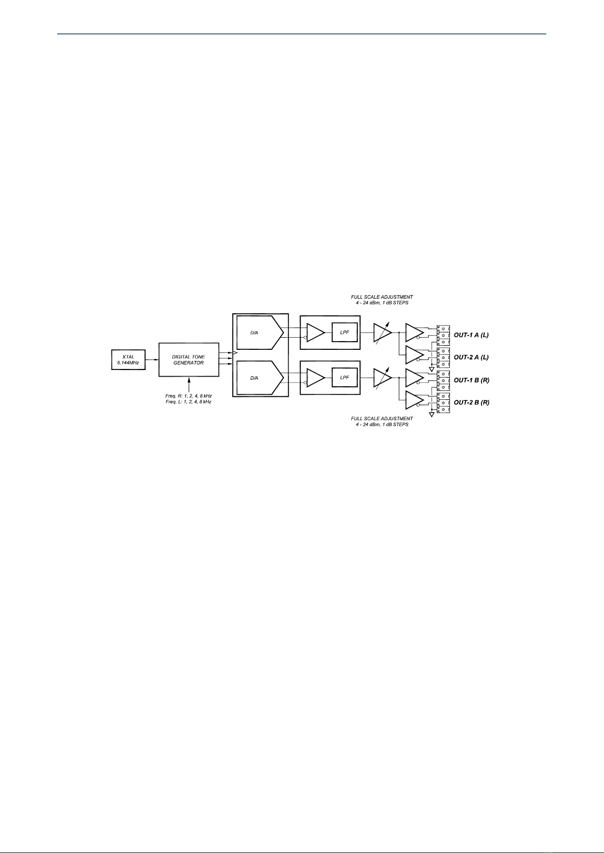
1.3. Block diagram .................................................................................................................................. 6
2. SPECIFICATIONS ................................................................................................................. 7
3. INSTALLATION .................................................................................................................... 9
3.1. Initial inspection ............................................................................................................................. 9
3.2. Safety instructions ......................................................................................................................... 9
3.3. Environmental considerations ................................................................................................ 10
3.4. Power considerations ................................................................................................................. 10
3.5. Module configuration ................................................................................................................ 10
3.5.1. Selection of the tone frequency ..................................................................................... 10
3.5.2. Level selection ...................................................................................................................... 11
3.6. Installing the module in the mounting frame ................................................................... 11
3.7. Interconnection ............................................................................................................................ 13
3.7.1. Analog audio connections ............................................................................................... 13
4. OPERATION ...................................................................................................................... 15
4.1. Front panel description .............................................................................................................. 15
4.2. Module remote control and supervision ............................................................................. 16
5. GLOSSARY ........................................................................................................................ 17
6. REGULATIONS .................................................................................................................. 19
7. VERSIONS ......................................................................................................................... 21

ATG3000C01

Albalá Ingenieros | Manual ATG3000C01
1. DESCRIPTION
1.1. The ATG3000C01
The ATG3000C01 module is a two-channel analog audio tone generator. The frequency
of the tones can be selected from the following values: 1, 2, 4 or 8kHz. The output level
is adjustable from 3 to 24dBu in 1dB steps. Both the frequency and the level can be set
independently for each channel.
The tones are generated in the digital domain using direct digital synthesis and are then
converted to analog using high linearity converters, guaranteeing high stability and low
harmonic content.
The ATG3000C01 is a TL3000 terminal line module and can be housed in a three rack
unit (3 RU) UR3000 mounting frame or a 1 RU UR3100 mounting frame.
1.2. Features
• Analog audio signal generator.
• Generates an audio tone on two channels.
• Allows selection of tone frequencies between 1, 2, 4 and 8kHz for each channel.
• Allows selection of tone amplitude from 4 to 24dBu in 1dB steps for each channel.
• Electronically balanced analog audio outputs.
•One UR3000 mounting frame can house up to 12 ATG3000C01 modules. If power
supply redundancy is required and FA3000 or FA3001 modules are used then only 10
modules can be housed in the mounting frame. If PSU3300 or PSU3301 modules are
used for this purpose then up to 12 modules can be installed.
• One UR3100 mounting frame can house up to three ATG3000C01 modules.
• Low power.
5

Albalá Ingenieros | Manual ATG3000C01
1.3. Block diagram
6

Albalá Ingenieros | Manual ATG3000C01
2. SPECIFICATIONS
Analog audio signal output
Connector Plug-in terminal,
3.81mm pitch
Impedance 73Ω ± 1 %
Type Active balanced
Number of outputs 2 per channel, 2 channels
Difference between a 600Ω loaded output and an unloaded output 1 dB
Maximum output level 24 dBu
Output offset voltage <30 mV
Digital to analog converter
Number of bits 24
Full scale level 4 to 24dBu, 1dB steps
Pass-band ripple + 0.1 / - 0.3dB from 20Hz to 20 kHz
Signal to Noise ratio (S/N):
Unweighted >104dB measured with a
1kHz, - 60dBFS tone,
20Hz to 20kHz
Harmonic distortion plus noise (THD+N) <- 95dB measured with a
1kHz, 0dBFS tone,
20Hz a 20kHz,
output loaded with 600 Ω
Crosstalk between channels <- 95dB measured at 1 kHz
General
Maximum power supply current + 250 / - 210 mA
Operating temperature range 0 .. 50 °C
Approximate weight 300 g
7

Albalá Ingenieros | Manual ATG3000C01
ATG3000C01
8

Albalá Ingenieros | Manual ATG3000C01
3. INSTALLATION
THE ATG3000C01 MODULE CONTAINS ELECTRONIC DEVICES SENSITIVE TO
ELECTROSTATIC DISCHARGE. Always use antistatic bags clearly identified
with a high degree of shielding for storage and transportation.
The ATG3000C01 module is composed of two parts: one ATG3000P01 main board and
one ATG3000P02 rear board. Both parts must be installed in a UR3000 or UR3100
mounting frame following the instructions in the corresponding section of this chapter.
3.1. Initial inspection
Verify that the package has been properly handled during transport. After opening the
packaging, check that one ATG3000P01 main board and one ATG3000P02 rear board are
inside.
You must notify your Albalá Ingenieros distributor or dealer of any damage or defects
observed.
Follow the instructions in this manual to install this module in the mounting frame.
3.2. Safety instructions
•This equipment must be connected to a mains outlet with a protective
earth connection. Never use extension cords that do not have protective
earthing connection. The lack of an effective electrical connection between
the ground pin in the mains input connector of the equipment and the
protective earth of the electrical power distribution can cause serious harm.
•All modules of the Albalá Ingenieros TL3000 terminal line can be
hot-plugged or unplugged without suffering any damage or affecting the
processes that are currently taking place in other modules in the same
mounting frame. When a module is installed in an empty bay of a mounting
frame, it is necessary to mount the rear board that is part of that module.
Prior to installing this board, the mounting frame must be disconnected
from the power supply network. This is required because in addition to the
risk of electrocution for the person handling the device it is possible that a
high instantaneous current coming from the power supply could damage
the connectors and components of the mounting frame and/or the rear
board.
9

Albalá Ingenieros | Manual ATG3000C01
•The ATG3000C01 module and the mounting frame should always be
installed, maintained, operated and removed by personnel with sufficient
technical qualifications. The equipment should never be placed in damp
areas, near splashing liquid, or in explosive or corrosive atmospheres.
Neither modules nor mounting frames can be used in applications that
could endanger human life.
3.3. Environmental considerations
This symbol indicates that this equipment must be deposited at a collection
point for proper waste treatment once it has reached the end of its useful
life.
3.4. Power considerations
The UR3000 and UR3100 mounting frames can house as many ATG3000C01 modules as
will fit in them.
3.5. Module configuration
In addition to mechanical installation of the module into a mounting frame, several
program jumpers must be set to select the output signal levels. The tone frequencies are
set using selector microswitches.
The ATG3000C01 contains microswitches and program jumpers that should be set
before installation of the module into a mounting frame. These devices set:
- Selection of the tone frequency.
- Tone level adjustment.
3.5.1. Selection of the tone frequency
Switches 1 and 2 of S1 are used to set the frequency of the left channel according to
the following table.
L channel FREQUENCY S1
(kHz) 1 2
1 OFF OFF
2 ON OFF
4 OFF ON
8 ON ON
10

Albalá Ingenieros | Manual ATG3000C01
Switches 3 and 4 of S1 are used to set the frequency of the right channel according to
the following table.
L channel FREQUENCY S1
(kHz) 3 4
1 OFF OFF
2 ON OFF
4 OFF ON
8 ON ON
3.5.2. Level selection
Selection of the level is set using program jumpers J2 and J5 along with switch 5 of S1
as described in the following:
-Use switch 5 of S1 to the set the output level range. When set to ON the
adjustment runs from +16 to +24dBu, and when set to OFF the adjustment runs
from +4 to +16dBu.
-Set jumper J2 to select the desired level for the right channel. The position labeled
''22dBu'' will output a 22dBu level when switch 5 of S1 is set to ''ON'' and will
output a level of 10dBu when switch 5 of S1 is set to ''OFF''.
-Set jumper J5 to select the desired level for the left channel. The position labeled
''22dBu'' will output a 22dBu level when switch 5 of S1 is set to ''ON'' and will
output a level of 10dBu when switch 5 of S1 is set to ''OFF''.
3.6. Installing the module in the mounting frame
The steps needed to install the ATG3000C01 module with the rear board in the
mounting frame are:
1 - Disconnect all power cords from the power supplies of the mounting frame.
2 - Remove the blank panels covering the front and rear of the empty bays chosen for
installing the ATG3000C01 in the mounting frame.
3 - Install the ATG3000P02 rear board ensuring that its 12-pin connectors are properly
aligned with the mounting frame´s mating connectors. Check that the orientation of
the board is correct by looking at the placement of the text printed on it according to
the illustration below.
4 - Attach the rear board to the mounting frame with two M3 metric screws and tighten.
11

Albalá Ingenieros | Manual ATG3000C01
Details for installation of the module in 3 RU mounting frames
Details for installation of the module in 1 RU mounting frames
5 - Verify that the main board is configured according to the user requirements. The
configuration process is detailed later in the INSTALLATION section of this manual.
6 - Insert the ATG3000P01 board (main board of the ATG3000C01 module) into the front
of the mounting frame. The edges of the card slide into two plastic guides inside the
mounting frame.
7 - Affix the main board to the mounting frame using the two screws included on the
front panel.
After these steps, the module is ready to be connected to other equipment.
12

Albalá Ingenieros | Manual ATG3000C01
3.7. Interconnection
The following figure shows the ATG3000C01 module rear board connector layout.
Rear view of the ATG3000C01
The ATG3000C01 module generates two independent audio tone signals (OUTA(L) and
OUTB(R)) and distributes them to two outputs (OUTPUT 1 and OUTPUT 2).
The rear interconnection board is not designed to withstand mechanical stress. The
wiring must be fastened properly to the frame where the mounting frame is housed to
prevent the rear board from supporting the weight of the cables.
3.7.1. Analog audio connections
The analog audio outputs are balanced, use 3.81mm pitch terminal block connectors
and their characteristic impedance is 73Ω.
For analog audio connections two-wire shielded cable is preferred. The GND terminal
allows connection of the cable shield.
13

Albalá Ingenieros | Manual ATG3000C01
ATG3000C01
14

Albalá Ingenieros | Manual ATG3000C01
4. OPERATION
This section describes the significance of the front panel indicators of the ATG3000C01
module and their remote control and monitoring ability.
4.1. Front panel description
The appearance of the front panel and the elements it contains are shown in the
following illustration.
Front panel of the ATG3000C01
The front panel doesn't contain any indicator.
15

Albalá Ingenieros | Manual ATG3000C01
4.2. Module remote control and supervision
The ATG3000C01 CANNOT be remotely controlled or supervised.
16

Albalá Ingenieros | Manual ATG3000C01
5. GLOSSARY
dB
Logarithmic measurement to express ratios of power.
dBu
Logarithmic measurement referring to 0.7746V which is the voltage that dissipates
1mW (0dBm) of power when applied to a 600 ohm resistor.
17

Albalá Ingenieros | Manual ATG3000C01
ATG3000C01
18

Albalá Ingenieros | Manual ATG3000C01
6. REGULATIONS
19

Albalá Ingenieros | Manual ATG3000C01
ATG3000C01
20
Table of contents
Other Albalá Ingenieros Recording Equipment manuals
Popular Recording Equipment manuals by other brands

Rockwell Automation
Rockwell Automation AB Quality Allen-Bradley MicroLogix... user manual

Altinex
Altinex MULTI-TASKER MT103-127 user guide

METRObility Optical Systems
METRObility Optical Systems twister T1 Installation & user guide

Digital Equipment
Digital Equipment Pro-face GP2000 Series user manual

Korg
Korg Pandora Stomp owner's manual

Resonessence
Resonessence CONCERO user guide