8
Site Preparation
Floor/Walls
Prior to installing the Parker bath, the floor and
walls of the required area must be finished.
The floor should be made of a slip resistant ma-
terial and must be water sealed.
When using a floor drain, the floor must have a
maximum slope of 1:50 towards floor drainage
with a capacity exceeding the minimum drain-
age capacity.
A floor drain is required in case the bath door is
unintentionally opened or the bath is being
overfilled.
The doorway shall not have a threshold but if
necessary, it should be made of depressive rub-
ber material, to facilitate the use of a mobile aid.
The Parker bath must be installed more than
250 mm (10”) from any fixed object, to avoid
having body parts jammed. Also make sure
there is 50 mm (2”) between the fully opened
Parker bath door and the ceiling.
IfaceilingliftwillbeusedtogetherwithParker
bath, make sure to install the ceiling rails cen-
tred over the bath or the bath centred under the
rails, whichever gets installed first.
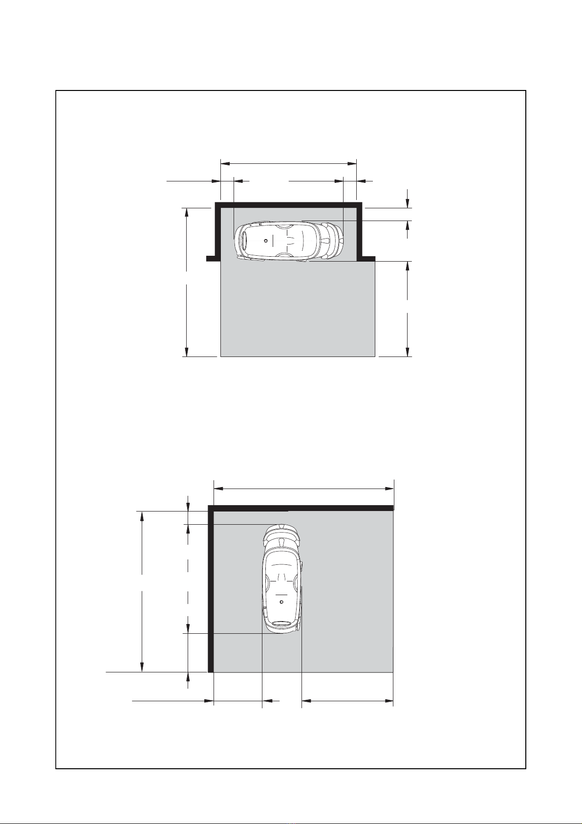
Space requirements around the
bath
Parker bath should always be installed accord-
ingto recommended spacerequirements, this to
provide optimal working conditions for person-
nel and resident. (Figure 1.)
•.
Front against wall Back against wall
The slope should not exceed 1:50.
The shaded areas are mainly designated for water
drain/supply and electrical connections/outlets
NOTE
Space for furniture and other personal
items are not included in these measure-
ments.
NOTE
These dimensions are approximate and
unless otherwise stated, should be
treated as minimum requirements.