Geutebruck G-ST 6000+ G2 User manual

G-ST 6000+ G2
Installation manual

Introduction
The information in this document can be changed without prior notice.
Without the express written consent of GEUTEBRÜCK, no part of
these documents may be reproduced or transferred, either mechani-
cally or electronically, for any use.
© 2020 by GEUTEBRÜCK All rights reserved.
These operating instructions represent the current technological state
of our devices. Errors and omissions excepted.
These operating instructions provide you with all the necessary infor-
mation to use the G-ST 6000+ G2 safely and properly.
Please read and observe these operating instructions so that errors
and danger can be avoided.
The operating instructions are valid for the G-ST 6000+ G2. The
operating instructions are only valid when the device corresponds to
the version described herein.
These instructions contain all specifications that are required for
transport, assembly and commissioning of the devices.
Please read these instructions carefully before initial operation to en-
sure safe use of the devices.
If malfunctions or repair needs should occur, please contact our quali-
fied personnel.
All maintenance and repair work is to be performed by qualified per-
sonnel.
If maintenance or repair work is neglected or performed improperly,
our guarantee becomes null and void.

Introduction
2 V 1.0
Contents
Introduction ...................................................................................... 1
General notes and safety ................................................................. 3
Intended use ............................................................................................... 3
Description and definition of signs .............................................................. 3
General safety instructions ......................................................................... 4
Transportation, storage, initial commissioning ........................................... 5
Scope of delivery ........................................................................................ 5
Device description ........................................................................... 6
Overview of G-ST 6000+ G2 ...................................................................... 6
Device view................................................................................................. 7
Front view .......................................................................................................... 7
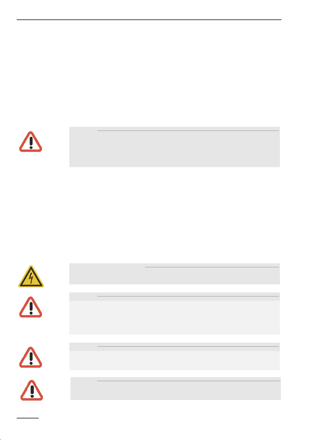
Rear view G-ST 6000+ G2 ................................................................................ 8
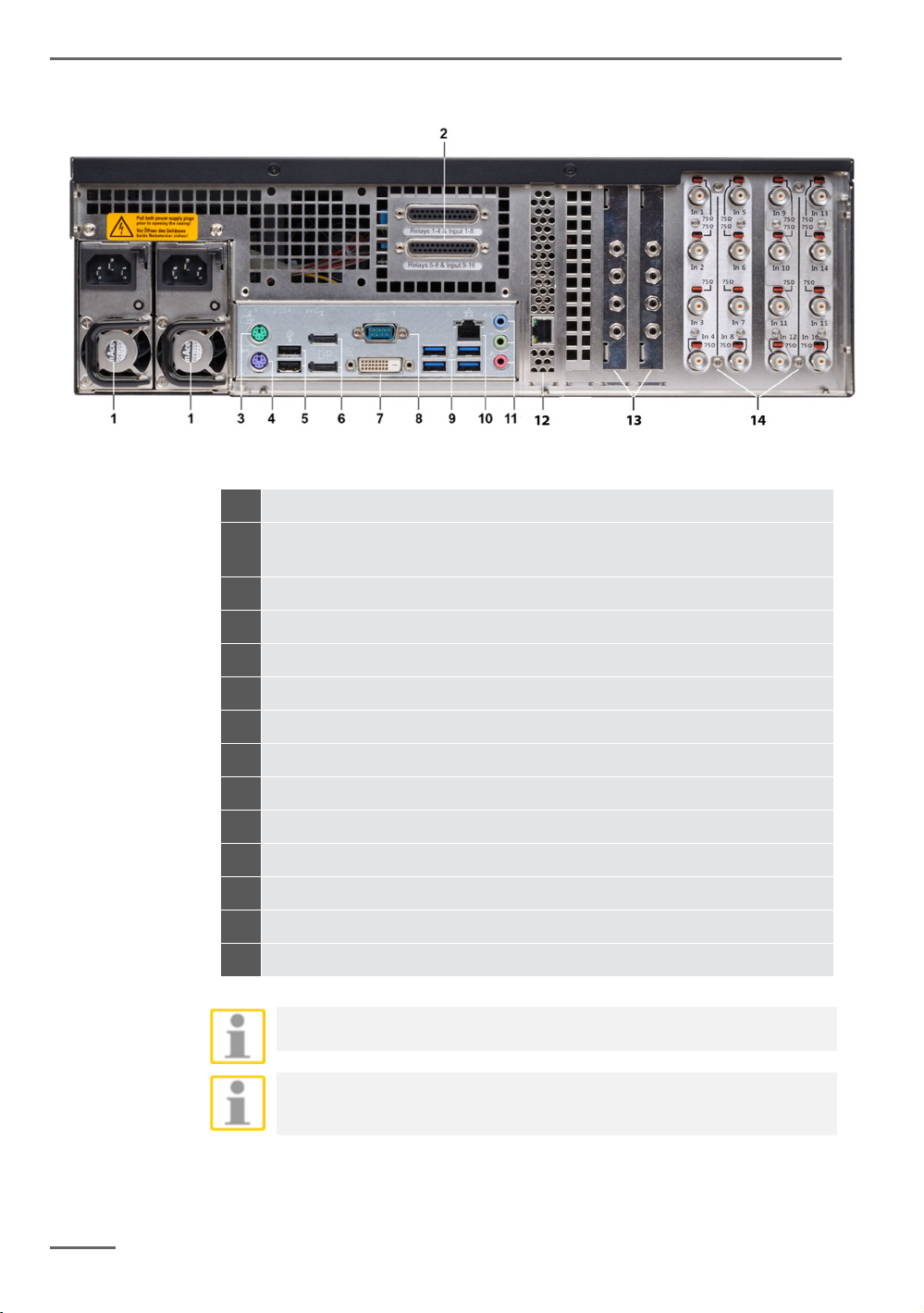
Hard Disk Drive Carrier ...................................................................................... 9
Removing the disk drive carrier ....................................................................... 10
Changing a Redundant Power Supply ............................................................ 11
Installation and commissioning .................................................... 12
Requirements ........................................................................................... 12
Checking the conditions ................................................................................... 12
Tool for commissioning .................................................................................... 12
Preparations .................................................................................................... 13
Instructions on installation of in-house PC cards and external devices ........... 13
Connecting devices .................................................................................. 14
Turning on the device ............................................................................... 14
Integrating the device into the network ..................................................... 16
Working with the G-ST 6000+ G2 .................................................... 17
Overview ................................................................................................... 17
Using the online documentation ............................................................... 19
Managing I/O contacts .............................................................................. 20
Assigning contacts ........................................................................................... 20
Adding I/O contacts in G-Set ........................................................................... 21
Using other connections ........................................................................... 23
Analog Video Connections (optional) ............................................................... 23
Connecting printers .......................................................................................... 23
Additional external connections ....................................................................... 24
Turning off the device ............................................................................... 25
Resetting the system to factory settings ..................................... 26
Appendix Technical Data ............................................................... 26

General notes and safety
3
V 1.0
General notes and safety
Intended use
The G-ST 6000+ G2 is a high performance, digital video management system
based on modern processor architectures.
The G-ST 6000+ G2 supports direct recording and playback of network cameras.
The recording rate depends on the type of network camera.
Standard and megapixel cameras can be recorded in all resolutions supported by
the camera and are displayed in the corresponding format.
Description and definition of signs
Symbols and pictograms are used in these instructions, with whose meaning you
should familiarize yourself. These symbols will help you to understand the infor-
mation in these instructions more quickly and point out danger or particularly im-
portant information.
Warning!
Danger signs. In order to avoid physical injury and material damage, these alert you
to danger as well as instructions that must be followed and things that are prohibited.
Warning of electric energy!
Danger to life! Please note that work on electric equipment may only be performed
by qualified electricians.
Warning!
Warning sign: the device can start up without warning.
Definition of terms
User, operator: Person who has been authorized to operate the device by the
operating company. The user must be instructed by the operating company with
regards to safe use with the device.
Operating company: Responsible for safe installation, regular maintenance
and cleaning of the device.
Qualified personnel: Trained specialists, authorized by the operating company
or GEUTEBRÜCK who is familiar with the devices and with the technology.
Qualified personnel must be trained and capable of performing maintenance
and repair work on the device.

General notes and safety
4 V 1.0
General safety instructions
When using the devices or performing maintenance on them, the following safety in-
structions are to be observed to protect the operator, the service technician and the
device:
During design and construction of the devices, the acknowledged state of the art
as well as the acknowledged applicable standards and directives have been
taken into account and implemented.
Additionally, the devices have been designed and developed so that the danger
that occurs during intended use has been eliminated to the greatest possible ex-
tent.
Nonetheless, we are obligated to describe these safety instructions so that the resid-
ual dangers can be eliminated.
Warning!
When electric machines are used, fundamental safety precautions must be observed
to eliminate the risk of fire, electric shock and injury to persons. For this reason,
please read these operating instructions before starting your work. Store these in-
structions in a place where the qualified personnel and user can access them quickly
and easily.
When operating the device, the locally applicable laws, regulations and standards
must be observed. In the interest of safety, the operating company and supervisors
are responsible for compliance.
Whenever performing any kind of work, check for any possible damage. All parts
must be mounted correctly and all conditions fulfilled to ensure proper functioning.
If the device is damaged in any way, it may no longer be used. Ensure that the de-
vices are repaired properly. Mark the defect clearly and pull the power plug so that
no accidents or damage can occur before the device is repaired.
Do not use the power line for uses for which it is not intended. Protect the cable from
heat, oil and sharp edges.
In dangerous situations or technical malfunctions, disconnect the device from the
power supply immediately.
Warning of electric energy!
In case of damage, the device may no longer be used. Disconnect the device from
the power supply!
Warning!
For all repair and maintenance work, the device must be disconnected from the
power supply. Work on electrical equipment may only be performed by qualified
electricians.
Only original parts may be used. Otherwise, the user is subject to danger of acci-
dent.
Warning!
The use of parts and related accessories other than those specified in these operat-
ing instructions can lead to injury. Only use replacement parts approved by the man-
ufacturer!
Caution!
Risk of explosion if mainboard battery is replaced by an incorrect type.
Dispose of batteries in accordance with local laws and regulations!

General notes and safety
5
V 1.0
Transportation, storage, initial commissioning
Transportation and storage
The device is shipped from the factory in a shipping box with a special cushion pack-
ing. This protects the device from damage during transportation. Whenever possible,
use the original device packaging.
Transportation and storage conditions
Temperature range: -25°C to +55°C
Relative humidity: 10% to 90% (without condensation)
Installation instructions and initial commissioning
The devices may only be installed by qualified personnel who are familiar with
the devices.
The device may only be commissioned after it has been ensured that all applica-
ble safety requirements have been fulfilled.
Scope of delivery
Ensure that the following items are included in the delivery:
G-ST 6000+ G2
Manual
Installations/recovery DVD
Power cord
Manufacturer's driver CD

Device description
6 V 1.0
Device description
Overview of G-ST 6000+ G2
Recommended uses and applications
The G-ST 6000+ G2 is a high
availability, redundant system
platform for use in large
branches.
Due to the flexible expandability
with a wide range of software
options, such as video content
analysis or interfaces to third-party systems, it is perfectly suited for all types of
video security applications as well as automatic process visualization (value im-
aging) in logistics supply chains.
Product features
Professional server video security solution for medium-sized installations to
networked installations.
Redundant power supply unit, integrated RAID system (8 hard drive slots).
High-End Video Engine G-Core (optional).
Excellent image processing power through the use of GPU acceleration and
64-bit architecture.
Windows 10 IoT Enterprise.
Connection of up to 80 IP cameras.
3 x G-Core/ViewConnect (8.34010) included, 10 maximum (optional).
Supported image database size of 80 TB (70 TB for RAID-5).
Fulfillment of the most stringent data-privacy requirements:
Encrypted transmission, privacy masking, manipulation-proof database ar-
chitecture, watermark, comprehensive access rights definitions (optional).
Configurable analog kits for the additional connection of 8 or 16 analog
cameras.

Device description
7
V 1.0
Device view
Front view
Figure 1: Front view
Figure 2: Front view without cover
1 LED (white) Power
2 LED (red) Error
3 LED (white) Record HDD
4 USB (2x)
5 Action pushbutton (finger actuated)
6 Reset pushbutton (pin actuated)
7 Power pushbutton (pin actuated)
8 Alarm Reset pushbutton (pin actuated)
9 LED (yellow) HDD in use
10 LED (white) Fan error
11 LED (red) Power supply error
12 SSD changeable (2x)
13 S-ATA Hard disk drive bay equipped with carrier (8x)

Device description
8
V 1.0
Rear view G-ST 6000+ G2
Figure 3: Rear view G-ST 6000+ G2
1 Mains Power supply
2 Control inputs for connecting external contacts for the event-based
image recording/relay outputs
3 Connection for PS/2 PC keyboard (6-pin mini-DIN socket)
4 Connection for PS/2 PC mouse (6-pin mini-DIN socket)
5 USB 2.0 interfaces (2x)
6 Display Port (2x) for connecting a PC monitor
7 DVI-D graphics output for connecting a PC monitor
8 Serial RS-232 interface COM1 (9-pin Sub-D connector)
9 2 x USB 3.1, 2 x USB 3.0
10 Network connection (Ethernet 10 /100 / 1000 Base/T - RJ45)
11 Audio connections
12 RAID controller remote management port 10/100 MBit/s
13 AnalogKit Audio Line In optional
14 FBAS inputs on AnalogKit optional
When using an analog monitor you need a DisplayPort to VGA adapter
(Art. No.: 5.39401).
The position of the connections may vary!
Please check the accompanying mainboard manual if the configuration is
different.

Device description
9
V 1.0
Hard Disk Drive Carrier
1 Power LED
continuous green light when disk in and power on
2 Access LED
S-ATA: no light in idle mode, blinking blue light when access
3 Failure/ Rebuiling LED
Failure: continuous red light
Rebuilding: blinking red light when the specific disk is build in a degraded
array
4 Handle lock
pressing it to the left unlocks the drive from the bay
5 Disk-ID
consecutive numbering according to the numeration in the RAID Controller
storage management

Device description
10
V 1.0
Removing the disk drive carrier
Disk drives could be removed when system is off, but also when system is running
(Hot Plug). This only should be done in case of a disk failure. Do not pull out disks
during system is running, when there is no disk failure. Pulling out properly working
disk during system is up may cause data loss.
Press the handle lock.
Pull the carrier handle in your direction.
Pull out the carrier from the chassis.
To put the disk drive carrier back into the system push it in the drive bay as far
as possible.Then push the carrierhandle to lock the carrier.

Device description
11
V 1.0
Changing a Redundant Power Supply
A power supply could be removed when system is off, but also when system is run-
ning (Hot Plug). This only should be done in case of a power supply failure.
Remove the power cord from the back of the power supply.
Press the locking lever downwards.
Pull firmly on the power supply handle to remove it.
Insert the plug-in module into the system. Push the module as far as possible
into the enclosure. Close the locking lever to arrest the plug-in module.

Installation and commissioning
12 V 1.0
Installation and commissioning
Requirements
Checking the conditions
Before you integrate your G-ST 6000+ G2 into an existing network, you must en-
sure that the following conditions are met:
There is a functioning network with TCP/IP protocol (100/1000 Mbit Ethernet).
For other networks, the successful integration of G-ST must first be demon-
strated.
For commissioning, a network administrator is required on site who can inter-
vene promptly when problems with the network arise.
The responsible network administrator must provide a free IP address, in some
cases with subnet mask and default gateway, for every G-ST and for each con-
figuration and playback PC. In addition, a free IP address is required per net-
work segment. This additional IP address will be used for test setups during
commissioning and must remain available after completion of work.
With the help of the PING diagnostic tool, which is normally executed as a con-
sole command, functional communication between the G-ST and the configura-
tion or playback PCs must be confirmed. You can also demonstrate functional
name mapping using PING. You start the command window using right klick on
Start left klick on Command promp enter PING + IP adress.
Tool for commissioning
Ensure that before commissioning, all accessories needed for installation are availa-
ble and connect these accessories.
If configuration and operation of the system is to be performed directly on the
G-ST, you need the following equipment:
S-VGA monitor (min. resolution of 1024 x 768 pixels, 17-inch recommended)
USB keyboard and USB mouse.
Connect the mouse and keyboard via the USB ports on the back of the device.
Use only standard PC keyboards and mice that are compatible with MS Windows.
Connect the monitor cable to the DVI connector on the back of the device. If neces-
sary, use a VGA adapter if you have an analog RGB monitor.
The device driver for the graphic card has already been installed on the device.
For network integration of G-ST we recommend the following tools:
Laptop with installed network card and the required network configuration. For
testing, installation using MS Windows7 is sufficient.
Establish the connection between the G-ST 6000+ G2 and analysis PC via a
switch or use a crossover network cable.
Mouse and
keyboard
Monitor
Network
integration

Installation and commissioning
13
V 1.0
Preparations
Before you begin establishing connections and specifying configurations, you should
familiarize yourself with the hardware and use of your system:
Number and manufacturer of the recording cameras.
Number and type of input contacts for event recording.
For serial connection of cash-dispensing machines or access control systems
with card readers, the protocol used and the serial parameters.
The required storage capacity for image data (take into account an additional
15% of the calculated image storage capacity for management of images).
Recording grid (number of images per unit time) of the corresponding cameras
for permanent and/or event recording.
You should also be experienced in dealing with MS Windows and be able to in-
stall hardware and software.
For setup of network applications, you should also have the following information
available to you:
Network topology and technology and responsibilities of your system.
Computer name and/or IP addresses of the computers and devices to be set.
Instructions on installation of in-house PC cards and external devices
To avoid expensive installation and to ensure correct operation, consider the follow-
ing:
Wherever possible, use PC cards offered by GEUTEBRÜCK. If you ordered
these cards with the device, they are already installed and ready for operation.
When re-ordering a card, we strongly recommend also ordering assembly and
the installation at the same time.
Installation of third-party PC cards is performed at your own risk as we cannot
ensure proper system function in such a case.
Use only monitors that meet the minimum requirements set out here. If possible,
use only standard PC keyboards and mice that are MS Windows-compatible.
If possible, use printers that are supported by MS Windows and whose printer
drivers can be found on the system disk in the Windows directory.
For connecting external devices, note in general:
G-ST 6000+ G2 devices do not have a CD-ROM/DVD drive. When selecting
de-vices, please ensure that the devices are compatible with MS Windows.
For the use of a recovery DVD you need an external USB drive.
In this context, please also take into account the training that GEUTEBRÜCK
of-fers for safe use of the hardware and software of the G-ST.
Network
applications

Installation and commissioning
14
V 1.0
Connecting devices
All connections are made on the back. In addition, two USB ports are available on
the front.
Please note the following precautions for your security and the safety of the appli-
ance.
Warning!
All connection work may only be performed when the device is shut off.
Do not remove the cover! Only maintenance-free components are to be found
inside the device. Repairs may only be performed by qualified specialists.
For use of external USB devices, check the order of driver installation and con-
necting of the device.
For all control lines, only use shielded cable. Twist the cable shield at the end
and solder it to the frame of the SUB-D connection (plug or socket).
Do not short-circuit wires with the cable shield. Slide an insulator across the
shield to prevent short circuits.
Do not connect a cable shield to a ground connection (pin).
Keep the twisted part of the cable shield in the plug (socket) as short as possi-
ble.
Turning on the device
Before turning the unit on, please observe the following safety information.
Use a socket with a protective contact for connection.
Ensure a power supply between 110 VAC and 230 VAC.
Please do not press any keys while powering up!
The operating system is precisely pre-configured for your device. By pressing a
key during powering up, this configuration could be adversely affected.
To turn on the device, follow these steps:
1. Connect the device to the power supply
2. Activate the on/off switch on the power supply unit on the back of the device.
The device has been switched on.
3. Wait until the operating system has started up and the Begin Registration win-
dow is displayed. During this operation, the client and the database of the de-
vice are started automatically.
4. Use the key combination Ctrl +Alt +Del to log on MS Windows.

Installation and commissioning
15
V 1.0
Enter the following at the MS windows Logon dialog box:
User name: Administrator
Password: Pa$$w0rd
Please confirm by pressing the ENTER key.
The Admin user profile allows full access to your G-ST.
You are now on the operating system level.
At first, please choose your language setting.
G-ST will be delivered ex-factory with language setting English.
To modify the language displayed in Windows, follow these steps:
Add the desired language.
Define the desired languages as the primary language.
1. Double click on the Language icon and click "Install display languages" to open
the selection menu.

Installation and commissioning
16 V 1.0
2. Select a language and click "Next". The corresponding language pack is in-
stalled.
3. Open the Region and Language options, by clicking Start, Control Panel and
then Language.
4. Click Add a Language to access the selection menu. Select your language and
click "Add".
5. By clicking on your country language and on Options you access the activation
menu for the primary language.
6. Activate your language by clicking "Make this the primary language" and follow
the instructions.
Integrating the device into the network
It is best to have the following work performed by an administrator:
1. Assign the G-ST the intended IP address in order to integrate it into the network.
Manual assignment of IP addresses is performed using the settings of the net-
work card of the device.
2. Using the console command PING, check whether the device was integrated
correctly into the network. You start the command window using right klick on
Start left klick on Command prompt enter PING + IP adress.
In general, when assigning an IP address, make sure that the assigned address is in
fact available and not already assigned to another network component.

Working with the G-ST 6000+ G2
17
V 1.0
Working with the G-ST 6000+ G2
Overview
After the G-ST has been started and successfully integrated into a network, you can
work with the device. The G-ST uses the following applications which can be opened
using the start bar or from the desktop using a double click:
G-Set is the G-ST setup client. In this Windows interface, you set the re-
cording parameters, modify and assign passwords and access rights and
add additional users for the system.
There are three integrated wizards, which help you to set up your system:
Connection Wizard
Here you create, manage and verify connections to servers
(Password, Ping, Connection).
Media Channel Wizard
You can see, report and manage all available cameras on the network
Event / Alarm Wizard
Events and alarms are created and managed here.
G-Set can be started on the client side or directly on the server. If you have opened
G-Set on a workstation computer, in the program you must create and save a cor-
responding connection on the server.
Working with
G-Set

Working with the G-ST 6000+ G2
18 V 1.0
In G-Set, you will perform, among others, the following tasks to set up the system:
Register all IP cameras that are integrated in the network with your
G-ST.
Set up the media channels. For each media channel the quality profile is de-
termined for permanent recording and live streaming.
Add the required I/O contacts, so that you can include the signals from the con-
trol inputs and outputs and the external switching devices for event configura-
tion.
G-View is the G-ST playback client. This Windows interface creates a uniform
user interface for all system components and supports all functions of picture
playback, from the reaction to alarm events to support of recorded picture se-
quences.
The G-View user interface after opening the program.
As in the case of G-Setup, the menu and toolbars are at the top .
The selection area where settings can be made are at the left-hand edge .
The greatest part of the area is owned by the Viewers. They can be arranged
over the area in various ways .
Beneath the Viewer area there are the toolbars for:
Recorder control, Alarm list and Telecontrol [Remote control] .

Working with the G-ST 6000+ G2
19
V 1.0
Using the online documentation
All necessary functions for set up and configuration of the system are described in
the G-Set Online help. You will also find the details of the G-View operating compo-
nent.
You open the integrated Online help using the Help menu in the menu bar of the
open programs G-Set or G-View or with double click on the desktop icon.
www.geutebrueck.com you can find always
the newest version of the Online Help.
Online
documentation
At the GEUTEBRÜCK Homepage:
Other manuals for G-ST 6000+ G2
2
Table of contents
Other Geutebruck Amplifier manuals