Geyserwise 100L geyser Assembly instructions

PV System
installers guide
Models: 100L geyser; 150L geyser; 200L geyser
Before operating and installation, carefully read all instructions. Do not discard this manual.

www.geyserwise.co.za
Index
Introduction 1
System overview – 100L 2
System overview – 150L 3
System overview – 200L 4
South African irradiation levels 5
System components 6
Components’Technical Specifications 8
Installation tools required 11
Installation steps summary 11
Safety precautions 12
Electricity on the geyser 12
Electricity on PV Panels 13
Mounting of PV Panels 13
Installation of the pv panels 14
General 14
Installation 14
Installation of the element 17
Screw in elements 18
Flange Type Elements 19
Installation of TSE1 controller 21
MPPT connection 26
Display 27
Adjusting the day of the week 28
Adjusting the real time clock 28
Maximum temperature settings 29
Setting DC temperature 30
Setting geyser element timers 30
Eliminating a timer 31
Element indicator 32
Hour counter 32
Error codes - summary 33
Connection of MPPT Controller 34
What is MPPT and how does it work? 34
How is this done? 34
So in layman’s terms, how does MPPT benefit me? 34
Connection Diagramme 35
Expected multi-meter Readings 36

www.geyserwise.co.za
1
INTRODUCTION
The system makes use of photovoltaic technology and a unique PTC AC/DC element to heat the water in
the geyser. This differs from traditional thermal hot water systems where water is cycled from a collector
through pipes to the geyser by either making use of a 220V Pump, 12V Pump or natural convection.
Advantages over thermal hot water systems are as follows:
Any existing geyser can be converted
No Additional plumbing is required
No pumps necessary to circulate water
No risk of damaged panels in frost prone areas
The water temperature can be controlled on very hot summer days - reduced risk of overheating
problems
Suitable in all water conditions
Suitable in areas where the geyser is not situated near the panels
Modular system – can be expanded to build an off-grid power system for the home
PV System Installers Guide _________________________ Introduction

www.geyserwise.co.za
2
System overview - 100L for high irradiation areas
System overview - 100L for low irradiation areas
See table on page 5
PV System Installers Guide _________________________ Introduction

www.geyserwise.co.za
3
System overview - 150L for high irradiation areas
System overview - 150L for low irradiation areas
PV System Installers Guide _________________________ Introduction
See table on page 5

www.geyserwise.co.za
4
System overview - 200L for high irradiation areas
System overview - 200L for low irradiation areas
PV System Installers Guide _________________________ Introduction
See table on page 5
250W 250W 250W 250W

www.geyserwise.co.za
5
PV System Installers Guide _________________________ Introduction
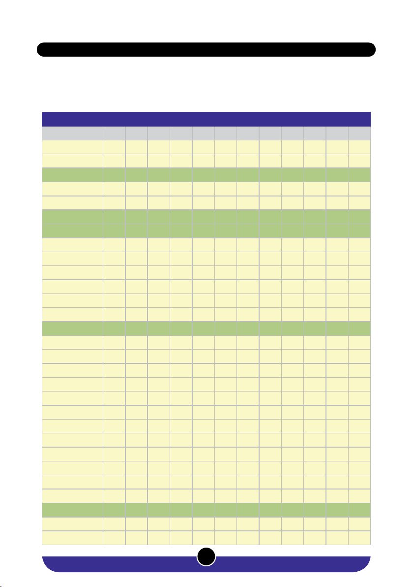
Please select your system combination according to the area you live in:
For low irradiation areas, please use combination as for low irradiation areas (highlighted in yellow in the
table). For high irradiation areas, please use combination as for high irradiation areas (highlighed in green
in the table).
Insulation kWh/m2/day
JAN FEB MAR APR MAY JUN JUL AUG SEP OCT NOV DEC
BELA-BELA 6,44 5,87 5,31 4,72 4,26 3,88 4,18 4,88 5,72 6,02 6,20 6,30
BETHAL 6,66 6,08 5,41 4,76 4,16 3,78 4,03 4,73 5,60 5,94 6,20 6,53
BLOEMFONTEIN 7,02 6,19 5,28 4,44 3,74 3,32 3,54 4,36 5,29 5,97 6,71 7,07
BOTSHABELO 6,90 6,10 5,23 4,44 3,78 3,35 3,57 4,35 5,30 5,82 6,59 6,95
BRITS 6,70 6,10 5,46 4,77 4,21 3,80 4,08 4,78 5,69 5,98 6,29 6,62
CAPE TOWN 7,93 7,02 5,63 4,06 2,91 2,50 2,67 3,41 4,63 6,16 7,44 7,96
DE AAR 7,58 6,60 5,46 4,35 3,54 3,03 3,31 4,20 5,19 6,31 7,19 7,80
DELMAS 6,66 6,08 5,41 4,76 4,16 3,78 4,03 4,73 5,60 5,94 6,20 6,53
DURBAN 5,57 5,18 4,75 4,01 3,41 3,01 3,17 3,72 4,32 4,53 4,83 5,44
EAST LONDON 5,68 5,27 4,44 3,69 3,15 2,70 2,85 3,53 4,29 4,78 5,35 5,74
EMALAHLENI 6,66 6,08 5,41 4,76 4,16 3,78 4,03 4,73 5,60 5,94 6,20 6,53
EMBALENHLE 6,39 5,83 5,19 4,54 3,99 3,66 3,88 4,57 5,43 5,63 6,03 6,28
JOHANNESBURG 6,70 6,10 5,46 4,77 4,21 3,80 4,08 4,78 5,69 5,98 6,29 6,62
KIMBERLEY 7,10 6,30 5,39 4,53 3,79 3,36 3,59 4,45 5,42 6,16 6,91 7,21
KLERKSDORP 6,55 5,92 5,24 4,58 4,04 3,64 3,92 4,67 5,57 5,86 6,36 6,57
MIDDELBURG 6,66 6,08 5,41 4,76 4,16 3,78 4,03 4,73 5,60 5,94 6,20 6,53
MOKOPANE 6,45 5,98 5,32 4,75 4,22 3,83 4,11 4,81 5,62 5,87 6,11 6,34
ORKNEY 6,55 5,92 5,24 4,58 4,04 3,64 3,92 4,67 5,57 5,86 6,36 6,57
PHALABORWA 6,10 5,69 5,07 4,51 4,00 3,60 3,77 4,47 5,16 5,28 5,72 6,00
POLOKWANE 6,45 5,98 5,32 4,75 4,22 3,83 4,11 4,81 5,62 5,87 6,11 6,34
PORT ELIZABETH 6,41 5,68 4,63 3,63 2,97 2,50 2,71 3,39 4,29 5,07 5,91 6,55
POTCHEFSTROOM 6,55 5,92 5,24 4,58 4,04 3,64 3,92 4,67 5,57 5,86 6,36 6,57
PRETORIA 6,70 6,10 5,46 4,77 4,21 3,80 4,08 4,78 5,69 5,98 6,29 6,62
RUSTENBURG 6,68 5,99 5,40 4,74 4,21 3,79 4,09 4,82 5,71 6,01 6,38 6,63
SOWETO 6,70 6,10 5,46 4,77 4,21 3,80 4,08 4,78 5,69 5,98 6,29 6,62
STILFONTEIN 6,55 5,92 5,24 4,58 4,04 3,64 3,92 4,67 5,57 5,86 6,36 6,57
UPINGTON 7,71 6,86 5,68 4,50 3,78 3,34 3,57 4,43 5,40 6,69 7,46 7,98
VIRGINIA 6,78 6,12 5,24 4,49 3,88 3,45 3,71 4,45 5,39 5,77 6,35 6,71
WELKOM 6,78 6,12 5,24 4,49 3,88 3,45 3,71 4,45 5,39 5,77 6,35 6,71
South African irradiation levels

www.geyserwise.co.za
6
Geyserwise TSE1 Controller
1.5m element connector cable 6m Black 6mm2 PV Cable
GeyserWise ECO MPPT
PV System Installers Guide __________________________ Installation
System components
PV Panels
Number and Size of PV panels depend
on the size of the geyser and region
(high or low irradiation) in which the PV
Waterheating system will be installed.
PTC Element
1500W AC, 900W DC or 2000W AC, 900W
DC. Screwboss or Flangemount available.

www.geyserwise.co.za
7
PV System Installers Guide __________________________ Installation
6m Red 6mm2 PV Cable
Flange – flange if required
30A Fuse and Fuseholder
Remote control cable between TSE and
MPPT and DC thermostat
Pre-Galvanised Solar Strut
The length of strut required depends
on the number of PV Panels used in the
system. Each panel requires 1m strut at the
bottom and 1m strut at the top.
PV Panel Mounting Clip
Stainless Steel temperature pocket
– only if a flange is required

www.geyserwise.co.za
8
Components’Technical Specications
PV Panels
It is important to note that the maximum size of the system is limited to 138 VOC (Open Circuit Voltage).
It is important to congure the PV panels in such a way that this open circuit voltage is not
exceeded.
250W PV Panels technical specications
Dimensions: 1,640 X 990 X 40 mm Vmp 30.43 V
VOC: 38.04 V Imp 8.22 A
ISC 8.56 A Weight 18 kg
The maximum number of 250W PV Panels that can be connected in series three:
3X 38.04 = 114.12V
If the installation requires four 250W PV panels, the panels must be connected as follows:
1. 2 Panels in series (2X 38.04 = 76.08V) 3. Then connect the 2 series sets in parallel
Voc = 76.08V, Ioc = 2X8.56 = 17.12 A
2. 2 Panels in series (2X 38.04 = 76.08V)
300W PV Panels technical specications
Dimensions: 1,957 X 990 X 40 mm Vmp 36.52 V
VOC: 45.65 V Imp 8.22 A
ISC 8.56 A Weight 21.50 kg
The maximum number of 300W PV Panels that can be connected in series is three:
3X 45.65 = 136.95V
If the installation requires four 300W PV panels, the panels must be connected as follows:
1. 2 Panels in series (2X 45.65 = 91.30V) 3. Then connect the 2 series sets in parallel Voc
= 91.30V, Ioc = 2X8.56 = 17.12 A
2. 2 Panels in series (2X 45.65 = 91.30V)
PV System Installers Guide __________________________ Installation

www.geyserwise.co.za
9
Components’Technical Specications
PTC Elements
Flangemount and screwboss types available (all 1 ¼“)
1500W AC, 900 DC
AC: Resistance at 25°C (Ω) 5-15 Ω Inrush Current (A) ≤20A
DC: Resistance at 25°C (Ω) 30-200 Ω Surface Temp. (°C) 240±10 °C
Material Stainless Steel Power (W)(AC) 1500±10% W
Rated Voltage 48 V (DC)/220 V (AC) Power (W)(DC) 900±10% W
Max Voltage 72 V (DC) /265 V (AC) Length (mm) 350±2mm
Withstanding Voltage (V) 270V/15min (220V) Diameter (mm) φ35±0.5mm
Insulating withstanding voltage Leak current ≤ 10mA
2000W AC, 900 DC
DC Resistance at 25°C (Ω) 5-15 Ω Surface Temp. (°C) 240±10 °C
AC Resistance at 25°C (Ω) 30-200 Ω Power (W) 2000±10% W
Material Stainless Steel Power (W) 900±10% W
Rated Voltage 48V (DC)/220 V (AC) Length (mm) 425±2mm
Max Voltage 72V (DC)/265V (AC) Diameter (mm) φ35±0.5mm
Inrush Current (A) ≤20A
PV System Installers Guide __________________________ Installation

www.geyserwise.co.za
10
Geyserwise ECO MPPT Technical Specications
• Maximum input voltage 46—138 VOC, 36—108 VMP
• Peak efficiency 98%
• Maximum output amps 25A
• Ambient temperature Up to 70°C but de-rated at 1A per degree at temperatures above 50°C. Do not
expose to direct sunlight.
• Environmental IP43
• Indications 2 LED’s
• Heating (input command from thermostat)
• Tracking (PV active)
• Power (device turned on)
• Inputs/Outputs - potential free
Geyserwise TSE1 Controller Technical specication
• Operating voltage 230VAC / 50HZ.
• Main relay contact rating 30A (max 4kW element).
• Operating voltage range 160V - 250V AC.
• Recommended ambient temperatures: -7 - 50°C; max 75°C
• Temperature display range 0 - 99°C.
• Temperature setting ranges 30 - 65°C (AC Settings)
• Temperature setting ranges 50 - 75°C (DC Settings)
• Change over switch to heat secondary geyser from PV array
• Heat failure - when increase at a rate of 4°C or less per hour, AC only.
• Mechanical thermal cut-out 90°C (300 manual resets) on AC only.
• Mechanical thermal cut-out 75°C on DC thermostat, 10 000 cycles.
• Thermal cut-out - Isolate live.
• Dry heat detection - empty cylinder.
• Temperature tolerance ± 5°C and manufacturing drift is less than 6°C.
• Temperature differential setting 1°C.
• Temperature probe failure detection for the tank.
• Temperature probe range for geyser is -30 to +130°C.
• Control box insulated - Class 1.
• Operating life - 50 000 cycles.
• SANS 181 compliant.
PV System Installers Guide __________________________ Installation

www.geyserwise.co.za
11
INSTALLATION TOOLS REQUIRED
• AC/DC Clamp meter
• Screwdriver set
• Socket Set
• Crimping Tool
• 4mm or 6mm (depending on distances) Black and Red Solar Flex Cable (No other cable may be used on
DC Connections)
• Twin and Earth wire for AC Connection on Geyserwise TSE Controller
INSTALLATION STEPS SUMMARY
Step 1 Read this manual thoroughly. In case of any ambiguities, contact our office for further advice.
Step 2 Always ensure familiarity with all local safety procedures.
Step 3 Mount the PV Panels.
Step 4 Install element.
Step 5 Install Geyserwise TSE Controller.
Step 6 Install Geyserwise ECO MPPT Controller.
Step 7 Recheck all connections.
Step 9 Connect DC live onto the fuse connection.
PV System Installers Guide __________________________ Installation

www.geyserwise.co.za
12
SAFETY PRECAUTIONS
Observe all precautions as set out in SANS 10142 when working with electricity.
Electricity on the geyser
An installer should always take precautions when working with electricity. The most important precautions
to perform before doing maintenance on a geyser are:
Test with a MULTIMETER to ensure that
there is no current on the wires. IMPORTANT
Make sure that there is no reading on the
multimeter.
Switch o the circuit breaker of the geyser
at the main DB. This is done to ensure that
there is no power supply to the geyser
Switch o the isolator switch in the roof.
The isolator switch acts as a switch to isolate
both the live an neutral from the main supply
should someone accidentally switch on the
main supply or the circuit breaker fails
PV System Installers Guide _____________________ Safety precautions

www.geyserwise.co.za
13
Electricity on PV Panels
PV modules can produce current and voltage when exposed to light of any intensity. Electrical current
increases with higher light intensity. DC voltage of 30 Volts or higher is potentially lethal. Contacting
the live circuitry of a PV system operating under light can result in lethal electric shock. De-energize PV
modules by removing them entirely from light or by covering the front surface with an opaque material.
Regard the safety regulations for live electrical equipment when working with modules that are exposed
to any light. Use insulated tools and do not wear metallic jewellery while working with PV modules.
In order to avoid arcing and electrical shock, do not disconnect electrical connections under load. Faulty
connections can also result in arcing and electrical shock. Keep connectors dry and clean, and ensure that
they are in proper working condition. Never insert metallic objects into the connectors, or modify them in
any way in order to secure an electrical connection.
Do not touch or handle PV modules with broken glass, separated frames or a damaged backsheet unless
the PV modules are first disconnected and you are wearing proper protective clothing. Avoid handling PV
modules when they are wet. Never touch electrical connections that are wet without protecting yourself
with insulated gloves.
Make sure that the fuse on the live side of the DC connection from the PV panels is not connected until
all other connections are completed. Also only turn on AC power once all connections are completed
and checked.
Mounting of PV Panels
Rooftop PV systems should only be installed on dwellings that have been formally analysed for structural
integrity, and confirmed to be capable of handling the additional weighted load of PV system components,
including PV modules, by a certified building specialist or engineer.
For your safety, do not attempt to work on a rooftop until safety precautions have been identified and
taken, including without limitation fall protection measures, ladders or stairways, and personal protective
equipment.
For your safety, do not install or handle PV modules under adverse conditions, including without limitation
strong or gusty winds, and wet or frosted roof surfaces.
PV System Installers Guide _____________________ Safety precautions

www.geyserwise.co.za
14
INSTALLATION OF THE PV PANELS
Each manufacturer of PV panels will make available instructions on how to best install its PV panels. Be
sure to read and follow instructions on the specific brand of PV panels used in the system. The below
information is based on information as contained in the guidance notes of Renesola PV panels.
General
Do not dismantle the Modules or tear up any labels.
Installation should be done by qualified professionals only.
Ensure that the correct connector pairs are used.
Do not touch the exposed cables or connectors.
De-energize PV modules by removing it entirely from light or by covering the front surface with an
opaque material.
System designers shall design an appropriate bracket and follow the instructions to fix the PV module
to the bracket.
Installation and maintenance shall be performed in accordance to all electrical safety regulations.
Do not stand on the modules.
Do not paint the modules or spray any material on the modules.
Always transport the modules carefully and according to the manufacturer’s instructions. Take care that
the modules are not scratched, as scratches may influence the efficiency of the modules.
Installation
STEP1
Choose the location of the PV panels - be sure to choose a location where the panels will be fully exposed
to the sun and that the areas are not shaded. Look out for shade produced by trees or other buildings. In
the Southern Hemisphere the panels should face north at an angle calculated according to your location
Optimal angle for xed solar panels depending on installation position
45˚
37˚ – 45˚
26˚ – 37˚
13˚ – 26˚
0˚ – 13˚
13˚ – 26˚
26˚ – 37˚
37˚ – 45˚
PV System Installers Guide ______________ Installation of the PV panels

www.geyserwise.co.za
15
for a latitude up to 25° take your latitude and multiply it by 0,87
for a latitude between 25° to 50° take your latitude multiply by 0,87. After that you will add 3,1 degrees
for a latitude over 50° the ideal angle is approximately 45° degrees.
You will need to know your current latitude to count out the ideal angle to position your solar panels in.
The easiest way to do this is to do a search for your location on Google maps and then right click on the
location and choose “what is here”. A green arrow will then appear. If you click on that arrow you will get
the GPS coordinates for that location on the map. The first numbers is the latitude of the location. Use
this number in your calculations. For example GPS coordinates for Goodwood, Cape Town is given below.
STEP 2
Use a bracket structure that can withstand high winds. The bracket structure must be made of durable,
corrosion resistant and UV resistant materials
STEP 3
Choose a fixing method:
33.9 x 0.87 = 29.50
Then add 3.1 degrees
29.5 + 3.1 = 32.60 degrees
100 Townsend St
Cape Town 7460
-33.906552, 18.540870
Installed by nut and bolt
Fix the module to the structure using the
pre-fabricated holes
Installed by xture
PV System Installers Guide ______________ Installation of the PV panels

www.geyserwise.co.za
16
PV system connection diagramme –
Three panels in Series
PV system connection diagramme –
Two Series, Two Series, then Parallel
250W
300W PV
panel
250W
300W PV
panel
250W
300W PV
panel
– – –+
250W or
300W PV
panel
250W or
300W PV
panel
250W or
300W PV
panel
250W or
300W PV
panel
– – – –+ + + ++ +
PV system connection diagramme – Two panels in Series
STEP 4
Grounding
Negative system grounding is recommended
The ground wire shall be bare copper wire with no
insulation sleeve. Wire cable with cross sectional
area of 4mm2 to 6mm2 is recommended and
ground clamp is recommended (See picture)
STEP 5
Wiring and connection
Use 6mm cable depending on the distance of the panels from the MPPT. 6mm cable for up to 20m.
For longer distances use 10mm Cable
Ensure that the correct connecters are used (At least 40 A)
PV System Installers Guide ______________ Installation of the PV panels
250W or
300W PV
panel
MPPT +
(Plug in using
supplied cables)
MPPT -
(Plug in using
supplied cables)
250W or
300 W PV
panel
– ++ –

www.geyserwise.co.za
17
Screw in type PTC AC/DC Element
Typically used on Tecron and Duratherm
geysers.
Can the background of the element be made
white or transparent?
Flangemount type element
Please specify the type of geyser the
element will be fitted on. Different flanges
available for Kwikot, GAP, Franke and
Heattech geysers. Please use the geysers
existing screws to mount the flange.
INSTALLATION OF THE ELEMENT
The element is a universal screwboss element suitable for geysers that are fitted with a screw-in element or
flange mount element. Please note that a separate flange must be purchased for flange mount elements.
Each brand of geyser has its own unique flange.
PV System Installers Guide ______________ Installation of the element
Gasket on element
Never remove as it seals in any water
between element and the geyser.

www.geyserwise.co.za
18
Screw in elements
Tools needed:
Phillips screwdriver
Screw-in element wrench
Your new element
Garden hose
Multi meter or circuit tester (to make sure power is off )
Installation steps
Be sure to use the same wattage, voltage, and flange style as your previous element.
1
Shut OFF electric power to water heater. See safety steps on page 12
2
Shut OFF cold water supply to the geyser, open the hot water faucet, attach a hose to the drain valve, open
the drain valve on the GEYSER and drain the water.
3
Remove access cover and fold back insulation.
4
Remove plastic terminal protector.
5
Check wires with a Multi Meter before attempting to
remove the wires.
6
Disconnect electric wires from element
7
Remove element using screw-in element wrench
8
Clean gasket area and threads
9
Install gasket on element
10
Install element
11
Close drain valve and turn ON cold water supply.
12
Allow all trapped air to escape from open hot water faucet until water has a constant flow, then close hot
water faucet. If leakage occurs, shut OFF cold water supply and tighten element or reposition gasket.
13
Inspect wiring. If corrosion is present on wiring, cut and strip wire 1/2”(only if wire is long enough). If corrosion
is still present, or wire is not long enough consult electrician for wire replacement and wire gauge selection.
Loose, corroded or faulty wiring connections can cause heat build-up or fire at wiring terminals.
PV System Installers Guide ______________ Installation of the element
This manual suits for next models
2
Table of contents
Popular Water Heater manuals by other brands

Haier
Haier ES8VQ1 (R) null

A.O. Smith
A.O. Smith CMC/SU-54 Specification sheet

STYLEBOILER
STYLEBOILER Smart Series Instructions for installation, use and maintenance

American Water Heater
American Water Heater BCL3 95T199 6NOX instruction manual

Sears
Sears 153.313230 owner's manual

Lochinvar
Lochinvar EJ 006 Series instruction manual

Amtrol
Amtrol ERTG Series Installation & operation instructions

John Wood
John Wood JWF307 Installation and operating instructions

Pentair
Pentair PSC Series owner's manual

CTC Union
CTC Union EcoZenith I 550 Installation and maintenance manual

Bosch
Bosch TR4000 Installation and operating instructions

PVI
PVI NICKELSHIELD PV 6452 1/04 Specification sheet