GEZE GC 403 WDS User manual

1
GEZE
GC 403 WDS
DE Windrichtungssensor
GB Wind direction transmitter
DE Montageanleitung
GB Installation instructions

GC 403 WDS
DE 2
Symbole und Darstellungsmittel
Symbole und Darstellungsmittel1
Warnhinweise
In dieser Anleitung werden Warnhinweise verwendet, um Sie vor Sach- und Personenschäden zu warnen.
Lesen und beachten Sie diese Warnhinweise immer.
X
Befolgen Sie alle Maßnahmen, die mit dem Warnsymbol und Warnwort gekennzeichnet sind.
X
Warnsymbol Warnwort Bedeutung
GEFAHR Gefahren für Personen.
Nichtbeachtung führt zu Tod oder schweren Verletzungen.
– VORSICHT Informationen zur Vermeidung von Sachschäden, zum Verständnis oder zum Optimie-
ren der Arbeitsabläufe.
Weitere Symbole und Darstellungsmittel
Um die korrekte Bedienung zu verdeutlichen, sind wichtige Informationen und technische Hinweise besonders
herausgestellt.
Symbol Bedeutung
bedeutet „Wichtiger Hinweis“
bedeutet „Zusätzliche Information“
XSymbol für eine Handlung: Hier müssen Sie etwas tun.
Halten Sie bei mehreren Handlungsschritten die Reihenfolge ein.
X
Produkthaftung2
Gemäß der im Produkthaftungsgesetz denierten Haftung des Herstellers für seine Produkte sind die in dieser
Broschüre enthaltenen Informationen zu beachten. Die Nichtbeachtung entbindet den Hersteller von seiner
Haftungspicht.
Sicherheitshinweise3
Diese Anleitung richtet sich an ausgebildetes Fachpersonal. Grundlegende Arbeitsschritte werden nicht erläutert.à
Evtl. Gewährleistungsansprüche setzen fachgerechte Montage, Installation und Wartung nach den Angabenà
des Herstellers voraus.
Nur GEZE Originalteile für Reparaturarbeiten verwenden.à
Eigenmächtige Veränderungen an der Anlage schließen eine Haftung von GEZE für daraus resultierendeà
Schäden aus.
GEFAHR Die Gerätemontage und deren Anschluss darf nur durch eine Fachrma nach den
Vorschriften von VDE und des örtlichen EVUs vorgenommen werden.
Metallteile müssen wegen Blitzschutz entsprechend den rechtlichen Bestimmun-
gen und Normen geerdet werden.
Produktbeschreibung4
Anwendung4.1
Automatischer Melder zum windrichtungsabhängigen Önen und Schließen von elektromotorisch betriebenen
Gebäudeönungen im RWA-Fall.

GC 403 WDS
DE 3
Montage
Lieferumfang4.2
Wind- und Regensensor Set GC 401 RS /
GC 402 W VS (Mat. Nr. 140229)
Windrichtungssensor GC 403 WDS
(Mat. Nr. 140228)
Bestehend aus:
Windgeschwindigkeits-1
Sensor GC 402 WVS
Klemmring2
Regensensor (24 V DC/AC)3
mit Gerätekonsole GC 401 RS
Konsole (Aluminium) für4
Wand- oder Mastmontage
Bestehend aus:
Windrichtungssensor GC5
403 WDS
Klemmring6
Konsole für Mast- oder7
Wandmontage
Klemmdose8
110 x 110 x 66 mm
zum
Anschluss an MBZ 300.
-
Kabel: 6 x 0,34 mm²
LIYY, 3 m lang (o. A.)
Funktionsweise einer windrichtungsabhängigen Steuerung (nach DIN 18232-2)4.3
Bei Windstille und Windgeschwindigkeiten < 1 m/s werden alle NRA/RWA und Zuluftächen in den Außenwän-
den des Rauchabschnittes geönet. Bei Geschwindigkeiten > 1 m/s werden nur die Zuluft- und NRA/RWA - Flä-
chen in den jeweils windabgewandten Wandächen geönet. Die Windgeschwindigkeiten und Windrichtungen
werden oberhalb des Daches gemessen und über einen Zeitraum von 10 ± 2 Minuten gemittelt.
Betriebsvoraussetzungen MBZ 300:4.4
Anschluss und Konguration setzen zusätzlich zum Windrichtungssensor, Windsensor und ggf. Regensensor
voraus:
Weather-Modul WMà
Lizenzierte Software zum Kongurieren der MBZ 300à
Zum Anschluss vgl. Zentralen-Beschreibung, zur Einstellung vgl. Beschreibung der Software MBZ 300.
Montage5
Zur Montage des Windgeschwindigkeits- und Regensensors siehe Montageanleitung „Wind- und Regensensor
Set GC 401 RS / GC 402 WVS“ (Mat. Nr. 143015)
Für den Anschluss an die RWA-Zentrale MBZ 300 siehe Zentralen-Beschreibung; Konguration der windrich-
tungsabhängigen Steuerung setzt bei der MBZ 300 eine lizenzierte Software des Zentralenherstellers voraus.
Montage des Windrichtungssensors5.1
Der Schaltpunkt für den Windgeschwindigkeits-Sensor für den Lüftungsbetrieb muss den örtlichen Gegebenhei-
ten angepasst werden.
Werkseitig ist die kleinste Windgeschwindigkeit eingestellt.
Die Sensoren sind an einer dem Wetter zugewandten Gebäudeseite zu montieren. Umliegende Gebäudeteileà
sowie elektrische Geräte dürfen deren Funktion nicht beeinträchtigen.
Die Konsole muss auch bei extremen Wetterverhältnissen (Sturm) sicheren Halt gewährleisten.à
Windrichtungssensor und Windgeschwindigkeitssensor für ein einwandfreies Messergebnis an einemà
gemeinsamen Mast montieren.
Der Montageort muss so gewählt werden, dass sich Windrichtung und Windgeschwindigkeit optimal ermit-à
teln lassen (z.B. oberhalb des Daches)
Die Nord-Markierung des Windrichtungssensors muss exakt nach Norden gerichtet sein.à

GC 403 WDS
DE 4
Wartung, Pege, Reparatur
Montage von Windrichtungssensor an Wand-/ Mastkonsole5.2
Windblatt (3) in Halterung des Drehkopfs
X
(4) einschieben bis Windblatt einras-
tet. Um Beschädigungen des Lagers zu
vermeiden, Drehkopf (und nicht Gehäuse-
rohr) festhalten.
Konsole an Wand oder Mast befestigen.
X
Wird statt der Konsole ein bauseitiges
Rohr verwendet, muss dessen Durchmes-
ser mind. 40 mm betragen.
Windrichtungssensor durch Klemmring
X
mit Konsole (2) verbinden.
Nord-Markierung1
Konsole2
Windblatt3
Drehkopf4
Mutter (6) auf Schraube (7) drehen und in
X
Klemmring mindestens 15 mm einschrauben.
Gehäuserohr vom WDS bis zum Anschlag in
X
Klemmring stecken.
X
Nord-Markierung genau nach Norden ausrichten
X
(Kompass) und Klemmschrauben (5) anziehen.
Gehäuserohr mit Klemmring auf Konsole ste-
X
cken, mit Schraube (7) befestigen und mit Mutter
(6) kontern.
Klemmschrauben5
Mutter6
Schraube7
WDS8
Klemmring9
Konsole (Ø 36 mm)10
mind. Ø 20 mm (max. Ø 36 mm)11
Kabel innen durchführen12
Abnahmeprüfung5.3
Nach dem betriebsfertigen Einbau der Anlage ist am Verwendungsort deren einwandfreie Funktion und vor-
schriftsmäßige Installation durch eine Abnahmeprüfung festzustellen. Abnahmeprüfung durch autorisiertes
Fachpersonal.
Wartung, Pege, Reparatur6
Um eine zuverlässige Funktion auf Dauer sicherzustellen, ist es unerlässlich, die Anlage von einer autorisierten
Fachrma reinigen und mindestens jährlich warten zu lassen.
Die Einbaurma muss den Betreiber der Anlage auf diesen Teil der Montageanleitung aufmerksam machen, und
diese sowie die Benutzerinformation dem Betreiber aushändigen.

GC 403 WDS
Notizen:

GC 403 WDS
GB 2
Key to symbols
Key to symbols1
Warning
In these instructions, warnings are used to warn against material damage and injuries.
Always read and observe these warnings.
X
Follow all instructions marked with the warning symbol and the word WARNING.
X
Warning
symbol
Warning Meaning
DANGER Danger for people.
Non-observance can result in death or serious injuries.
– CAUTION Information to prevent damage to property and to understand and optimise workow.
Further symbols used in these instructions
Important information and technical notes are emphasised to illustrate the correct operation.
Symbol Meaning
means “Important note“
means “Additional information”
XSymbol for a user action. Here you have to take an action.
Observe the sequence if there are several action steps.
X
Product liability2
According to the denition of manufacturer‘s liability for his products in the Product Liability Act, the informati-
on contained in this brochure are to be followed. Ignoring this information absolves the manufacturer from his
liability.
Safety instructions3
Installation, commissioning and repairs must be performed by a specialist.à
Basic techniques are not explained.
Warrenty claims require professional installation and service according to the guidelines of the manufacturer.à
Use only GEZE original parts for repair work.à
Unauthorised modications of the system excludes GEZE from the liability for any resulting damage.à
DANGER All electrial connections should be made by a properly electricain and connected in
accordance with the
appropriate standards of the country of installation.
Ground metal parts for protection against lightning according to the national safety regulations.
Product description4
Application4.1
Automatic detectors for electromotive opening and closing of building vents depending on weather in the case
of smoke and heat extraction (RWA).

GC 403 WDS
GB 3
Assembly
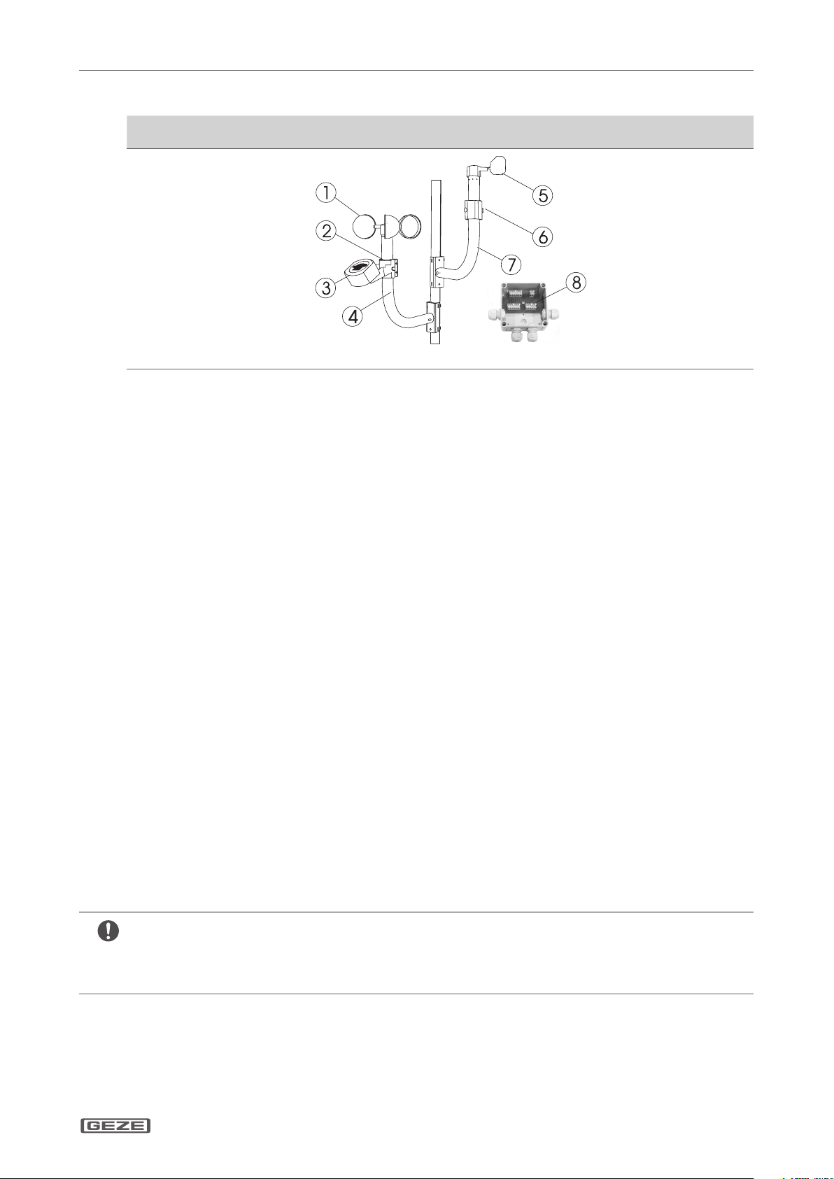
Scope of delivery4.2
Wind- and rain sensor set GC 401 RS /
GC 402 W VS (Mat. No. 140229)
Wind direction transmitter
GC 403 WDS (Mat. No. 140228)
Consists of:
Wind speed sensor GC 4021
WVS
Clamp ring2
Rain sensor (24 V DC/AC)3
with equipment bracket
GC 401 RS
Bracket (aluminium) for4
pole or wall mounting
Consists of:
Wind direction transmit-5
ter GC 403 WDS
Clamp ring6
Bracket for pole or wall7
mounting
Connection box8
110 x 110 x 66 mm
to
connect to MBZ 300.
-
Cable: 6 x 0,34 mm²
LIYY, 3 m long (w/o Fig.)
Functioning of a wind direction-dependent control (according to DIN 18232-2)4.3
With no wind and wind speeds < 1 m/s, all NRA/RWA and air supply areas in the outer walls of the smoke section
are opened. At speeds > 1 m/s, only the supply air and NRA/RWA areas in the respective downwind wall surfaces
are opened. The wind speeds and wind directions are measured above the roof and averaged over a period of 10
± 2 minutes.
Operating requirements MBZ 300:4.4
In addition to the wind direction transmitter, connection and conguration requires wind sensor and, if necessary,
rain sensor:
Weather module WMà
Licensed software for conguring the MBZ 300à
See the central description for connection, and description of the software MBZ 300 for setting.
Assembly5
To mount the wind speed and rain sensor, see Installation Instructions „Wind and Rain Sensor Set GC 401 RS / GC
402 WVS“ (Mat. No. 143015)
For the connection to the RWA centre MBZ 300, see description of the centre; conguration of the wind direction-
dependent control for the MBZ 300 requires a licensed software of the manufacturer of the centre.
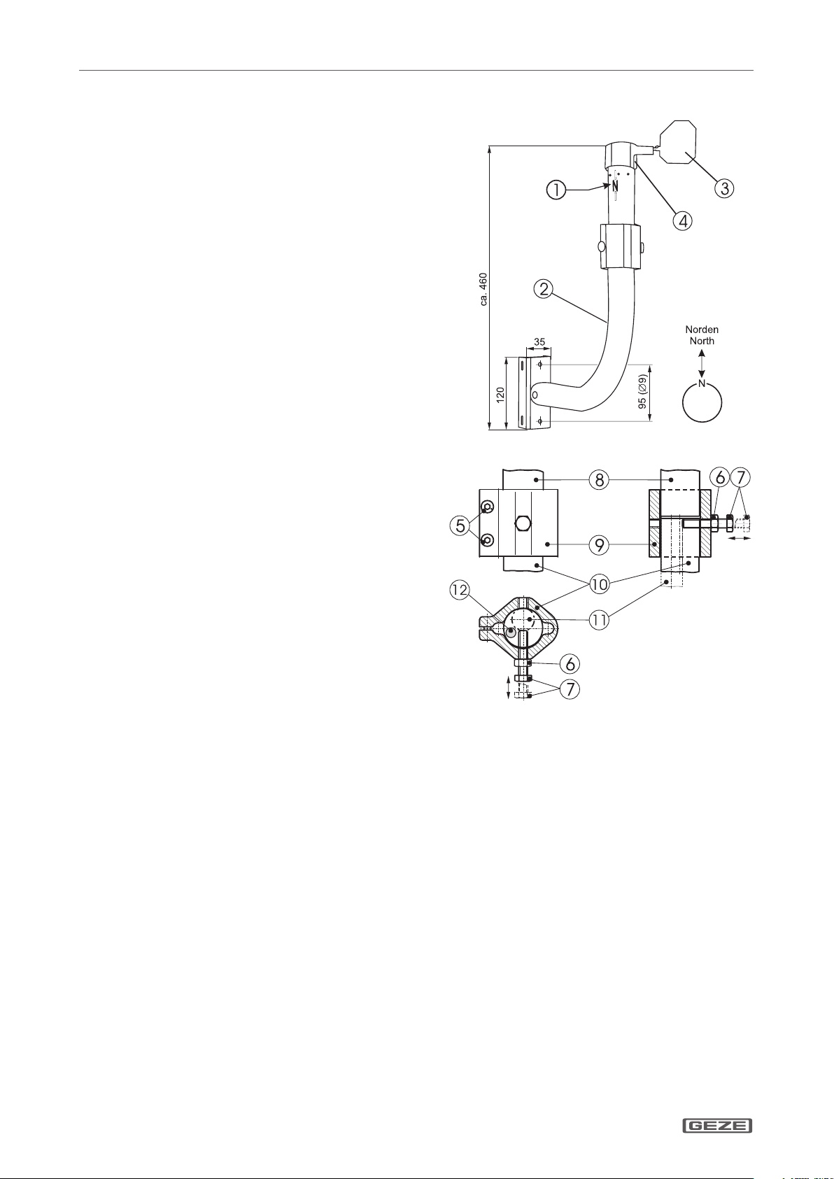
Installation of the wind direction transmitter5.1
The switching point for the wind speed sensor for the ventilation operation must be adapted to local conditions.
The smallest wind speed is set at the factory.
The sensors are mounted on the side of the building that faces the weather. Surrounding buildings andà
electrical equipment must not impair their function.
The console must ensure a secure hold even in extreme weather conditions (storm).à
Mount wind direction transmitter and wind speed sensor on one pole for perfect measurement results.à
The mounting position must be chosen in such a way that wind direction and wind speed can be ideallyà
determined (e.g. above the roof).
The north-marking of the wind direction transmitter must face exactly north.à

GC 403 WDS
GB 4
Maintenance, servicing, repairs
Installation of wind direction transmitter on wall/pole console5.2
Insert wind blade (3) in the mounting bra-
X
cket of the rotating head (4) till the blade
snaps in. To avoid damage to the bearing,
rmly hold rotating head (and not the
housing tube).
Attach console to wall or pole. If an on-
X
site pipe is used instead of the console, its
diameter must be at least 40 mm.
Connect wind direction transmitter with
X
console (2) using clamping ring.
North-marking1
Bracket2
Wind blade3
Rotation head4
Turn the nut (6) on screw (7) and screw both min.
X
15 mm into the clamp ring (1).
Insert housing tube from WDS fully into clam-
X
ping ring.
Align the north-marking precisely to the north
X
(using compass) and tighten clamping screws (5).
Insert housing tube with clamping ring in conso-
X
le, secure with screw (7) and lock with nut (6).
Clamp screws5
Locknut6
Screw7
WDS8
Clamp ring9
Bracket (Ø 36 mm)10
min. Ø 20 mm (max. Ø 36 mm)11
Run the cable inside12
Testing for acceptance5.3
An acceptance test must be carried out in order to ascertain the correct function and installation according to
the regulations once the installation has been completed on site. Acceptance test to be performed by authorised
personnel.
Maintenance, servicing, repairs6
The wind direction transmitter should be inspected at regular intervals, at least annually. Keep transmitter and
bracket clean for faultless operation.
The installing company must alert the operator of the system to this part of the mounting instructions and hand
it over to the operator together with the user information.

GC 403 WDS
Notes:

GC 403 WDS
Notes:


Germany
GEZE Sonderkonstruktionen GmbH
Planken 1
97944 Boxberg-Schweigern
Tel. +49 (0) 7930-9294-0
Fax +49 (0) 7930-9294-10
E-Mail: [email protected]
Germany
GEZE GmbH
Niederlassung Nord/Ost
Bühringstraße 8
13086 Berlin (Weissensee)
Tel. +49 (0) 30-47 89 90-0
Fax +49 (0) 30-47 89 90-17
E-Mail: [email protected]
Germany
GEZE GmbH
Niederlassung West
Nordsternstraße 65
45329 Essen
Tel. +49 (0) 201-83082-0
Fax +49 (0) 201-83082-20
E-Mail: [email protected]
Germany
GEZE GmbH
Niederlassung Mitte
Adenauerallee 2
61440 Oberursel (b. Frankfurt)
Tel. +49 (0) 6171-63610-0
Fax +49 (0) 6171-63610-1
E-Mail: frankfurt.d[email protected]
Germany
GEZE GmbH
Niederlassung Süd
Breitwiesenstraße 8
71229 Leonberg
Tel. +49 (0) 7152-203-594
Fax +49 (0) 7152-203-438
E-Mail: [email protected]
Germany
GEZE Service GmbH
Reinhold-Vöster-Straße 25
71229 Leonberg
Tel. +49 (0) 7152-9233-0
Fax +49 (0) 7152-9233-60
E-Mail: service-inf[email protected]
Germany
GEZE Service GmbH
Niederlassung Berlin
Bühringstraße 8
13086 Berlin (Weissensee)
Tel. +49 (0) 30-470217-30
Fax +49 (0) 30-470217-33
E-Mail: service-inf[email protected]
Austria
GEZE Austria GmbH
Wiener Bundesstrasse 85
5300 Hallwang b. Salzburg
Tel. +43-(0)662-663142
Fax +43-(0)662-663142-15
E-Mail: austria.at@geze.com
Baltic States
GEZE GmbH Baltic States oce
Dzelzavas iela 120 S
1021 Riga
Tel. +371 (0) 67 89 60 35
Fax +371 (0) 67 89 60 36
E-Mail: oce-latvia@geze.com
Benelux
GEZE Benelux B.V.
Leemkuil 1
Industrieterrein Kapelbeemd
5626 EA Eindhoven
Tel. +31-(0)40-26290-80
Fax +31-(0)40-26 290-85
E-Mail: benelux.nl@geze.com
Bulgaria
GEZE Bulgaria - Trade
Representative Oce
61 Pirinski Prohod, entrance „B“,
4th oor, oce 5,
1680 Soa
Tel. +359 (0) 24 70 43 73
Fax +359 (0) 24 70 62 62
E-Mail: oce-bulgaria@geze.com
China
GEZE Industries (Tianjin) Co., Ltd.
Shuangchenzhong Road
Beichen Economic Development
Area (BEDA)
Tianjin 300400, P.R. China
Tel. +86(0)22-26973995-0
Fax +86(0)22-26972702
E-Mail: Sales-info@geze.com.cn
China
GEZE Industries (Tianjin) Co., Ltd.
Branch Oce Shanghai
Unit 25N, Cross Region Plaza
No. 899, Ling Ling Road,
XuHui District
200030 Shanghai, P.R. China
Tel. +86 (0)21-523 40 960
Fax +86 (0)21-644 72 007
E-Mail: chinasal[email protected]
China
GEZE Industries (Tianjin) Co., Ltd.
Branch Oce Guangzhou
Room 17C3
Everbright Bank Building, No.689
Tian He Bei Road
510630 Guangzhou, P.R. China
Tel. +86(0)20-38731842
Fax +86(0)20-38731834
E-Mail: chinasal[email protected]
China
GEZE Industries (Tianjin) Co., Ltd.
Branch Oce Beijing
Room 1001, Tower D
Sanlitun SOHO
No. 8, Gongti North Road,
Chaoyang District,
100027 Beijing, P.R.China
Tel. +86-(0)10-5935 9300
Fax +86-(0)10-5935 9322
E-Mail: chinasal[email protected]
China
GEZE Industries (Tianjin) Co., Ltd.
Branch Oce Singapore
21, Bukit Batok Crescent,
No. 23-75, Wcega Tower,
Singapore 658065
Tel. +65-6846 1338
Fax +65-6846 9353
E-Mail: gezesea@geze.com.sg
France
GEZE France S.A.R.L.
ZAC de l’Orme Rond
RN 19
77170 Servon
Tel. +33-(0)1-606260-70
Fax +33-(0)1-606260-71
E-Mail: france.fr@geze.com
Hungary
GEZE Hungary Kft.
Bartók Béla út 105-113.
Budapest
H-1115
Tel. +36 (1) 481 4670
Fax +36 (1) 481 4671
E-Mail: oce-hungar[email protected]
Iberia
GEZE Iberia S.R.L.
Pol. Ind. El Pla
C/Comerc, 2-22, Nave 12
08980 Sant Feliu de Llobregat
(Barcelona)
Tel. +34 9-02 19 40 36
Fax +34 9-02 19 40 35
E-Mail: info@geze.es
India
GEZE India Private Ltd.
MF2 & 3, Guindy Industrial Estate
Ekkattuthangal
Chennai - 600 097
Tamilnadu
Tel. +91 (0) 44 30 61 69 00
Fax +91 (0) 44 30 61 69 01
E-Mail: oce-ind[email protected]
Italy
GEZE Italia Srl
Via Giotto, 4
20040 Cambiago (MI)
Tel. +3902950695-11
Fax +3902950695-33
E-Mail: italia.it@geze.com
Italy
GEZE Engineering Roma Srl
Via Lucrezia Romana, 91
00178 Roma
Tel. +3906-7265311
Fax +3906-72653136
E-Mail: roma@geze.biz
Kazakhstan
GEZE Central Asia
050061, Almaty, Kasakhstan
Rayimbek ave. 348, A, oce 310
Tel. +7 (0) 72 72 44 78 03
Fax +7 (0) 72 72 44 78 03
E-Mail: oce-kazakhstan@geze.com
Poland
GEZE Polska Sp.z o.o.
ul. Annopol 21
03-236 Warszawa
Tel. +48 (0)22 440 4 440
Fax +48 (0)22 440 4 400
E-Mail: [email protected]
Romania
GEZE Romania S.R.L.
IRIDE Business Park
Building nr. 10, level 2
Str. Dimitrie Pompei nr. 9–9a
RO-020335 Bucharest, sector 2
Tel. +40 (0) 316 201 257
Fax +40 (0) 316 201 258
E-Mail: oce-rom[email protected]
Russian Federation
GEZE GmbH Representative
Oce Russia
Kolodesnij pereulok3, str. 25
Oce Nr. 5201-5203
107076 Moskau
Tel. +7 (0) 49 55 89 90 52
Fax +7 (0) 49 55 89 90 51
E-Mail: oce-r[email protected]
Scandinavia
GEZE Scandinavia AB
Mallslingan 10
Box 7060
18711 Täby, Sweden
Tel. +46(0)8-7323-400
Fax +46(0)8-7323-499
E-Mail: [email protected]
Scandinavia
GEZE Norway
Industriveien 34 B
2072 Dal
Tel. +47(0)639-57200
Fax +47(0)639-57173
E-Mail: [email protected]
Scandinavia
GEZE Finland
Postbox 20
15871 Hollola
Tel. +358(0)10-4005100
Fax +358(0)10-4005120
E-Mail: nland.[email protected]
Scandinavia
GEZE Denmark
Mårkærvej 13 J-K
2630 Taastrup
Tel. +45(0)46-323324
Fax +45(0)46-323326
E-Mail: danmark.se@geze.com
South Africa
DCLSA Distributors (Pty.) Ltd.
118 Richards Drive, Midrand,
Halfway House Ext. 111
P.O. Box 7934
Midrand 1685
Tel. +27(0)113158286
Fax +27(0)113158261
E-Mail: info@dclsa.co.za
Switzerland
GEZE Schweiz AG
Bodenackerstrasse 79
4657 Dulliken
Tel. +41-(0)62-2855400
Fax +41-(0)62-2855401
E-Mail: schweiz.ch@geze.com
Turkey
GEZE GmbH Türkiye - İstanbul
İrtibat Bürosu
Ataşehir Bulvarı, Ata 2/3
Plaza Kat: 9 D: 84 Ataşehir
Kadıköy / İstanbul
Tel. + 90 (0) 21 64 55 43 15
Fax + 90 (0) 21 64 55 82 15
E-Mail: o[email protected]
Ukraine
Repräsentanz GEZE Ukraine TOV
ul. Viskoznaya, 17, building 93-B,
oce 12
02094 Kiev
Tel. +38 (0) 44 501 22 25
Fax +38 (0) 44 499 77 25
E-Mail: oce-ukraine@geze.com
United Arab Emirates/GCC
GEZE Middle East
P.O. Box 17903
Jebel Ali Free Zone
Dubai
Tel. +971(0)4-8833112
Fax +971(0)4-8833240
E-Mail: geze@emirates.net.ae
United Kingdom
GEZE UK Ltd.
Blenheim Way
Fradley Park
Licheld
Staordshire WS13 8SY
Tel. +44(0)1543443000
Fax +44(0)1543443001
E-Mail: info.uk@geze.com
GEZE GmbH
P.O.Box 1363
Reinhold-Vöster-Straße 21–29
71229 Leonberg
Germany
Tel.: 0049 7152 203-0
Fax: 0049 7152 203-310
www.geze.com
143014-00
Table of contents
Languages:
Popular Transmitter manuals by other brands

Nautel
Nautel VS300 troubleshooting manual

Rae
Rae RAEGuard EC user guide

Dwyer Instruments
Dwyer Instruments AVUL Series Installation and operating instructions

GESTRA
GESTRA LRGT 16-3 Installation & operating manual

Emerson
Emerson Micro Motion 1600 installation manual

Crestron
Crestron DM-TX-4KZ-202-C quick start