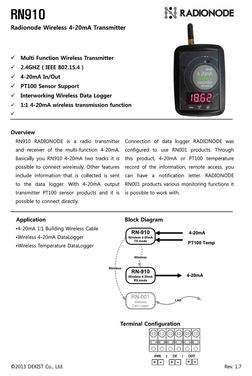
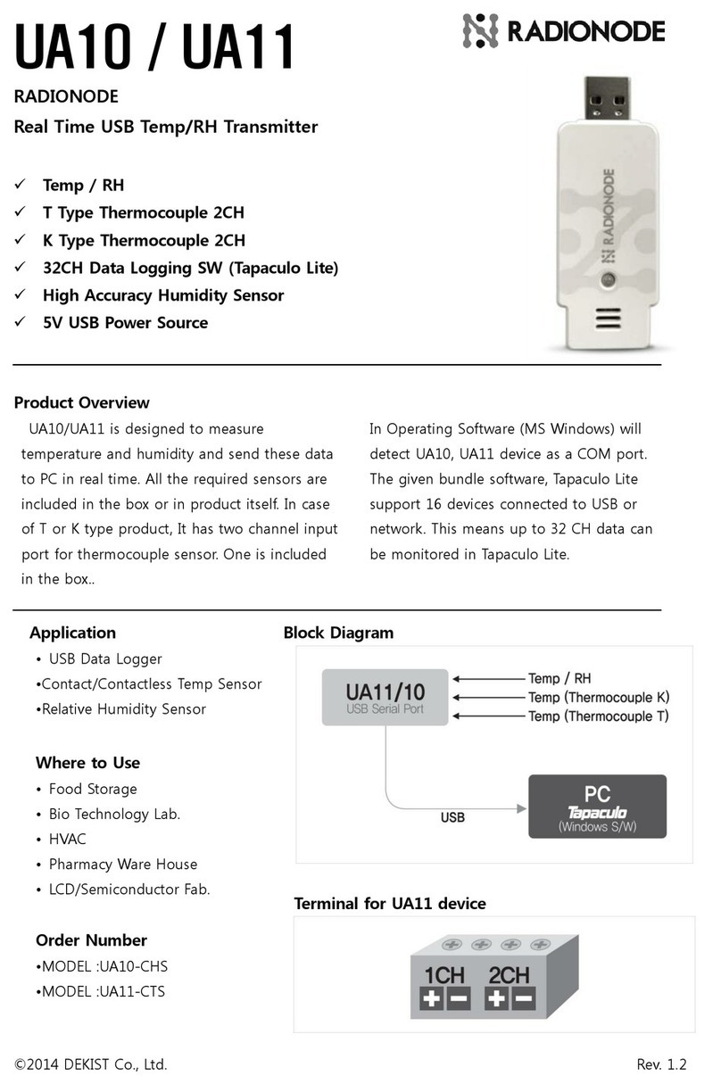
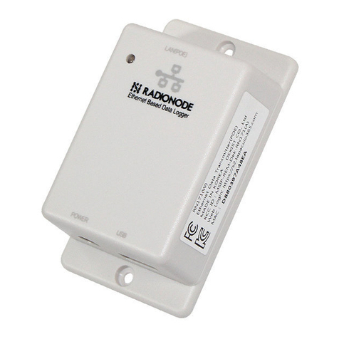
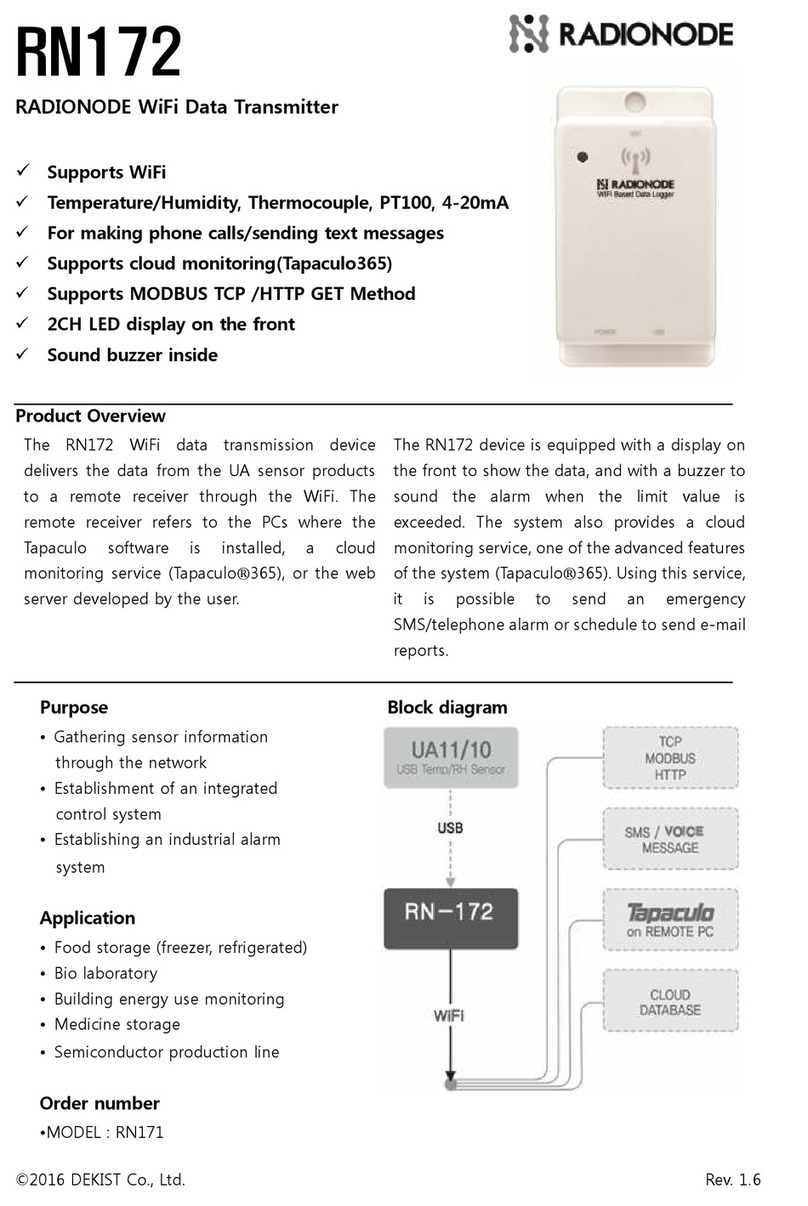
Radionode RN171WC User manual

User Manual
Ethernet Sensor Data Transmitter
RN171WC
Keep this document nearby so that it may be referred to when needed.2021 | Rev. 1.03

02
Introduction Configuration Installation Tapaculo Lite Customer Service
Information
Telnet
Commands
HTTP Radionode
Protocol V1
HTTP Radionode
Protocol V2
Modbus
Registration
About this Manual Radionode365
CONTENTS
About this Manual 04
Intellectual Property Rights 04
Notational Conventions 04
Introduction 05
Key Features 05
Exterior 06
Compatible UA Sensors 06
Accessories 07
Specifications 07
Configuration 08
Network 09
System 10
Alarm 11
Customer Server 12
Modbus 13
Installation 14
Installation 14
Connecting Network Cable 14
Connecting UA Sensor 15
Display 16
Radionode
365 17
Adding Devices from Your Smartphone 18
Adding Devices from Your Computer 21

03
Introduction Configuration Installation Tapaculo Lite Customer Service
Information
Telnet
Commands
HTTP Radionode
Protocol V1
HTTP Radionode
Protocol V2
Modbus
Registration
About this Manual Radionode365
Tapaculo Lite 24
Installing Software 24
Starting Tapaculo Lite 24
Customer Service Information 27
Manufacturer Contact Information 27
Warranty 27
Limit of Liability 27
Certifications 28
Telnet Commands 29
HTTP Radionode Protocol V1 30
Data-in 30
Backup-in 32
Timestamp 33
HTTP Radionode Protocol V2 34
Check-in 34
Data-in 36
Modbus Registration 37
Order List 38
UA Sensor 38
Accessories 39

04
Introduction Configuration Installation Radionode365 Tapaculo Lite Customer Service
Information
Telnet
Commands
HTTP Radionode
Protocol V1
HTTP Radionode
Protocol V2
Modbus
Registration
About
this
Manual
This document contains instructions for usage and installation of the
RADIONODE®RN171WC. Product specifications and certain features
herein may be subject to change without prior notice. Figures used
in this manual are for explanatory purposes only, and may differ
from your system depending on installation conditions. Software
screenshots can be changed after software updates.
Intellectual
Property
Rights
© 2021 DEKIST Co., Ltd.
All contents and figures herein are property of DEKIST Co., Ltd.
Reproduction or redistribution of all or part of this document in any
way is not permitted without prior consent from DEKIST.
Notational
Conventions
Failure to follow instructions marked with "Warning" may
result in slight injury to the user.
Failure to follow instructions marked with "Caution" may
result in equipment damage or malfunction.
Additional helpful information is marked with "Note".
About this Manual

05
Configuration Installation Radionode365 Tapaculo Lite Customer Service
Information
Telnet
Commands
HTTP Radionode
Protocol V1
HTTP Radionode
Protocol V2
Modbus
Registration
About this Manual
Introduction
The RADIONODE RN171WC is a data transmitter for UA Series
sensors that uses a network connection to send measurements to
the Radionode365 server or Tapaculo Lite program.
3BEJPOPEF
5BQBDVMPm-JUF
Key Features Key features of RN171WC include:
●Compatibility with a wide variety of UA sensors.
●Transmission of measurements over the Internet to
Radionode365 or customer servers. See Radionode365 on page
17.
●Transmission of measurements over the local network to the
computer where Tapaculo Lite is installed. See Tapaculo Lite on
page 24.
●Telnet connection to your device.
●Read measurements with Modbus communications using PLCs
or other devices.
●PoE support.
Introduction

06
Configuration Installation Radionode365 Tapaculo Lite Customer Service
Information
Telnet
Commands
HTTP Radionode
Protocol V1
HTTP Radionode
Protocol V2
Modbus
Registration
About this Manual
Exterior
3
4
1 52
❶ Display
❹ USB Port
❷ Indicator
❺ Ethernet Port
❸ Power Jack
Compatible
UA Sensors
The following UA sensors are compatible with the RN171WC.
UA10 Temperature, RH
UA11-K Temperature (Type K Thermocouple)
UA11-T Temperature (Type T Thermocouple)
UA13 Temperature (PT100)
UA20A 4 〜20 mA
UA20B 0 〜20 mA
UA20C 0 〜1 V
UA50 Total Volatile Organic Compounds (tVOC)
UA52-O2-25-F Oxygen (O₂), atmospheric pressure
UA52-CO2-20 Carbon dioxide (CO₂)
UA53-CO-1000 Carbon monoxide (CO)
UA53-NO2-50 Nitrogen dioxide (NO₂)
UA53-SO2-50 Sulfur Dioxide (SO₂)
UA54-NH3-100 Ammonia (NH₃)
UA54-H2S-50 Hydrogen sulfide (H₂S)
UA54-HCL-20 Hydrogen chloride (HCl)
UA54-EO-10 Ethylene oxide (C₂H₄O)
UA54-C2H4 Ethylene (C₂H₄)
UA54-H2-4 Hydrogen (H₂)
UA54-O2-21 Oxygen (O₂)
UA59 Carbon dioxide (CO₂)
Introduction

07
Configuration Installation Radionode365 Tapaculo Lite Customer Service
Information
Telnet
Commands
HTTP Radionode
Protocol V1
HTTP Radionode
Protocol V2
Modbus
Registration
About this Manual
Accessories The RN171WC comes with the following accessories:
UA Sensor
Protective Cover
USB Cable
Power Adapter (Optional)
Sensor Stickers
We recommend using a PoE (Power over Ethernet) supported router.
When connected to a PoE router, an adapter is not required, as
power is supplied through a network cable.
Specifications
50.4 mm
35.1 mm
90 mm
70 mm
51.5 mm
40.5 mm
Product name RN171 plus
Model name RN171WC
Ethernet 100 Mbps
Modbus Port 502
Telnet Port TCP: 23, UDP: 50000
USB 2.0
Power DC 6 V or PoE 48 V (IEEE 802.3af/802.3at)
Power consumption 1.9 W
Size H90 × W50.4 × D40.5 mm (with sensor
protective cover, total length is 141.9 mm)
Introduction

08
Introduction Installation Radionode365 Tapaculo Lite Customer Service
Information
Telnet
Commands
HTTP Radionode
Protocol V1
HTTP Radionode
Protocol V2
Modbus
Registration
About this Manual
Configuration
Before installing, connect the RN171WC to your computer and
change the settings using the Radionode Terminal program. Install
Radionode terminal by downloading from the Radionode website
(www.radionode365.com).
Without a power connection, connect RN171WC to your computer
using a USB cable. will appear on the display.
Run the Radionode terminal. If the screen background is blue-green,
the device has been recognized. Enter "radionode114radionode114" to call five
different device information menus.
1.Network Setup.1.Network Setup.
2.System Setup.2.System Setup.
3.Buzzer/Siren Setup.3.Buzzer/Siren Setup.
4.HTTP Destination Setup.4.HTTP Destination Setup.
5.MODBUS TCP Setup.5.MODBUS TCP Setup.
Enter the corresponding number to select the menu.
Configuration

09
Introduction Installation Radionode365 Tapaculo Lite Customer Service
Information
Telnet
Commands
HTTP Radionode
Protocol V1
HTTP Radionode
Protocol V2
Modbus
Registration
About this Manual
Network Select 1.Network Setup1.Network Setup menu to configure the network that your
device will use. Parameters will appear with their current settings.
Enter "qq" to return to the parent menu.
A.Set DHCP [OFF]A.Set DHCP [OFF]
Select "OffOff" and configure as shown below to use a static IP
address:
B.Set IP Address [xxx.xxx.xxx.xxx]B.Set IP Address [xxx.xxx.xxx.xxx]
Enter the IP address assigned to RN171WC.
C.Set GATEWAY Address [192.168.xxx.xxx]C.Set GATEWAY Address [192.168.xxx.xxx]
Enter the gateway IP address.
D.Set DNS1 Address [192.168.xxx.xxx]D.Set DNS1 Address [192.168.xxx.xxx]
Enter the IP address of the first DNS server.
E.Set DNS2 Address [xxx.xxx.xxx.xxx]E.Set DNS2 Address [xxx.xxx.xxx.xxx]
Enter the IP address of the second DNS server.
F.Set SUBNET MASK [255.255.255.000]F.Set SUBNET MASK [255.255.255.000]
Enter the subnet mask.
G.Set VMAC [xxxx0000xxxx]G.Set VMAC [xxxx0000xxxx]
Enter the address that will be used as the virtual MAC address.
H.Set UDP Broadcasting Port [50000]H.Set UDP Broadcasting Port [50000]
Specify the port number for UDP broadcast.
I.Set TELNET Port [23]I.Set TELNET Port [23]
Specify the port number for Telnet access.
Configuration

10
Introduction Installation Radionode365 Tapaculo Lite Customer Service
Information
Telnet
Commands
HTTP Radionode
Protocol V1
HTTP Radionode
Protocol V2
Modbus
Registration
About this Manual
System Select 2.System Setup2.System Setup to change system settings.
A.Set Device Name [DEVICE-xxxx0000xxxx]A.Set Device Name [DEVICE-xxxx0000xxxx]
Edit the device name. Default name includes the Mac address.
B.Set Destination of HTTP [Radionode365 orB.Set Destination of HTTP [Radionode365 or
Tapaculo365]Tapaculo365]
Select Radionode365 or Tapaculo365Radionode365 or Tapaculo365 to send measurement
data to Radionode365 server.
When a customer or third-party server is available, select
CUSTOMERCUSTOMER to use a GET-method HTTP request or CUSTOMER_V2CUSTOMER_V2
to use a POST-method. Then, go to the 4.HTTP Destination4.HTTP Destination
SetupSetup menu and set the server options accordingly. See
Customer Server on page 12.
C.Set HTTP Update Interval [300 Sec.]C.Set HTTP Update Interval [300 Sec.]
Set data transfer interval in minutes. The input value will be
changed to seconds. When using Radionode365, 1 – 60 minute
range is permitted; when using a customer server, 5 – 600 second
range is permitted.
G.Set FND Display Mode [CH1&CH2 ON]G.Set FND Display Mode [CH1&CH2 ON]
Select whether to show measurements on the display.
H.Set Debug Print [OFF]H.Set Debug Print [OFF]
This feature is used by service engineers.
Configuration

11
Introduction Installation Radionode365 Tapaculo Lite Customer Service
Information
Telnet
Commands
HTTP Radionode
Protocol V1
HTTP Radionode
Protocol V2
Modbus
Registration
About this Manual
Alarm Select the 3.Buzzer/Siren Setup3.Buzzer/Siren Setup menu to set alarm conditions.
A.Set Alarm Trigger Mode [CH1 OR CH2]A.Set Alarm Trigger Mode [CH1 OR CH2]
Select one or two channels to link the alarm to (there are UA
sensors with two measurement channels).
B.Set Alarm CH1 Min [0.00]B.Set Alarm CH1 Min [0.00]
Enter the lower limit of the normal range allowed for Channel 1.
C.Set Alarm CH1 Max [0.00]C.Set Alarm CH1 Max [0.00]
Enter the upper limit of the normal range allowed for Channel 1.
D.Set Alarm CH2 Min [0.00]D.Set Alarm CH2 Min [0.00]
Enter the lower limit of the normal range allowed for Channel 2.
E.Set Alarm CH2 Max [0.00]E.Set Alarm CH2 Max [0.00]
Enter the upper limit of the normal range allowed for Channel 2.
F.Set BUZZER Alert Enable [SOUND ON]F.Set BUZZER Alert Enable [SOUND ON]
Determine to use the built-in buzzer.
G.Set Remote SIREN DEVICE Enable [OFF]G.Set Remote SIREN DEVICE Enable [OFF]
Determine to use a remote alarm beacon if such a device is installed.
Qlight's ST56EL-ETNS-2-WS alarm beacon is supported.
H.Set Remote SIREN DEVICE IP [192.168.xxx.xxx]H.Set Remote SIREN DEVICE IP [192.168.xxx.xxx]
Enter the alarm beacon IP address.
I.Set Remote SIREN DEVICE Port [2000]I.Set Remote SIREN DEVICE Port [2000]
Enter the port used by the alarm beacon.
Configuration

12
Introduction Installation Radionode365 Tapaculo Lite Customer Service
Information
Telnet
Commands
HTTP Radionode
Protocol V1
HTTP Radionode
Protocol V2
Modbus
Registration
About this Manual
Customer
Server
Select 4.HTTP Destination Setup4.HTTP Destination Setup to set up a customer or third-
party server.
A.Set HTTP Host URL [xxx.xxx.xxx.xxx]A.Set HTTP Host URL [xxx.xxx.xxx.xxx]
Enter the IP address or domain of the server.
B.Set HTTP Host Port [80]B.Set HTTP Host Port [80]
Enter the port used by the server.
C.Set HTTP NMAC [0000xxxx0000xxxx]C.Set HTTP NMAC [0000xxxx0000xxxx]
Enter "0000" followed by the server’s MAC address.
MAC address is 12 digits by default, but for
compatibility with Zigbee devices that use a 16-digit
MAC address, add "0000" in front of the original
address. Normal system does not require additional
setup.
D.Set HTTP DATAIN File(Get)[/test.jsp]D.Set HTTP DATAIN File(Get)[/test.jsp]
Enter the URL of the server program for data-in request
processing. Entering "0" disables this request function.
E.Set HTTP TIMESTAMP File(Get) [/0]E.Set HTTP TIMESTAMP File(Get) [/0]
If you are to use a GET-method HTTP request, enter the URL of
the server program that processes timestamp requests. If you are
using a POST-method HTTP request, enter the URL of the server
program that processes check-in requests. Entering "0" disables
this request function.
F.Set HTTP BACKUP File(Get) [/0]F.Set HTTP BACKUP File(Get) [/0]
If you are to use a GET-method HTTP request, enter the URL of
the server program that processes backup-in requests. If you
are using a POST-method HTTP request, enter "0" to disable this
feature.
For more information, see HTTP Radionode Protocol V1 on page
30 and see HTTP Radionode Protocol V2 on page 34.
Configuration

13
Introduction Installation Radionode365 Tapaculo Lite Customer Service
Information
Telnet
Commands
HTTP Radionode
Protocol V1
HTTP Radionode
Protocol V2
Modbus
Registration
About this Manual
Modbus Modbus TCP communication is supported for link with PLC. Select
5.MODBUS TCP Setup5.MODBUS TCP Setup to change Modbus settings.
A.Set MODBUS TCP PORT [502]A.Set MODBUS TCP PORT [502]
Enter the port number for Modbus communication (generally port
number = 502) .
B.SetByteReverse [0]B.SetByteReverse [0]
Enable/disable reverse byte values (check if PLC uses reverse
bytes).
C.Set Timeout to Keep a live [60] SecC.Set Timeout to Keep a live [60] Sec
Enter communication timeout value.
Configuration

14
Introduction Configuration Radionode365 Tapaculo Lite Customer Service
Information
Telnet
Commands
HTTP Radionode
Protocol V1
HTTP Radionode
Protocol V2
Modbus
Registration
About this Manual
Installation
Installation Secure the main body to the wall with 2 screws.
Connecting
Network
Cable
Connect the network cable to the Ethernet port.
When connected to a PoE-Fi router, an adapter
connection is not required, as power is supplied through
a network cable.
When using a standard router, connect the adapter to the power
jack.
Installation

15
Introduction Configuration Radionode365 Tapaculo Lite Customer Service
Information
Telnet
Commands
HTTP Radionode
Protocol V1
HTTP Radionode
Protocol V2
Modbus
Registration
About this Manual
Connecting
UA Sensor
1. Insert the UA sensor into the USB port.
2. There are two protrusions at the top of the sensor protective
cover and two holes at the bottom of the body. Place the sensor
protective cover over the UA sensor so that the two protrusions
fit into the two holes.
Installation

16
Introduction Configuration Radionode365 Tapaculo Lite Customer Service
Information
Telnet
Commands
HTTP Radionode
Protocol V1
HTTP Radionode
Protocol V2
Modbus
Registration
About this Manual
Display The display shows measurements and the status of the device.
Channel 1 measurement appears at the top of the display
and Channel 2 measurement appears at the bottom.
When the device is turned on, the last six digits of the
assigned IP address will appear. For example, if the IP
address is 192.168.0.42, it will appear according to the
left image.
Indicates that no sensor is inserted in the device.
If the appears to be vibrating it indicates that data
transfer to the server has failed.
This indicates the number of data sets waiting when data
transfer fails (after appears).
This indicates that re-transfer of a data set was
successful.
This indicates that the device has failed to connect to the
Internet.
This indicates that the device is connected to the
computer via a USB cable.
Installation

17
Introduction Configuration Installation Tapaculo Lite Customer Service
Information
Telnet
Commands
HTTP Radionode
Protocol V1
HTTP Radionode
Protocol V2
Modbus
Registration
About this Manual
Radionode
365
Radionode365 is a cloud-based sensor monitoring web application
operated by DEKIST, a radionode manufacturer. We offer data
storage for all sensor-measured data, and provide various features
such as emergency alarms, reports, and real-time status based on
stored data.
This chapter outlines how to add new devices and channels to
Radionode365. For more information on Radionode365, see the
information provided on the web page below:
https://help.radionode365.com/article-categories/https://help.radionode365.com/article-categories/
tp365-manualtp365-manual
Key features of Radionode365 include:
●Measurement data displayed in real-time;
●View measurement data records via charts;
●Create and email periodic reports;
●Alarms notifications sent via e-mail, text, or voice message in the
event of an alarm.
Create a user account at the address below to access Radionode365.
https://s2.radionode365.com/html/createaccount.htmlhttps://s2.radionode365.com/html/createaccount.html
Radionode365

18
Introduction Configuration Installation Tapaculo Lite Customer Service
Information
Telnet
Commands
HTTP Radionode
Protocol V1
HTTP Radionode
Protocol V2
Modbus
Registration
About this Manual
Adding
Devices
from Your
Smartphone
At the New Device page, you will find a unique QR code for your
account. The QR code allows you to easily add devices and channels
to your smartphone.
Scan the QR code with your smartphone. Alternatively, copy the link
address from the QR code image and send it to your smartphone.
1. Your smartphone’s default web browser will open with your user
information. Tap Add Device.
When RN17xWC Series first connects to Radionode365, the
following identification code (i-code) will appear:
Radionode365

19
Introduction Configuration Installation Tapaculo Lite Customer Service
Information
Telnet
Commands
HTTP Radionode
Protocol V1
HTTP Radionode
Protocol V2
Modbus
Registration
About this Manual
2. Enter the i-code on the device display. If you do not see an i-code
on the display, tap Search by MAC address and enter your MAC
address.
3. If the i-code or MAC address is accurate, the device information
will appear as below. Tap Next.
Radionode365

20
Introduction Configuration Installation Tapaculo Lite Customer Service
Information
Telnet
Commands
HTTP Radionode
Protocol V1
HTTP Radionode
Protocol V2
Modbus
Registration
About this Manual
4. Enter your device name, check the box of the channel that will be
used, then enter the channel name and unit that will be used. Tap
Next to finish.
Radionode365
This manual suits for next models
2
Table of contents
Other Radionode Transmitter manuals
Popular Transmitter manuals by other brands

Nautel
Nautel NX10 installation manual

SGM LEKTRA
SGM LEKTRA PTU15 manual

TellSystem Communication
TellSystem Communication ProCon GSM Installation and user guide

Wave Central
Wave Central AXIS TX PICO Menu guide

BWI Eagle
BWI Eagle AIR-EAGLE SR 38-1400-DC Product information bulletin

Omnitronic
Omnitronic UHF-400 BP user manual