GF Modbus RTU User manual

ONOFF
GF Piping Systems
Instruction manual
Modbus RTU Interface board for
Electric Actuators Type EA25 - EA250
700278135
MA_00044_EN_1a (08.20)
© Georg Fischer Piping Systems Ltd
8201 Schaffhausen/Schweiz, 2020

2
Instruction manual
Contents
1 Intended use 4
2 About this document 4
2.1 Warnings 4
2.2 Further symbols and labels 4
2.3 Other applicable documents 4
2.4 Abbreviations 4
3 Safety information 5
4 Modbus RTU board installation 6
5 Modbus RTU interface description 8
5.1 Introduction 8
5.2 Supported Function Codes 8
5.3 Slave Address 8
5.4 Modbus Register Map 9
5.5 Modbus board configuration 15

3
Instruction manual
Original operating manual
Disclaimer
The technical data are not binding. They neither constitutes expressly warranted characteristics nor guaranteed properties nor a
guaranteed durability. They are subject to modification. Our General Terms of Sale apply.
Observe instruction manual
The instruction manual is part of the product and an important element within the safety concept.
►Read and observe instruction manual.
►Always have instruction manual available by the product.
►Give instruction manual to all subsequent users of the product.

4
Instruction manual
1 Intended use
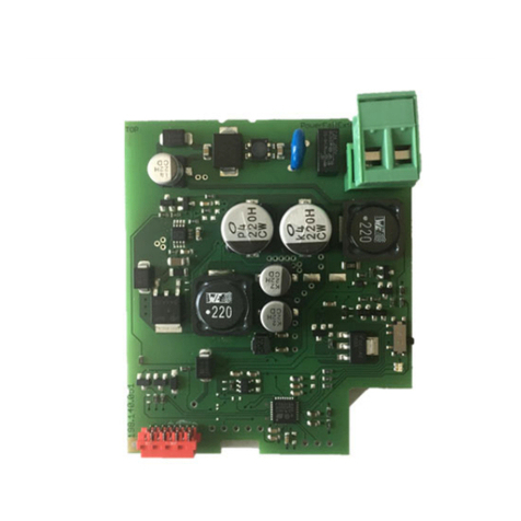
The Modbus RTU is used to upgrade Electric GF Acutators Type EA25, EA45, EA120 and EA250
with the Modbus interface. The board has to be installed into the designated slot of the
actuator. This board can be used for 24 VAC/DC as well as for 100-230 VAC actuator versions.
The connection with the customer provided PLC will be realized via two M12 plugs.
2 About this document
This document contains all the necessary information to assemble, commission or maintain
the product.
2.1 Warnings
In this instruction manual, warnings are used, which shall warn you of death, injuries or mate-
rial damage. Always read and observe these warnings!
CAUTION!
Dangerous situation!
Non-observance may result in minor injuries.
►Measures to avoid the danger.
2.2 Further symbols and labels
Symbol Meaning
1. Call for action in a certain order: Here, you have to do something.
►Call for action: Here, you have to do something.
2.3 Other applicable documents
• Planning Fundamentals GF Piping Systems
• Operating Instructions for Electric Actuators EA25-250: MA_00023_Electric_Actuator_
EA25-EA250_UL
These document can be obtained through the GF Piping Systems representative or at www.
gfps.com.
2.4 Abbreviations
Abbreviation Meaning
RTU Remote Terminal Unit
PLC Programmable Logic Controller
DCS Distributed Control System
HMI Human Machine Interface

5
Instruction manual
3 Safety information
3.1 Indended use
►Only use the product for the intended purpose, see chapter Intended use.
3.2 Users and training
• Product and accessories only to be operated by persons, who have the necessary training, knowledge or experience.
• Regularly instruct personnel on all questions regarding the local regulations applying to occupational safety and environmen-
tal protection, especially for pressurized pipelines.
• Make sure that personnel know, understand and follow the instruction manual and the instructions contained therein.
The following target groups are addressed in this instruction manual:
• Operators: Operators are instructed in the operation of the actuator and observe the safety guidelines.
• Service sta: The service sta have been professionally trained and carry out maintenance work.
• Electrically qualified person: Persons who work on the electrical equipment must be technically trained and qualified.
3.3 Precautions
►Observe the related instruction manuals. They are an integral component of this manual.
►Take precautions against electrostatic hazards.
►Do not use the product if it is damaged or faulty. Sort out the product immediately or obtain service if damaged.
►Location: Only install this products out of reach for unqualified persons. Also ensure it cannot be hit by any moving objects.
3.4 Transport and Storage
The product must be handled, transported and stored with care. Please note the following points:
►Protect the product against external forces during transport (impacts, knocks, vibrations, etc.).
►Transport and/or store the product in its unopened original packaging.
►Protect the product from heat (humidity), dust, dirt, moisture as well as heat and ultraviolet radiation.
►Ensure that the product is not damaged either by mechanical or thermal influences.
►Before assembly, check the product for damage during transport.
►Prior to installation, the product should be inspected for transport damages. Damaged products must not be installed.
3.5 Disposal
►Before disposal, separate the individual materials into recyclable materials, normal waste and hazardous waste.
►When disposing of or recycling the product, individual components and packaging, comply with local laws and regulations.
►Observe country-specific regulations, standards and guidelines.
CAUTION!
Parts of the product may be contaminated with media harmful to health and the environment, so simple cleaning is not su-
cient!
Risk of personal injury or environmental damage from these media.
Before disposing of the product:
►Collect leaking media and dispose of in accordance with local regulations. Consult safety data sheet.
►Neutralise any media residues in the product.
►Separate materials (plastics, metals, etc.) and dispose of them in accordance with local regulations.
A product marked with this symbol must be disposed of in the separate collection of electrical and electronic equipment. If you
have any questions regarding the disposal of the product, please contact your national GF Piping Systems representative.

6
Instruction manual
4 Modbus RTU board installation
CAUTION!
Danger due to energized actuator!
Injuries due to electric shock or moving parts while open actuator case.
►Disconnect the actuator from the power supply!
CAUTION!
Caution when handling the board!
Electrostatic discharge can damage the components.
►Do not touch the conductive parts of the board.
Step Process Picture
1 Disconnect the actuator from the power supply.
2 Remove the electric actuators housing cover by loosen the 4 Torx
screws.
3 Remove the plug cover on the right side.
Mount the delivered cable union together with the flat gasket at this
place.

7
Instruction manual
4 Place the Modbus RTU board into the free slot. Make sure that the
board is correctly snapped into the guide rails.
CAUTION
STATIC DISSIPATIVE
OBSERVE PRECAUTIONIS
FOR HANDLING
ELECTROSTATIC SENSITIVE
DEVICES
5 Insert the Modbus RTU connection cable into the cable union and
connect the glands D0, D1 and COM to the connector on the board.
The cable has to be secured against movement with the safety cap
fastenings.
Cable specification
Solid wire 26-16 AWG / 0.129-1.31 mm2
Stranded wire 26-16 AWG / 0.129-1.31 mm2
Torque 3.0 Lb-In / 0.34 Nm
Wire stripe length 6-7 mm
COM D0 D1
COM D0 D1
COM D0 D1
6Set the termination-switch, located at the Modbus RTU board, to ON
• for the last actuator in the Modbus network or
• if there is only one actuator in the network
to activate the end termination.
ON
ON
OFF
7 Close the housing cover of the electric actuator by fixing the 4 Torx
screws.
Reconnect the power supply to power up.

8
Instruction manual
5 Modbus RTU interface description
5.1 Introduction
Modbus is a master-slave system, where the master communicates with one or multiple
slaves. The master typically is a PLC (Programmable Logic Controller), DCS (Distributed Control
System), HMI (Human Machine Interface), RTU (Remote Terminal Unit) or PC.
The Modbus RTU interface board fits into the option slot 1 (X6) of the EA25-250 and EAMT25-
100 baseboards. It supports the Modbus RTU protocol via 2 wire RS-485 serial communication
standard. The Modbus board performs the tasks of RS-485 interface, actuator data conversion
and the issuing of actuator commands. A Modbus RTU master may command an actuator fitted
with the Modbus board to open, stop, close etc. Full list of functions, see chapter Modbus Regis-
ter Map.
You need physical access to the baseboard and Modbus board only for:
• Installing the Modbus board on the actuators baseboard and wire the RS-485 cables
• Setting of the termination switch S1 on the Modbus board
• Resetting the EA baseboard and Modbus board to factory defaults
• Viewing the diagnosis LEDs on the Modbus board or failure codes on the 7-segment
display located on EA baseboard
All other adjustments to the settings for the Modbus board may be made remotely via the
RS-485 and the Modbus RTU protocol.
5.2 Supported Function Codes
Command Function code
Read holding/ analog output registers 03
Read input registers (2 Bytes per register) 04
Write single register (2 Bytes) 06
Write multiple registers 16
5.3 Slave Address
The slave address is changeable via Modbus RTU in the Range 1…247 (see 7.2).
Slave address 1 is the default address after factory reset.
Slave address setting 0 is not allowed.

9
Instruction manual
5.4 Modbus Register Map
This chapter describes the format of the data contained in the supported Modbus messages.
5.4.1 Registers used during normal operation
Parameter No. Address (hex) Reg. Size Read/Write Unit Type Description
TYPVLT 0 0x0000 1 RD - UINT8 Type and voltage info
POSACT 1 0x0001 1 RD % UINT8 Actual position
STATE 2 0x0002 1 RD - UINT8 State flags
CURRENT 3 0x0003 1 RD mA UINT16 Absolute motor current
TEMP 4 0x0004 1 RD °C SINT8 PCB temperature
CYCLES 5 0x0005 2 RD - UINT32 Absolute number of cycles
ERRFLAGS 6 0x0007 2 RD - UINT32 Error flags
EACON 7 0x0009 1 RD/WR - UINT8 Electric Actuator Control Byte
ACKRST 8 0x000A 1 RD/WR - UINT8 ACK-Reset-Bits Control Byte
POSSET 9 0x000B 1 RD/WR % UINT8 Position setpoint in percent
BCDSET 10 0x000C 1 RD/WR - UINT16 Settings for cycle time extension, cycle time
monitoring and current monitoring
NSIGACT 11 0x000D 1 RD/WR - UINT8 Action on loss of signal
NSIGWDG 12 0x000E 1 RD/WR - UINT16 Loss of signal watchdog time
Remarks:
BCDSET, NSIGACT and NSIGWDG register settings are stored nonvolatile. This means: After
changing one of these registers, a Power-On-Reset of the actuator is required before these
changes take eect.
Register # 40001 refers to register holding register address 0x0000.
5.4.2 TYPVLT
TYPVLT byte contains information about electric actuator type and voltage variant.
It does not change during normal operation.
Byte-Name: TYPVLT
Bit 7 Bit 6 Bit 5 Bit 4 Bit 3 Bit 2 Bit 1 Bit 0
<ea_voltage> <ea_type>
<ea_type>
0 = EA25
1 = EA45
2 = EA120
3 = EA250
4 = EA15
8 = EAMT25
9 = EAMT50
10 = EAMT80
11 = EAMT100
12 = EAMT15
13 = EAMT80B
14 = EAMT100B
<ea_voltage>
0 = 24VDC / 24VAC
1 = 230VAC

10
Instruction manual
5.4.3 POSACT
Byte-Name: POSACT
Bit 7 Bit 6 Bit 5 Bit 4 Bit 3 Bit 2 Bit 1 Bit 0
<position_actual_value>
range = 0…100%
0 = position_closed
100 = position_open
255= position_invalid
5.4.4 STATE
Byte-Name: STATE
Bit 7 Bit 6 Bit 5 Bit 4 Bit 3 Bit 2 Bit 1 Bit 0
reserved reserved ready_relay teachin_acti-
ve
actuator_mo-
ving
limit_switch_
middle
limit_switch_
open
limit_switch_
closed
5.4.5 CURRENT
The CURRENT word holds the absolute value of motor current in milliamps.
Word-Name: CURRENT
15 14 13 12 11 10 9 8 7 6 5 4 3 2 1 0
<motor_current>
<motor_current>
Absolute value of motor current in milliamps.
5.4.6 TEMP
Temperature measured on EA-Baseboard.
Byte-Name: TEMP
Bit 7 Bit 6 Bit 5 Bit 4 Bit 3 Bit 2 Bit 1 Bit 0
<temperature_base>
<temperature_base>
Temperature in DEG-Celsius (-20…100°C).
5.4.7 CYCLES
The CYCLES double world holds the absolute cycles of the EA.
Label: CYCLES
High Word Low Word
Reg.# 40007 (Adr. 6) Reg.# 4000 (Adr. 5)
Double-Word = 32Bit-Value.
<cycle_counter>
Number of movement cycles since last “cycle_counter_reset”

11
Instruction manual
5.4.8 ERRFLAGS
Label: ERRFLAGS
High Word Low Word
Reg.# 40009 (Adr. 8) Reg.# 40008 (Adr. 7)
Double-Word = 32Bit-Value.
<error_flags>
0 means no error/warning asserted.
Else:
Bit Name Description
0 undervoltage Undervoltage condition / seven segment 'U'
1 over_temp_case Over temperature inside EA / seven segment 'O'
2 max_positioning_time Time monitoring / seven segment ‘S’
3 heating Heating defect / seven segment ‘H’
4 position_detection_failed Position learn required / seven segment 'e'
5 position_out_of_range Position out of range: The actual measured actuator position is outside position out
of range / seven segment ‘P’
6 manual_actuation manual actuation via handle detected / seven segment 'E'
7 accessory_no_reply accessory option board no answer / communication timed out / seven segment '9'
8 powerfail_action Powerfail board is in active state
9 powerfail_accu_lvl_warn power fail intern accu level warning / seven segment ‘L’
10 powerfail_accu_defect power fail intern accu defect error / seven segment ‘A’
11 watchdog_recovery Restart of EA through watchdog timer warning.
12 Motor current overflow max motor current monitoring tripped / seven segment 'I' (max_current_supervisor)
13 mot_driver_overload error mot driver / seven segment 'b'
14 - 31 reserved
5.4.9 EACON
Electric Actuator Control Byte
Byte-Name: EACON
Bit 7 Bit 6 Bit 5 Bit 4 Bit 3 Bit 2 Bit 1 Bit 0 Action
reserved reserved reserved positioner
enabled
stop middle open close
X X X 0 X 0 0 0 STOP
X X X 0 X X X 1 CLOSE
X X X 0 X X 1 0 OPEN
X X X 0 X 1 0 0 MIDDLE
X X X 1 X X X X POSITIO-
NER_MODE
Close is dominant as it is in operation with setpoint via power input terminals.

12
Instruction manual
5.4.10 ACKRST
Control Byte to acknowledge error and reset cycle counter.
Byte-Name: ACKRST
Bit 7 Bit 6 Bit 5 Bit 4 Bit 3 Bit 2 Bit 1 Bit 0 Action
reserved reserved reserved reserved reserved reserved cycle_
cntr_reset
error_ack
X X X X X X 1 X reset_cycle_counter
X X X X X X X 1 error_ack
5.4.11 POSSET
The position setpoint is active if positioner mode is enabled, see register EACON.
Byte-Name: POSSET
Bit 7 Bit 6 Bit 5 Bit 4 Bit 3 Bit 2 Bit 1 Bit 0 Action
position_setpoint in percent 0…100%
active if positioner is enabled
0…100 = setpoint range
0 = closed position
100 = open position
101…255 = invalid value (no action)
5.4.12 BCDSET
This setting reproduces the functionality of the monitoring board hardware.
Note that the Bytes BCDSET0 and BCDSET1 are combined to the 16-Bit-Register BCDSET.
Word-Name: BCDSET
High Byte Low Byte
BCDSET1 BCDSET0
The default value after factory reset is 0940(hex) respectively 2368.

13
Instruction manual
5.4.13 BCDSET0
Cycle time extension and cycle time monitoring.
Byte-Name: BCDSET0
Bit 7 Bit 6 Bit 5 Bit 4 Bit 3 Bit 2 Bit 1 Bit 0
<cyc_time_mon_bcd> <cyc_time_ext_bcd>
<cyc_time_ext_bcd>
Min: 0
Max: 9
Default: 0
Description:
Extents the time for a movement of typical 90°.
Positioning speed can be reduced with this setting.
This setting is dependent on EA-type – same as setting on monitoring board.
<cyc_time_mon_bcd>
Min: 0
Max: 9
Default: 4
Description:
Set threshold time for maximum accepted positioning time until target position is reached.
This setting is dependent on EA-type – same as setting on monitoring board.
5.4.14 BCDSET1
The Bit numbering refers to the BCDSET1-Byte since this is the High Byte of the 16-Bit-
BCDSET-Register. The corresponding bit numbers in BCDSET-Register are from 8 to 15.
The lower nibble of BCDSET1 contains the setting for the current monitoring functionality.
The high nibble is reserved for future use.
Byte-Name: BCDSET1
Bit 7 Bit 6 Bit 5 Bit 4 Bit 3 Bit 2 Bit 1 Bit 0
reserved <current_mon_bcd>
<current_mon_bcd>
Min: 0
Max: 9
Default: 9
Description:
Set threshold current for the current monitoring feature.
This setting is dependent on EA-type – same as setting on monitoring board.

14
Instruction manual
5.4.15 NSIGACT
Action on loss of signal (setup of busfault reaction).
Byte-Name: NSIGACT
Bit 7 Bit 6 Bit 5 Bit 4 Bit 3 Bit 2 Bit 1 Bit 0
reserved reserved reserved reserved reserved reserved < signal_loss_action>
<signal_loss_action>
Value Action / Description
0 STOP / EA stops.
1 CLOSE / EA moves to CLOSE-Position.
2 OPEN / EA moves to OPEN-Position.
3 reserved
If the MODBUS-signal is lost the EA performs the selected “signal_loss_action”.
5.4.16 NSIGWDG
It is possible to configure a maximal time without telegrams from the master before the
Modbus board triggers the configured signal loss action (busfault reaction). By default no
timeout is set.
Register NSIGWDG holds the signal loss watchdog time in milliseconds.
0 = Watchdog disabled (default setting)
1 ... 65535 = 1ms ... 65535ms
If the Modbus board is not addressed with telegrams from Modbus master for this time the
watchdog triggers and the signal loss action is executed (see NSIGACT).

15
Instruction manual
5.5 Modbus board configuration
Parameter No. Address(hex) Reg. Size Read/Write Default Type Description
SLAVE_ADR 0 0x2328 1 RD/WR 1 UINT8 1-247
BAUDRATE 1 0x2329 1 RD/WR 6 UINT8 0 = 300 baud
1 = 600 baud
2 = 1200 baud
3 = 2400 baud
4 = 4800 baud
5 = 9600 baud
6 = 19200 baud
7 = 38400 baud
8 = 57600 baud
9 = 115200 baud
DATABITS 2 0x232A 1 RD 8 UINT8 8 = 8 Data Bits
PARITY 3 0x232B 1 RD/WR 1 UINT8 0 = PAR_NONE
1 = PAR_EVEN
2 = PAR_ODD
STOPBIT 4 0x232C 1 RD/WR 1 UINT8 1 = STOP_1
2 = STOP_2
Remarks:
Changing of a parameter is only possible if the new value is in the allowed range (see descrip-
tion). These registers are non-volatile. For the new settings to become eective a reset
(Power-cycle the EA) is required.
Note the address gap between the board configuration registers and normal operation
registers.
Register # 49001 refers to register holding register address 9000 (2328(hex)).
The Modbus RTU board configuration can be reset to its default values (see Table above) by
triggering a factory reset on the Electric Actuator base-board (see user manual of the Electric
Actuator).

The information and technical data (altogether “Data”) herein are not binding, unless explicitly confirmed in writing.
The Data neither constitutes any expressed, implied or warranted characteristics, nor guaranteed properties or a guaranteed
durability. All Data is subject to modification. The General Terms and Conditions of Sale of Georg Fischer Piping Systems apply.
GF Piping Systems
Worldwide at home
Our sales companies and representatives ensure
local customer support in more than 100 countries.
www.gfps.com
Argentina / Southern South America
Georg Fischer Central Plastics Sudamérica S.R.L.
Buenos Aires / Argentina
Phone +54 11 4512 02 90
gfcentral.ps.ar@georgfischer.com
www.gfps.com/ar
Australia
George Fischer Pty Ltd
Riverwood NSW 2210
Phone +61 (0) 2 9502 8000
australia.ps@georgfischer.com
www.gfps.com/au
Austria
Georg Fischer Rohrleitungssysteme GmbH
3130 Herzogenburg
Phone +43 (0) 2782 856 43-0
austria.ps@georgfischer.com
www.gfps.com/at
Belgium / Luxembourg
Georg Fischer NV/SA
1600 Sint-Pieters-Leeuw / Belgium
Phone +32 (0) 2 556 40 20
Fax +32 (0) 2 524 34 26
be.ps@georgfischer.com
www.gfps.com/be
Brazil
Georg Fischer Sist. de Tub. Ltda.
04571-020 São Paulo/SP
Phone +55 (0) 11 5525 1311
br.ps@georgfischer.com
www.gfps.com/br
Canada
Georg Fischer Piping Systems Ltd
Mississauga, ON L5T 2B2
Phone +1 (905) 670 8005
Fax +1 (905) 670 8513
ca.ps@georgfischer.com
www.gfps.com/ca
China
Georg Fischer Piping Systems Ltd
Shanghai 201319
Phone +86 21 3899 3899
china.ps@georgfischer.com
www.gfps.com/cn
Denmark / Iceland
Georg Fischer A/S
2630 Taastrup / Denmark
Phone +45 (0) 70 22 19 75
info.dk.ps@georgfischer.com
www.gfps.com/dk
Finland
Georg Fischer AB
01510 Vantaa
Phone +358 (0) 9 586 58 25
Fax +358 (0) 9 586 58 29
info.fi.ps@georgfischer.com
www.gfps.com/fi
France
Georg Fischer SAS
95932 Roissy Charles de Gaulle Cedex
Phone +33 (0) 1 41 84 68 84
fr.ps@georgfischer.com
www.gfps.com/fr
Germany
Georg Fischer GmbH
73095 Albershausen
Phone +49 (0) 7161 302 0
info.de.ps@georgfischer.com
www.gfps.com/de
India
Georg Fischer Piping Systems Pvt. Ltd
400 083 Mumbai
Phone +91 22 4007 2000
Fax +91 22 4007 2020
branchoce@georgfischer.com
www.gfps.com/in
Indonesia
PT Georg Fischer Indonesia
Karawang 41371, Jawa Barat
Phone +62 267 432 044
Fax +62 267 431 857
indonesia.ps@georgfischer.com
www.gfps.com/id
Italy
Georg Fischer S.p.A.
20063 Cernusco S/N (MI)
Phone +39 02 921 861
it.ps@georgfischer.com
www.gfps.com/it
Japan
Georg Fischer Ltd
530-0003 Osaka
Phone +81 (0) 6 6341 2451
jp.ps@georgfischer.com
www.gfps.com/jp
Korea
Georg Fischer Korea Co. Ltd
Unit 2501, U-Tower
120 Heungdeok Jungang-ro
(Yeongdeok-dong)
Giheung-gu, Yongin-si, Gyeonggi-do
Phone +82 31 8017 1450
Fax +82 31 217 1454
kor.ps@georgfischer.com
www.gfps.com/kr
Malaysia
George Fischer (M) Sdn. Bhd.
41200 Klang, Selangor Darul Ehsan
Phone +60 (0) 3 3122 5585
Fax +60 (0) 3 3122 5575
my.ps@georgfischer.com
www.gfps.com/my
Mexico / Northern Latin America
Georg Fischer S.A. de C.V.
CP 66636 Apodaca, Nuevo Leon / Mexico
Phone +52 (81) 1340 8586
Fax +52 (81) 1522 8906
mx.ps@georgfischer.com
www.gfps.com/mx
Middle East
Georg Fischer Piping Systems (Switzerland) Ltd
Dubai / United Arab Emirates
Phone +971 4 289 49 60
gcc.ps@georgfischer.com
www.gfps.com/int
Netherlands
Georg Fischer N.V.
8161 PA Epe
Phone +31 (0) 578 678 222
nl.ps@georgfischer.com
www.gfps.com/nl
New Zealand
Georg Fischer Ltd
5018 Upper Hutt
Phone +04 527 9813
Fax +04 527 9834
nz.ps@georgfischer.com
www.gfps.com/nz
Norway
Georg Fischer AS
1351 Rud
Phone +47 67 18 29 00
no.ps@georgfischer.com
www.gfps.com/no
Philippines
George Fischer Pte Ltd
Representative Oce
1604 Pasig City
Phone +632 571 2365
Fax +632 571 2368
sgp.ps@georgfischer.com
www.gfps.com/sg
Poland
Georg Fischer Sp. z o.o.
05-090 Sekocin Nowy
Phone +48 (0) 22 31 31 0 50
poland.ps@georgfischer.com
www.gfps.com/pl
Romania
Georg Fischer Piping Systems (Switzerland) Ltd
020257 Bucharest - Sector 2
Phone +40 (0) 21 230 53 80
ro.ps@georgfischer.com
www.gfps.com/int
Russia
Georg Fischer Piping Systems (Switzerland) Ltd
Moscow 125040
Phone +7 495 748 11 44
ru.ps@georgfischer.com
www.gfps.com/ru
Singapore
George Fischer Pte Ltd
528 872 Singapore
Phone +65 6747 0611
Fax +65 6747 0577
sgp.ps@georgfischer.com
www.gfps.com/sg
Spain / Portugal
Georg Fischer S.A.
28046 Madrid / Spain
Phone +34 (0) 91 781 98 90
es.ps@georgfischer.com
www.gfps.com/es
Sweden
Georg Fischer AB
117 43 Stockholm
Phone +46 (0) 8 506 775 00
info.se.ps@georgfischer.com
www.gfps.com/se
Switzerland
Georg Fischer Rohrleitungssysteme (Schweiz) AG
8201 Schahausen
Phone +41 (0) 52 631 3026
ch.ps@georgfischer.com
www.gfps.com/ch
Taiwan
Georg Fischer Co. Ltd
San Chung Dist., New Taipei City
Phone +886 2 8512 2822
Fax +886 2 8512 2823
www.gfps.com/tw
United Kingdom / Ireland
George Fischer Sales Limited
Coventry, CV2 2ST / United Kingdom
Phone +44 (0) 2476 535 535
uk.ps@georgfischer.com
www.gfps.com/uk
USA / Caribbean
Georg Fischer LLC
92618 Irvine, CA / USA
Phone +1 714 731 8800
Fax +1 714 731 6201
us.ps@georgfischer.com
www.gfps.com/us
Vietnam
George Fischer Pte Ltd
Representative Oce
Ho Chi Minh City
Phone + 84 28 3948 4000
Fax + 84 28 3948 4010
sgp.ps@georgfischer.com
www.gfps.com/vn
International
Georg Fischer Piping Systems (Switzerland) Ltd
8201 Schahausen / Switzerland
Phone +41 (0) 52 631 3003
Fax +41 (0) 52 631 2893
info.export@georgfischer.com
www.gfps.com/int
170106-backcover-A4-industry.indd 1 11.09.2018 11:04:52
Table of contents
Other GF Computer Hardware manuals
Popular Computer Hardware manuals by other brands

Moxa Technologies
Moxa Technologies Industio CP-114 Series CP-114 Series Quick installation guide

Carel
Carel PCO1 0WB0 Series quick start guide

FreeDSP
FreeDSP AURORA user manual

Siemens
Siemens SIMOTION TB30 operating instructions

Aewin Technologies
Aewin Technologies AW-A793 user manual

NEC
NEC TTS 58AXPJ instruction manual