GFB WGA User manual

+61 2 9534 0099 www.gfb.com.au[email protected] facebook.com/GFBturbo instagram.com/gofastbits
GFB WGA
Part #7304
For Subaru WRX MY97-07
(TD04 turbo)

GFB WGA Introduction
The GFB WGA is designed to help optimize boost response and control by using a larger diaphragm area for
greater authority and control over the wastegate ap, and by allowing ne adjustment of the base boost
pressure via the 3 supplied springs and turnbuckle adjustment.
PLEASE NOTE:
Adjustment and/or tuning is required when installing this product, as it will result in higher boost
pressure which could damage your engine if the ECU is not tuned to suit.
GFB makes no recommendations regarding “safe” boost levels for your engine. This product is a tuning tool and
maximum boost pressure should be determined by an expert, taking into account the capabilities and
limitation of your specic engine and supporting modications.
Spring Selection
Gate Pressure (psi) 5psi Inner 7psi Middle 10psi Outer
5
7
10
12 (pre-installed)
15
17
22
If you require a different gate pressure, use the
table opposite to deter mine the most
appropriate spring combination.
Note that this table is only a guide to help your
selection – the actual boost level achieved
ultimately depends on a large number of
variables, and may differ from the gate pressure
shown in the table.
Before installation, you should first determine the minimum and maximum boost pressure that you want to
run, and your control method, and ensure the most appropriate spring combination is selected and installed in
the WGA.
Care should be taken when selecting boost pressures, and it is always best initially to err on the conservative
side, until the engine can be run on a dynamometer to ensure safety. Always consult an expert when making
boost changes, and it is recommended that the car be checked on a dyno, as high boost and/or lean air/fuel
mixtures can cause engine damage or worse, total failure.
If you are planning on having variable boost through the use of a boost controller, the range you can achieve
depends on your turbo setup. The lowest boost your car can run is determined by the spring (this is commonly
known as “gate pressure”), and boost can then be increased through the use of a boost controller.
As a rule of thumb, try to select springs so that your maximum boost is no more than double the “gate pressure”.
Whilst it is possible to increase boost beyond this, you may find that boost becomes less stable and harder to
control. This is because the boost controller must bleed most of the control pressure signal to the actuator, so
the wastegate is less able to self-correct for changes in manifold pressure. Using a stronger spring means the
controller bleeds off less of the pressure signal, giving the wastegate greater ability to regulate boost changes.
The WGA part #7304 comes with 3 springs which can be used individually or installed together to achieve
different boost levels. The 5psi and 7psi springs are pre-installed for a gate pressure of 12psi, which is suitable for
most Subaru applications with the TD04 turbo.

Changing the Springs
1. The spring force must be restrained
before attempting to remove the cap. To do this,
spin the locknut as close as possible to the body -
this will prevent the spring from extending as
you remove the cap
2. Remove all ve cap screws using a metric
3mm hex key
3. Residual friction from the diaphragm
sealing bead will hold the cap on even after the
screws have been removed. If the cap cannot be
removed by hand, it can be carefully pried off
using the at surface under the hose barb
5. Install the new springs, ensuring they are
correctly seated in the grooves at the bottom of
the body, and on the underside of the piston
4. Once the cap and diaphragm are removed,
unscrew the locknut completely to remove the piston,
rod, and springs.
6. CAUTION: during re-assembly take care not
to pinch the diaphragm as it compresses into the
body ( ). It can be helpful to apply a thin smear
of oil or spray lubricant to the outside of the
diaphragm to help it slip into the body easily.
7. E n s ure th e d i a p hr a g m i s c o r re c t l y
convoluted and the piston is centred in the
diaphragm, then press the cap/diaphragm onto the
piston using the same method of compressing the
spring as used during disassembly.
8. Re-install screws
Warranty
WARNING:
GFB recommends that only qualified motor engineers fit this product. GFB products are engineered for best
performance, however incorrect use or modification may cause damage to or reduce the longevity of the
engine/drive-train components.
GFB LIFETIME WARRANTY:
Our commitment to quality means that when we put our name to something, we are also staking our
reputation on it. That’s why we back our products with the best warranty in the business!
You should expect a lifetime of use from a well-engineered product, so if your GFB product fails as a result of
defective materials or faulty workmanship whilst you remain the original owner, we will repair or replace it
(limited only to the repair or replacement of GFB products provided they are used as intended and in
accordance with all appropriate warnings and limitations. No other warranty is expressed or implied).
If a fault occurs as a result of usage outside of the terms of the warranty, or you are not the original owner, fear
not, we can still help you. You should never need to throw a GFB product away, as spare parts are available
and won't cost the earth.
TECH SUPPORT:
We want you to get the best advice, first time. That’s why our engineers are available to answer any technical
questions you may have. Head to to get in touch.www.gfb.com.au/contact-us
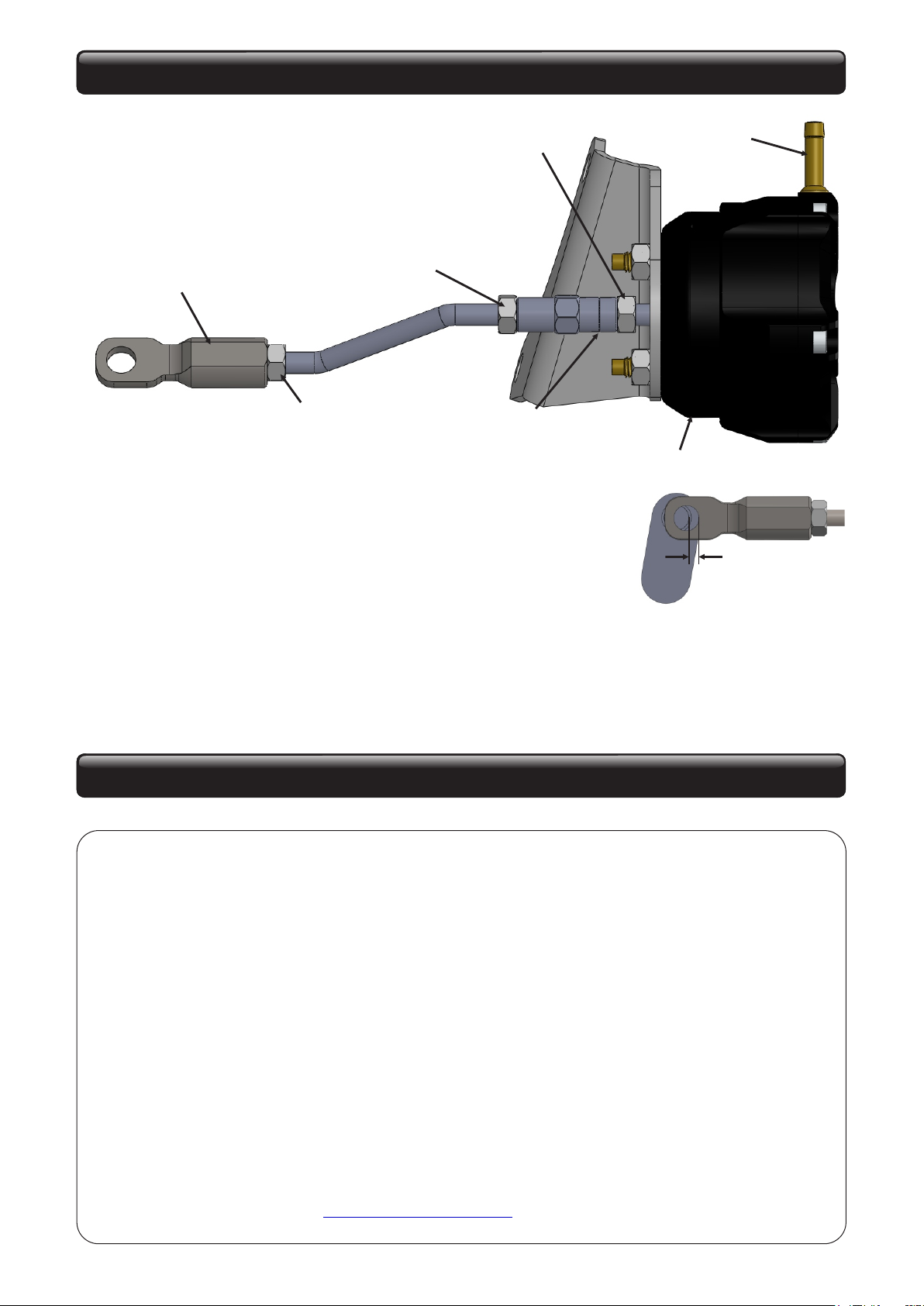
Assembly/Installation
Turnbuckle
(groove indicates
LH thread)
Turnbuckle locknut
(LH thread)
Turnbuckle locknut
(RH thread)
Clevis locknut
(RH thread)
Clevis
(RH thread)
Hose barb
Vent hole
1. Assemble WGA as shown, ensuring hose
barb points in the correct direction and the vent
hole on the WGA body faces away from possible
water ingress
2. Ensure the clevis and turnbuckle have at least 5mm of thread
engaged, but do not tighten any of the locknuts at this stage
3. Mount the WGA onto the turbo, and adjust the clevis until there is
at least 2mm of pre-load before attaching the clevis to the wastegate arm. 2mm MIN
4. Tighten all locknuts, remembering that the locknut closest to the WGA body is a left hand thread.
5. Ensure the hose barb is connected to the boost source/boost controller, then perform a boost run to
check the boost level. If boost pressure is too low, increase the pre-load via the turnbuckle (or clevis)
This manual suits for next models
1
Table of contents
Other GFB Automobile Accessories manuals


Popular Automobile Accessories manuals by other brands


curt
curt 17510 installation manual

Menabo
Menabo 000103900000 Fitting instructions

SSV Works
SSV Works TXF-OSP65 installation instructions

Whelen Engineering Company
Whelen Engineering Company Dominator D2 installation guide

Enercell
Enercell 2730696 user guide

Whelen Engineering Company
Whelen Engineering Company TIR3 Super-LED/M4 installation guide


