GFB Deceptor Pro II User manual

Deceptor Pro II (part # T9525)
Thank you for purchasing the GFB Deceptor Pro II blow off valve. We highly recommend that you familiarize
yourself with the operation and adjustments of the Deceptor Pro II before installing it.
Installing and wiring the in-car volume controller
Connect the red wire to a switched 12V power supply
inside the cabin –make sure this power supply is off
when the key is turned off, otherwise the unit will be
permanently powered.
Connect the black wire to
ground, most commonly this is
a bolt on the chassis.
Find a suitable mounting
location for the head unit. Clean
both mating surfaces with
methylated spirits or similar
cleaner and secure the
controller using the supplied
double-sided tape. Press hard
and hold the unit for 30
seconds. Note that it takes up to
24 hours for the tape to develop
a strong bond.
Plug the head unit into the
wiring harness connector.
Feed the primary servo cable
(250cm section, covered with
black mesh sleeve) through the
firewall into the engine bay.
Often there is an existing grommet that can be used for this purpose. In any case, it is important to ensure that the lead
is protected where it passes through the firewall to prevent wear or damage.
Basic Head Unit Operation
The head unit features a “sleep” mode that dims the dial lighting and reduces power to
the servo motor after approximately 10 seconds.
When the unit is “sleeping” (i.e. dim lighting), press the dial briefly to wake it up, and
then make position adjustments by rotating the dial. The unit will return to sleep mode
after 10 seconds.
WARNING: Do not attempt to manually rotate the noise adjustment, always apply power and use the
controller to change the venting bias. When testing your Deceptor Pro II, DO NOT put fingers or foreign
objects through the trumpet or plumb back ports. Doing so may result in personal injury or damage to the
blow-off valve.
Installing the blow-off valve
PLEASE NOTE!
Since the T9525 Deceptor Pro II is commonly used to replace plastic Bosch style valves, it is
important to note that in most cases the GFB valve MUST be installed in the opposite
orientation to a Bosch diverter valve.
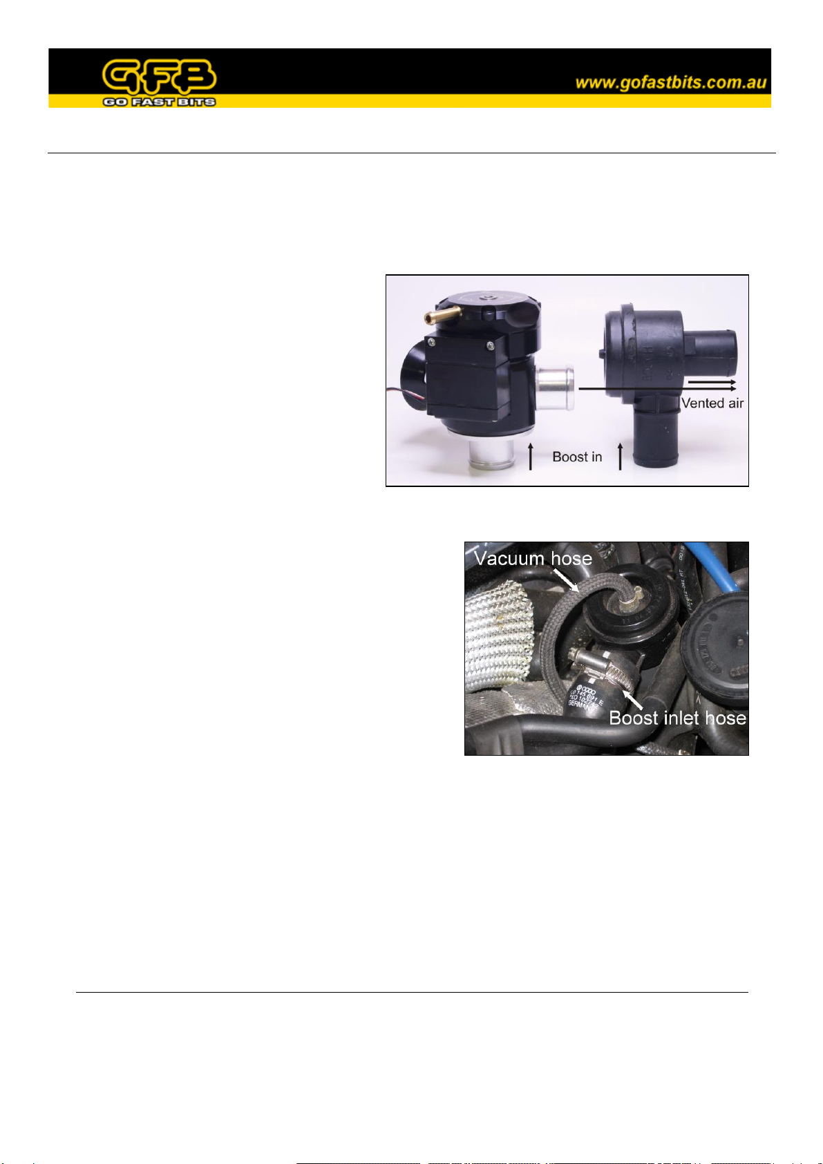
Bosch valves are typically factory installed
so that boost pressure enters the side of the
valve, and dumps through the base. The
Deceptor Pro II should be oriented so that
boost enters the base, and dumps through
the sides. THE DECEPTOR PRO II
WILL NOT OPERATE CORRECTLY
IF INSTALLED IN THE INCORRECT
ORIENTATION.
For typical Bosch diverter valve replacements (image shows a VW Golf GTI):
1. Remove any factory-fitted engine covers, and locate
the factory diverter valve. Take note of the orientation
and trace the hoses that connect to it. The bottom of
the Bosch valve is typically connected to a hose or
fitting that vents air into the turbo’s intake, whilst the
side of the valve is connected to the intercooler piping
where it receives boost pressure (see picture). If this is
the case, the Deceptor Pro II must be installed in the
reverse orientation.
2. Some cars have crimp-type hose fittings on the
diverter valve (can be seen on the vacuum hose in the
picture above), which cannot be re-used once
removed. If your car has these clamps, make sure you
have suitable replacements on hand for the installation.
3. Remove the 2 large and one small hose clamps from the factory diverter valve, then pull the valve free
from the hoses.
4. Check the location of the small vacuum hose that attaches to the top of the diverter valve. Take note of
the orientation of the vacuum nipple on the Deceptor Pro II to determine if it points in the right
direction. If not, the cap can be removed and re-fitted in any one of 4 positions for a better fit.
5. Fit the Deceptor Pro II into the factory hoses in the correct orientation, and tighten the hose clamps.
Alternative Adaptors Available
Base (inlet) adaptors:
5320 –20mm hose inlet
5330 –30mm hose inlet
5333 –33mm hose inlet
5335 –35mm hose/1” pipe mount base
5338 –38mm (1.5”) pipe mount base
5350 –HKS style mount
Recirc (outlet) adaptors:
5220 –20mm
5230 –30mm
5233 –33mm
5238 –38mm
Adjusting the spring pre-load
Contrary to popular belief, the spring pre-load DOES NOT need to be adjusted to suit different boost levels. Unlike
other valve types on the market, the Deceptor Pro II will stay shut under full throttle conditions regardless of
boost pressure or spring pre-load.
The spring pre-load affects how easily the valve opens when
you lift off the throttle, and how long it stays open when it
vents.
Note that there is no substitute for experimentation with the
spring setting, because different cars in different climates and
with different mods will unsurprisingly respond differently.
Do NOT be afraid to experiment to find the optimum setting,
you can’t hurt the engine or turbo by doing so. The guide
below will walk you through the steps involved.
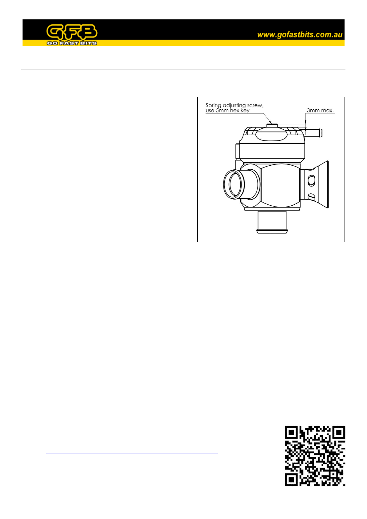
The screw in the centre of the head is the spring pre-load
adjuster - use the supplied 5mm hex key for this screw.
The softest spring setting is achieved when the top of the
adjustment screw is 3mm above the head of the valve. Do not
set the screw more than 3mm above the head.
Set the spring to the softest setting, and set the volume control to at least 50% atmosphere venting so you can
see the piston through the trumpet
Start the car and let it warm up to normal operating temperature. Make sure the A/C is off
Look at the piston through the trumpet. If it is hovering open, wind the adjustment screw in the “+” direction
until the piston closes fully. If it is already closed, proceed to the next step
Give the engine a good hard rev and snap the throttle shut quickly. The piston should lift and vent, then close
slowly and smoothly. The harder you stab the throttle, the further the piston will open (note: it will only open
fully when driving, as the turbo does not generate boost until the engine is under load). WARNING: Keep
your face away from the trumpet opening when revving the engine. View the piston from an angle away from
the blast of air
If the piston stays open too long, and is not closed when the revs drop back to idle, the engine will “stumble”,
or the revs will dip below idle. If this happens, wind the adjustment screw in the “+” direction one turn at a
time until the engine returns smoothly to idle after revving
For the final fine-tune, take the car for a drive. Watch the tacho as you pull up to a stop - if the revs dip below
idle, tighten the spring 1-2 turns
If a loud flutter is heard when lifting off sharply from full boost, wind the adjustment screw in the “-“
direction one turn at a time until the noise disappears. Note that it is not uncommon to hear a slight fluttering
at low RPM under certain conditions. This is a result of the different way in which this valve operates
compared to the factory unit, and is perfectly normal
A video example of setting up the spring pre-load can be seen by scanning the QR code, or
visiting: http://www.gfb.com.au/downloads/gfb-tv?video=KgGRfR6jt-c
NOTE: There is usually a range of around 4-5 turns within which your valve will operate
properly, and if it is outside this range it will be immediately noticeable in the symptoms
described above. If you notice none of the symptoms mentioned above, then simply leave it
where it is.

Using the In-Car Head Unit
When powered up the dial backlight will glow bright red, and will then automatically dim 10 seconds later to reduce
unnecessary glare, and will also reduce power to the motor –this is the “sleep” mode. To wake the unit up, simply
press the dial briefly before making adjustments.
The position of the dial is directly proportional the venting bias - turning the dial fully anti-clockwise sets the valve to
100% recirc, fully clockwise results in 100% atmosphere venting, and any ratio is possible between these limits.
The head unit also has a range limiting feature. This can be used to limit the maximum atmosphere-venting bias of the
Deceptor Pro II. For example, if you prefer that the maximum atmosphere venting bias is 60%, you can program the
controller so that full travel on the dial gives you only 60% movement at the valve. This is particularly useful on cars
that, through experimentation, find that full atmosphere venting does not agree with them.
To use this feature, set the dial in a position that you want as your maximum atmosphere-venting limit, then press and
hold the dial until the lights flash. The unit will record this new position as the maximum atmosphere-venting limit.
Now when you turn the dial fully clockwise, the Deceptor Pro II will only open as far as the point which you have just
set. For example, if you pushed the button with the dial set in the middle (50% atmosphere venting), full travel of the
dial will now move the valve from full recirc to 50% atmosphere-venting only.
Every time the button is pushed, the position of the dial will determine the maximum venting bias of your Deceptor
Pro. So to re-set the range to maximum again, simply turn the dial fully clockwise, then press and hold the dial.
Maintenance
All GFB valves are designed to be as maintenance free as possible. In most cars the small amount of crankcase and
rocker-cover blow-by oil that is directed into the intake system is enough to keep the piston well lubricated. However,
in some cases oil deposits or dirt can dry out and create a build-up on the piston that causes erratic operation or
sticking. If you notice a grey film on the piston or erratic venting behavior, it is a good idea to clean the valve.
This is best done with the valve removed from the car. Flush out the piston with a penetrating spray such as WD40,
whilst working the piston up and down. Using a rag, wipe off as much of the grime and build-up as possible. Re-
lubricate the valve by applying a small amount of engine oil to the piston through the side outlets and the underside of
the valve, and working the piston up and down by hand. It is a good idea to keep the trumpet area clean and free from
oil, as it attracts dirt which can result in damage to the piston.
Customer Support
GFB’s engineers are always available to help with any enquiries or issues you may have with the installation or use of
Within Australia: 02 9534 0099
International: +612 9534 0099
This product is intended for racing use only, and it is the owner’s responsibility to be aware of the legalities of fitting
this product in his or her state/territory regarding noise, emissions and vehicle modifications.
GFB products are engineered for best performance, however incorrect use or modification of factory systems may
cause damage to or reduce the longevity of the engine/drivetrain components.
GFB recommends that only qualified motor engineers fit this product. Warranty is for the period of one year from the
date of purchase and is limited only to the repair or replacement of GFB products provided they are used as intended
and in accordance with all appropriate warnings and limitations. No other warranty is expressed or implied.
This manual suits for next models
1
Table of contents
Other GFB Automobile Accessories manuals


