GH Solar GHxxxP-36 Series User manual

INSTALLATION MANUAL FOR
SOLAR PV SYSTEM
GH SOLAR
SOLAR MODULES

Photovoltaic Module User Manual
1.General information................................................................................................................... 3
1.1. Overview..........................................................................................................................3
1.2. Warning............................................................................................................................3
1.3. Safety Precautions:........................................................................................................3
1.4. Module Application Class-Class A:...........................................................................4
2.General Installation:................................................................................................................4
3.Mechanical Installation..............................................................................................................5
3.1. Mechanical Installation introduction............................................................................5
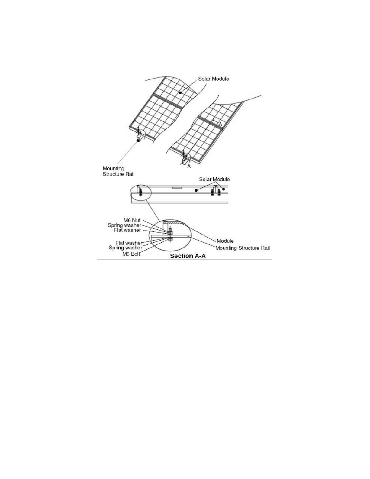
3.1.1. Screw fitting........................................................................................................ 6
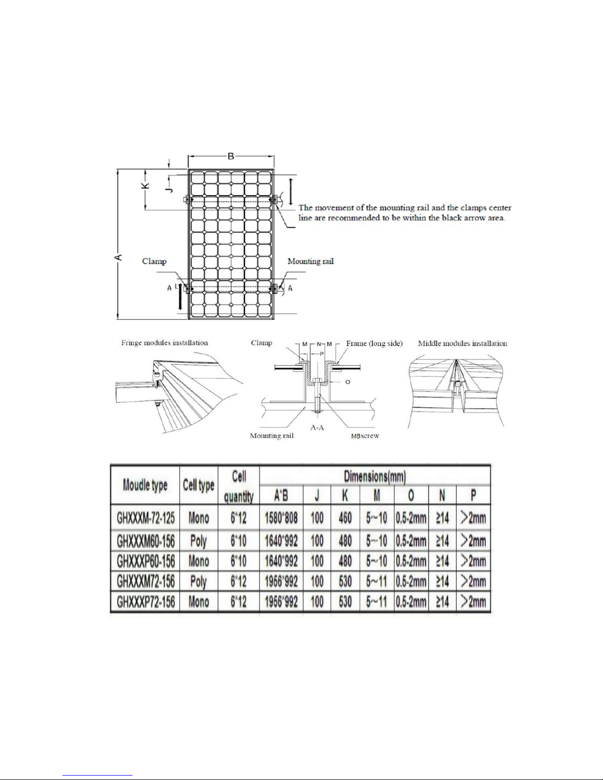
3.1.2. Independent installation of Z-type clamp single module.............................7
3.2. Site selection................................................................................................................ 10
3.2.1. Ground mounting:............................................................................................10
3.2.2. Roof mounting:.................................................................................................10
3.2.3. Pole mounting:................................................................................................. 10
3.3. Attention:....................................................................................................................... 10
4.Electrical Installation................................................................................................................11
4.1. Grid-connected electrical system:.............................................................................11
4.2. Installation conditions:.................................................................................................11
5.Grounding..................................................................................................................................12
6.Modules’ Electrical parameter as below:............................................................................. 13
6.1. GHxxxP-36 (140-160W)............................................................................................. 13
6.2. GHxxxP-48 (190-220W)............................................................................................. 14
6.3. GHxxxP-54 (210-250W)............................................................................................. 15
6.4. GHxxxP-60 (230-275W)............................................................................................. 16
6.5. GHxxxP-72 (275-315W)............................................................................................. 17
6.6. GHxxxM-36 (140-165W).............................................................................................19
6.7. GHxxxM-48 (195-220W).............................................................................................20
6.8. GHxxxM-54 (215-250W).............................................................................................21
6.9. GHxxxM-60 (235-275W).............................................................................................22
6.10. GHxxxM-72 (280-330W)...........................................................................................24
7.Maintenance:............................................................................................................................ 26
8.Disclaimer of liability................................................................................................................26
9.Contact us:................................................................................................................................ 27

1. General information
1.1.Overview
This guide contains information regarding the installation and safe handling of Ganghang.
Photovoltaic module (hereafter is referred to as “module”). Installers must read and
understand the guide before installation. Any questions, please contact our sales
department for further explanations.
1.2.Warning
The installer should conform to all safety precautions in the guide and local codes when
installing a module. Before installing a solar Photovoltaic system, installers should
become familiar with the mechanical and electrical requirement for such a system. Keep
this guide in a safe place for future reference (care and maintenance) and in case of sale
or disposal of the modules.
1.3.Safety Precautions:
Solar modules generate electricity as soon as they are exposed to light. One module on
its own is below the safety extra low volt level, but multiple modules connected in series
(summing the voltage) or in parallel (summing the current) represent a danger. The
following points must be observed when handling the solar modules to avoid the risk of
fire, sparking and fatal electric shock.
Keep children well away from the system while transporting and installing mechanical and
electrical components. Completely cover the module with an opaque material during
installation to keep electricity from being generated.
Do not wear metallic rings, watchbands, ear, nose, lip rings or other metallic devices while
installing or troubleshooting photovoltaic systems.
Abide with the safety regulations for all other components system, including wiring and
cables, connectors, charging inverters, storage batteries and rechargeable batteries, etc.
Use only equipment, connectors, wiring and support frames suitable for a solar electric
system.
Always use the same type of module within a particular photovoltaic system. The electrical
characteristics are within ±5 watts of the indicated values of Pmax under standard test
conditions (irradiance of 1000W/m2, AM 1.5 spectrums, and a cell temperature of 25°C
(77°F)). Artificially concentrated sunlight shall not be directed on the module or panel.
Under normal conditions, a photovoltaic module is likely to experience conditions that

produce more current and/or voltage than reported at standard test conditions. The
suggested fuse must be used for over-current protection.
Accordingly, the values of Isc and Voc marked on this module should be multiplied by a
factor of 1.25 when determining component voltage ratings, conductor capacity, fuse sizes
and size of controls connected to the PV output. Modules have passed mechanical load
test 5400Pa according to the IEC61215. To avoid exceeding the maximum load,
site-specific live loads such as wind and snow would be taken into account. Installation
shall be in accordance with local standard and conditions. Climate conditions Ambient
temperature: -20~+40℃
36pcs: The maximum number of series connection: 35;
The maximum number of parallel connection: 2;
48pcs: The maximum number of series connection: 27;
The maximum number of parallel connection: 2;
54pcs: The maximum number of series connection: 23;
The maximum number of parallel connection: 2;
60pcs: The maximum number of series connection: 21;
The maximum number of parallel connection: 2;
72pcs: The maximum number of series connection: 17;
The maximum number of parallel connection: 2;
1.4.Module Application Class-Class A:
General access, hazardous voltage, hazardous power applications Modules rated for use
in this application class may be used in systems operating at greater than 50VDC or 240W,
where general contact access is anticipated. Modules qualified for safety through
IEC61730-1 and this part of IEC61730 within this application class are considered to meet
the requirement for safety class Ⅱ.
Whenever necessary to comply with local codes, use a listed fuse or circuit breaker, rated
for the maximum series fuse rating of the module and the system voltage.
2. General Installation:
Installing solar Photovoltaic systems may require specialized skills and knowledge.
Installation should be performed only by qualified persons. Each module comes with a
permanently attached junction box. Box can provide customers with fitted cables for ease
of installation if desired.
Installers should assume the risk of all injury that might occur during installation, including,
without limitation, the risk of electric shock. Do not disconnect under load. Photovoltaic
solar modules change light energy to direct-current electrical energy. Modules may be
ground mounted, mounted on rooftops, vehicles or boats.
Proper design of support structures is responsibility of the system designers and
installers.
Do not attempt to disassemble the modules, and do not remove any attached nameplates
or components from the modules. Do not apply paint or adhesive to module top surface.

When installers installing the system, abide with all local, regional and national statutory
regulations. Obtain a building permit where necessary.
3. Mechanical Installation
3.1.Mechanical Installation introduction
The PV modules should be mounted in a location where they will receive maximum
sunlight throughout the year.
For detailed information on the best elevation tilt angle for the installation, refer to
standard solar Photovoltaic installation guides or a reputable solar installer or systems
integrator.
The module should not be shaded at any time of the daytime.
The modules are not to be installed with a slope less than 127mm/305mm.
Selecting the proper support frame.
Always observe the instructions and safety precautions included with
the support frames to be used with the modules.
Do not attempt to drill holes in the glass surface of the modules. To do so will void the
warranty.
Do not drill additional mounting holes in the frame of the modules. Doing so will void the
warranty.
The support module mounting structure must be made of durable, corrosion-resistant and
UV-resistant material.
Modules must be securely attached to the mounting structure using all eight mounting
points.

3.1.1. Screw fitting
The modules shall be secured with M8 stainless steel or equivalent bolts with washers
and nuts. The applied torque is about 8 Newton-meters.
The module frame must be attached to a mounting rail using M8 corrosion-proof screws
together with spring washers and flat washers in four symmetrical locations on the PV
module.
Applied torque should be 5~8 Newton-meters. Please find detailed mounting information
in the below Figure.

Note:
Clearance between modules frames and surface of the wall or roof is required
to prevent wiring damage and to allow air to circulate behind the module.
Recommended stand-off height is 115mm.
When mounting, be sure that the module’s drain holes are not blocked.
Please use corrosion-proof screws (M8) in the existing installing holes in the
module frame.
We recommend that the longer size of the frame should be stick to the
bracket completely. For safety, the bracket width should be wider than the
frame face which stick to the bracket. The thickness of the bracket had better
withstand the impact of external 5400pa forces.
3.1.2. Independent installation of Z-type clamp single module
The module clamps should not come into contact with the front glass and must not deform
the frame. Be sure to avoid shadowing effects from the module clamps.
The installation adopts Z-type clamp single module independent installation frame
mechanical load test includes wind load 2400PA and snow 5400PA.
The 2400 Pa test takes the inside installation hole position as benchmark, and fix clamp

transverse bar.
The 5400 Pa test takes the inside installation hole position as benchmark, and fix clamp
transverse bar.
The detailed installation method shall be seen in the following sketch:
Figure1 above: PV module installed at long side with Clamp fitting method
Table 1 above: Mechanical dimensions when modules installed at long side with Clamp
fitting method

Figure 2 above: PV module installed at short side with Clamp fitting method
Table 2 above: Mechanical dimensions when modules installed at short side with Clamp
fitting method

3.2.Site selection
3.2.1. Ground mounting:
Select the height of the mounting system to prevent the lowest edge of the module from
being covered by snow for a long time in winter in areas that experience heavy snowfalls.
In addition, assure the lowest portion of the module is placed high enough so that it is not
shaded by plants or trees or damaged by sand and stone driven by wind.
3.2.2. Roof mounting:
When installing a module on a roof or building, ensure that it is securely fastened and
cannot fall as a result of wind or snow loads. Provide adequate ventilation under a module
for cooling (200mm minimum air space between module and mounting surface). When
installing module on a roof, ensure that the roof construction is suitable.
In addition, any roof penetration required to mount the module must be properly sealed to
prevent leaks. In some cases, a special support frame may be necessary.
The roof installation of solar modules may affect the fireproofing of the house construction.
The modules are rated fire Class C. because their modules or panels are non-integral
ones, they should be mounted over a fire resistant roof.
Do not install modules on a roof or building during strong winds in case of accidents.
3.2.3. Pole mounting:
When installing a module on a pole, choose a pole and module mounting
structure that will withstand anticipated winds for the area.
Roof mounting shall comply with relevant local legislation and law.
3.3. Attention:
Do not lift the module by grasping the module’s junction box or electrical leads.
Do not stand or step on module.
Do not drop module or allow objects to fall on module. To avoid glass breakage, do not
place any heavy objects on the module.
Do not set the module down hard on any surface. Inappropriate transport and installation
may break module.

4. Electrical Installation
4.1.Grid-connected electrical system:
The DC electrical energy generated by photovoltaic systems may also be converted to AC
and connected to a utility grid system. As local utilities’ policies on connecting renewable
energy systems to their grids vary from region to region. Consult a qualified system
designer or integrator to design such a system. Permits are normally required for installing
such a system and the utility must formally approve and inspect such a system before it
can be accepted.
4.2.Installation conditions:
Typically electrical work for PV systems requires building permits. The installer is
responsible to understand the permits and codes that must be obeyed for electrical hook
up. The PV Module has a pair of male and female waterproof connectors. For a series
electrical connection, connect positive (+) connector of first PV Module to negative (-)
connector of the following Module.
Do not short the positive and the negative. Do not disconnect under load.
Be sure connectors have no gap between the insulators. In case there is a gap, a fire
and/or an electrical shock may occur.
The installer must size the array wiring so that maximum voltage drop from the module to
the inverter is less than 2%.
Do not use modules of different configurations in the same system.
Several modules are connected in series and then in parallel to form a PV array,
especially for application with a high operation voltage. If modules are connected in series,
the total voltage is equal to the sum of individual voltages.
All modules must have the same amperage in order to have optimal power output.
For applications requiring high currents, several photovoltaic modules can be connected
in parallel; the total current is equal to the sum of individual currents.
Consult your qualified installers for proper connection with array junction box.
Module is supplied with connectors to use for system electrical connections.
Consult rated local wiring regulations to determine system wire size, type, and
temperature.
For field connections, use minimum 12 AWG copper wires insulated for a minimum of
90 °C.
The junction box has a breather port. The breather port must be mounted facing down and
cannot be exposed to rain. Therefore, the junction box must be on the higher side of the
module when it is mounted.

5. Grounding
All module frames must be attached to solid ground. A qualified electrician must complete
ground connections. The grounding wire must be properly fastened to the module frame
to assure good electrical contact.
Use the recommended type, or an equivalent, connector for this wire.

Junction box type: GF20, connector type: 05-6, from Renhe Photovoltaic Technology
Co.,Ltd
6. Modules’ Electrical parameter as below:
6.1.GHxxxP-36 (140-160W)
Type Name or
Model No. :
GH140P-3
6
GH145P-3
6
GH150P-3
6
GH155P-3
6
GH160P-3
6
Maximum System
Voltage [VDC] :
1000
1000
1000
1000
1000
Maximum Power
Voltage(Vmp)
17.95
17.97
17.99
18.01
18.02
Maximum Power
Current (Imp)
7.8
8.07
8.34
8.61
8.88
Rated Maximum
Power [W]
140
145
150
155
160
Assembly
Type
Material
Number
Screw
Ф4mm
Stainless steel
1
Nut
Ф4mm
Stainless steel
1
Washer
Ф4mm
Stainless steel
3
Claw Washer
Ф4mm
Stainless steel
2
Cupule Washer
Ф4mm
Stainless steel
2
Bypass diode type
Ф4mm
Used in junction box type
2
PST4020
Ф4mm
GF20
2

Tolerance of
Rating [%] :
±3
±3
±3
±3
±3
Rated Short Circuit
Current [A] :
8.2
8.48
8.77
9.05
9.34
Rated Open Circuit
Voltage [V] :
22.47
22.49
22.51
22.53
22.54
Over-current
protection rating
[A]:
15
15
15
15
15
Application Class
(IEC 61730) :
Class A
Class A
Class A
Class A
Class A
Protection Class :
Class II
Class II
Class II
Class II
Class II
Dimensions (l x w x
h) [mm] :
1480*670*
40
1480*670*
40
1480*670*
40
1480*670*
40
1480*670*
40
Module area [m²] :
0.99
0.99
0.99
0.99
0.99
6.2.GHxxxP-48 (190-220W)
GH190P-4
8
GH195P-4
8
GH200P-4
8
GH205P-4
8
GH220P-4
8
1000
1000
1000
1000
1000
23.91
23.92
23.94
23.96
24.01
7.95
8.15
8.35
8.56
9.16
190
195
200
205
220
±3
±3
±3
±3
±3
8.71
8.94
9.16
9.38
9.56
28.69
28.71
28.73
28.76
28.82
15
15
15
15
15
Class A
Class A
Class A
Class A
Class A
Class II
Class II
Class II
Class II
Class II
1320*992*
40
1320*992*
40
1320*992*
40
1320*992*
40
1320*992*
40
1.31
1.31
1.31
1.31
1.31

6.3.GHxxxP-54 (210-250W)
Type Name or
Model No. :
GH210P-5
4
GH215P-5
4
GH220P-5
4
GH225P-5
4
GH230P-5
4
Maximum
System Voltage
[VDC] :
1000
1000
1000
1000
1000
Maximum Power
Voltage(Vmp)
28.02
28.03
28.04
28.05
28.08
Maximum Power
Current (Imp)
7.49
7.67
7.85
8.02
8.19
Rated Maximum
Power [W]
210
215
220
225
230
Tolerance of
Rating [%] :
±3
±3
±3
±3
±3
Rated Short
Circuit Current
[A] :
8.27
8.46
8.66
8.85
9.04
Rated Open
Circuit Voltage
[V] :
33.39
33.42
33.43
33.45
33.46
Over-current
protection rating
[A]:
15
15
15
15
15
Application
Class (IEC
61730) :
Class A
Class A
Class A
Class A
Class A
Protection
Class :
Class II
Class II
Class II
Class II
Class II
Dimensions (l x
w x h) [mm] :
1480*992*
40
1480*992*
40
1480*992*
40
1480*992*
40
1480*992*
40
Module area
[m²] :
1.47
1.47
1.47
1.47
1.47
Type Name or Model
No. :
GH235P-5
4
GH240P-5
4
GH245P-5
4
GH250P-5
4
Maximum System
Voltage [VDC] :
1000
1000
1000
1000
Maximum Power
Voltage(Vmp)
28.09
28.12
28.14
28.16
Maximum Power
Current (Imp)
8.37
8.53
8.71
8.88

Rated Maximum
Power [W]
235
240
245
250
Tolerance of Rating
[%] :
±3
±3
±3
±3
Rated Short Circuit
Current [A] :
9.24
9.43
9.52
9.58
Rated Open Circuit
Voltage [V] :
33.48
33.49
33.51
33.52
Over-current
protection rating [A]:
15
15
15
15
Application Class (IEC
61730) :
Class A
Class A
Class A
Class A
Protection Class :
Class II
Class II
Class II
Class II
Dimensions (l x w x h)
[mm] :
1480*992*
40
1480*992*
40
1480*992*
40
1480*992*
40
Module area [m²] :
1.47
1.47
1.47
1.47
6.4.GHxxxP-60 (230-275W)
Type Name or
Model No. :
GH230P-6
0
GH235P-6
0
GH240P-6
0
GH245P-6
0
GH250P-6
0
Maximum
System Voltage
[VDC] :
1000
1000
1000
1000
1000
Maximum Power
Voltage(Vmp)
31.11
31.13
31.15
31.18
31.19
Maximum Power
Current (Imp)
7.39
7.55
7.7
7.86
8.02
Rated Maximum
Power [W]
230
235
240
245
250
Tolerance of
Rating [%] :
±3
±3
±3
±3
±3
Rated Short
Circuit Current
[A] :
8.15
8.33
8.49
8.67
8.84
Rated Open
Circuit Voltage
[V] :
37.12
37.14
37.16
37.18
37.21
Over-current
protection rating
[A]:
15
15
15
15
15

Application
Class (IEC
61730) :
Class A
Class A
Class A
Class A
Class A
Protection
Class :
Class II
Class II
Class II
Class II
Class II
Dimensions (l x
w x h) [mm] :
1640*992*
40
1640*992*
40
1640*992*
40
1640*992*
40
1640*992*
40
Module area
[m²] :
1.63
1.63
1.63
1.63
1.63
Type Name or
Model No. :
GH255P-6
0
GH260P-6
0
GH265P-6
0
GH270P-6
0
GH275P-6
0
Maximum System
Voltage [VDC] :
1000
1000
1000
1000
1000
Maximum Power
Voltage(Vmp)
31.22
31.24
31.27
31.29
31.31
Maximum Power
Current (Imp)
8.17
8.32
8.47
8.63
8.78
Rated Maximum
Power [W]
255
260
265
270
275
Tolerance of Rating
[%] :
±3
±3
±3
±3
±3
Rated Short Circuit
Current [A] :
9.01
9.18
9.35
9.52
9.59
Rated Open Circuit
Voltage [V] :
37.23
37.26
37.29
37.31
37.32
Over-current
protection rating [A]:
15
15
15
15
15
Application Class
(IEC 61730) :
Class A
Class A
Class A
Class A
Class A
Protection Class :
Class II
Class II
Class II
Class II
Class II
Dimensions (l x w x
h) [mm] :
1640*992*
40
1640*992*
40
1640*992*
40
1640*992*
40
1640*992*
40
Module area [m²] :
1.63
1.63
1.63
1.63
1.63
6.5.GHxxxP-72 (275-315W)
Type Name or
Model No. :
GH275P-7
2
GH280P-7
2
GH285P-7
2
GH290P-7
2
GH295P-7
2

Maximum
System Voltage
[VDC] :
1000
1000
1000
1000
1000
Maximum
Power
Voltage(Vmp)
37.38
37.39
37.42
37.45
37.51
Maximum
Power Current
(Imp)
7.36
7.49
7.62
7.74
7.86
Rated
Maximum
Power [W]
275
280
285
290
295
Tolerance of
Rating [%] :
±3
±3
±3
±3
±3
Rated Short
Circuit Current
[A] :
8.13
8.27
8.41
8.56
8.7
Rated Open
Circuit Voltage
[V] :
44.53
44.55
44.58
44.59
44.65
Over-current
protection rating
[A]:
15
15
15
15
15
Application
Class (IEC
61730) :
Class A
Class A
Class A
Class A
Class A
Protection
Class :
Class II
Class II
Class II
Class II
Class II
Dimensions (l x
w x h) [mm] :
1957*992*
50
1957*992*
50
1957*992*
50
1957*992*
50
1957*992*
50
Module area
[m²] :
1.94
1.94
1.94
1.94
1.94
GH305P-7
2
GH310P-7
2
GH315P-7
2
1000
1000
1000
37.57
37.59
37.61
8.12
8.25
8.38
305
310
315
±3
±3
±3
8.98
9.23
9.34

44.69
44.71
44.73
15
15
15
Class A
Class A
Class A
Class II
Class II
Class II
1957*992*
50
1957*992*
50
1957*992*
50
1.94
1.94
1.94
6.6.GHxxxM-36 (140-165W)
Type Name
or Model No. :
GH140M-3
6
GH145M-
36
GH150M-
36
GH155M-
36
GH160M-
36
GH165M-
36
Maximum
System
Voltage
[VDC] :
1000
1000
1000
1000
1000
1000
Maximum
Power
Voltage(Vmp)
18.45V
18.53V
18.6V
18.67V
18.75V
18.82V
Maximum
Power
Current (Imp)
7.59A
7.82A
8.06A
8.3A
8.53A
8.77A
Rated
Maximum
Power [W]
140
145
150
155
160
165
Tolerance of
Rating [%] :
±3
±3
±3
±3
±3
±3
Rated Short
Circuit
Current [A] :
8.29A
8.55A
8.82A
9.08A
9.34A
9.6A
Rated Open
Circuit
Voltage [V] :
22.23V
22.31V
22.39V
22.46V
22.54V
22.62V
Over-current
protection
rating [A]:
15
15
15
15
15
15
Application
Class (IEC
61730) :
Class A
Class A
Class A
Class A
Class A
Class A

Protection
Class :
Class II
Class II
Class II
Class II
Class II
Class II
Dimensions (l
x w x h)
[mm] :
1480*670*
40
1480*670
*40
1480*670
*40
1480*670
*40
1480*670
*40
1480*670*
40
Module area
[m²] :
0.99
0.99
0.99
0.99
0.99
0.99
6.7.GHxxxM-48 (195-220W)
Type Name or
Model No. :
GH195M-
48
GH200M-
48
GH205M-
48
GH210M-
48
GH215M-
48
GH220M-
48
Maximum
System Voltage
[VDC] :
1000
1000
1000
1000
1000
1000
Maximum
Power
Voltage(Vmp)
24.71V
24.79V
24.87V
24.95V
25.02V
25.09V
Maximum
Power Current
(Imp)
7.89A
8.07A
8.24A
8.42A
8.59A
8.77A
Rated
Maximum
Power [W]
195
200
205
210
215
220
Tolerance of
Rating [%] :
±3
±3
±3
±3
±3
±3
Rated Short
Circuit Current
[A] :
8.63A
8.83A
9.02A
9.22A
9.42A
9.61A
Rated Open
Circuit Voltage
[V] :
29.73V
29.81V
29.89V
29.97V
30.04V
30.11V
Over-current
protection
rating [A]:
15
15
15
15
15
15
Application
Class (IEC
61730) :
Class A
Class A
Class A
Class A
Class A
Class A
Protection
Class :
Class II
Class II
Class II
Class II
Class II
Class II
Dimensions (l x
1320*992
1320*992
1320*992
1320*992*
1320*992*
1320*992*
This manual suits for next models
9
Table of contents
Other GH Solar Solar Panel manuals
Popular Solar Panel manuals by other brands

Wasserstein
Wasserstein Blink Doorbell Solar Panel user manual

Antaisola
Antaisola Rail IV installation manual

Conergy
Conergy PE Series installation manual

Samlexpower
Samlexpower MSK-90 owner's manual

Roofit.Solar
Roofit.Solar Double Seam installation manual

SnapNrack
SnapNrack Series 100 UL installation manual