Phono Solar PS M4H-20/UH Series User manual

Phono Solar Technology Co., Ltd.
Address : No. 1 Xinghuo Rd., Nanjing Hi-tech Zone, Nanjing, China
Tel: +86 25 5863 8000 Fax: +86 25 5863 8009
E-mail: support@phonosolar.com
Website: www.phonosolar.com
PHONO SOLAR TECHNOLOGY CO.,LTD.
Photovoltaic Module
Version: EN-IM-IEC-20210618
Copyright © PHONO SOLAR, 2021

CONTENTS
1.
IMPORTANT SAFETY GUIDE
2.
PRODUCT IDENTIFICATION
3.
MECHANICAL INSTALLATION
4.
ELECTRICAL INSTALLATION
5.
GROUNDING
6.
MAINTENANCE
7.
DISCLAIMER OF LIABILITY

Stability
/
Reliability
/
Creativity
1
IMPORTANT SAFETY GUIDE
O NOT use mirrors or
magni
fi
ers to concentrate
sunlight onto the module.
M
odul
e
(I
EC
)
Ra te d
DO NOT lift or move the
module by holding the
junction box or cable.
MMoo
duld
ul
ee
((IIE
ECC
))
DO NOT expose the back of
the module to direct
sunlight.
DO NOT drill holes in the frame.
DO NOT paint the module
or attach anything on
to the back of the module.
DO NOT place anything on
the module or press on
the module surface.
DO NOT install or handle
module in wet or strong
windy conditions.
DO NOT use module near
equipment or in places where
flammable gases may be
generated or collected.
DO NOT attempt to disassemble
the modules, and do not
remove any attached
nameplates or components from
the module.
DO NOT drop the module or
allow objects to fall on the
module.
DO NOT wear metal ornaments
while handling the module or
during the installation.
Insulated gloves must be
worn while handling the
module and during the
installation.
This manual contains information regarding product identification and the
safe installation and maintenance of photovoltaic modules (hereafter referred to
as “ module” ) supplied by PHONO SOLAR TECHNOLOGY CO., LTD. (hereafter referred
to as “PHONO
SOLAR”) .
The term “module” can be interpreted as a
single module or multiple modules depending on the context.
Installers must already be familiar with the mechanical and electrical
requirements for a photovoltaic system. Installers must also read this manual
carefully prior to installation. We recommend that you keep this manual in a
safe place for future reference and in case of future sale or disposal of the
module.
1.1
General Safety
The installation of a photovoltaic system requires specialized skills and
knowledge and must only be carried out by licensed/qualified persons.
Installers should assume all risks of injury and do everything to avoid
potential damages and risks that might occur during installation, including but
not limited to, the risks of electric shock.
PHONO SOLAR modules do not need special cables for connection. All of the
modules have permanent junction boxes, cables and connectors.
Do not use mirrors or magnifiers to concentrate sunlight onto the modules.
The modules generate DC electrical energy from sunlight. They are designed
for outdoor use and can be mounted onto frames on rooftops or in the
ground etc.
Do not paint the module or attach anything on to the back of the module.
Do not attempt to disassemble the modules, and do not remove any attached
nameplates or components from the modules.
1.2
Handling safety
When handling the module insulated gloves must be worn.
Inappropriate transportation and installation may break the
module.
Do not lift or move the module by holding the junction box
or cable.
Do not place anything on the module or press on the module
surface. Do not drop the module or allow objects to fall on the
module.
1

Stability
/
Reliability
/
Creativity
2 3
Do not expose the back of the module to direct
sunlight. Do not wear metal ornaments while handling
the module.
Do not install or handle modules in wet or strong windy conditions.
1.3
Installation safety
Local, regional and state laws and regulations must be adhered to while
installing a photovoltaic system. For example, any necessary licenses must be
obtained prior to the installation commencing. Regulations around vehicles and
ships must also be observed during the installation.
Observe all safety rules for the other system components, including the
cables, connectors, charging controllers, inverter and storage battery etc.
Do not place the modules near a location where flammable gases are either
generated or collected.
Insulated gloves must be worn during the
installation.
Do not wear metal ornaments during the
installation.
Do not drill holes in the frame.
U
nde
r
no
r
ma
l
con
di
t
i
on
s
,
a m
o
du
l
e
i
s
l
i
k
ely
t
o
p
r
o
duc
e
m
o
r
e
curre
n
t
an
d/o
r
voltage
than reported
under Standard Test
Condit
ions (STC). A
ccordi
ngly,
the
val
ues
o
f Isc and Voc marked o
n the modul
e
nameplate shou
l
d
be
multiplied
by a
fa
ctor
when
deter
mining
the component
voltage ratings,
conductor
current
ratings,
fu
se siz
es,
and the
size
of controller
s
conne
c
ted
to
the pho
t
ov
oltaic
sy
st
em.
The
exact
fa
ctor
value
shou
ld
be
suggested by a
l
icensed/qualified
perso
n.
The live connector may cause fire. spark or lethal shocks even when the
modules are not connected.
Electricity can be generated when the modules are exposed to sunlight,
even if they are not connected. It is dangerous to touch 30V DC or higher,
so never open the electrical connectors or unplug the electrical connectors
while the circuit is under load, and do not touch the live connectors
during the installation when the modules are exposed to sunlight.
Children should be kept away from the photovoltaic system.
In order to prevent current and voltage generation during installation an
opaque board can be used to cover the modules.
Only use licensed/qualified insulated tools.
The frame of the modules may be grounded according to local, regional and
state safety and electrical standards.
Only Balance of System (BOS) components that conform with local,
regional and state safety electricity standards should be used to avoid
affecting module performance and/or module damage.
1.4
Fire Safety
Consult your local authority for guidelines and requirements for building
or structural fire safety.
Roof constructions and installations may affect the fire safety of a building;
an improper installation may create a hazard in the event of a fire.
Use components such as ground fault circuit breakers and fuses as required
by the local authorities.
Do not use the modules near a location where flammable gases are either
generated or collected.
PRODUCT IDENTIFICATION
On the back of each module there are 2 labels that provide the following information:
Nameplate: Describes the product type, rated power, rated current, rated voltage, open
circuit voltage, short circuit current, all as measured under STC; weight, dimensions
etc.; the maximum system voltage of 1000V/1500V DC.
Warning: The value of Voc multiplied by the number of modules in series
should not be bigger than the maximum system voltage marked in the
nameplate.
Ba
r
c
o
d
e
:
This is used to identify each module. Each module has a unique
and traceable serial number in the form of barcode. The barcode of each
PHONO SOLAR module has 15 letter/digits.
Warning:Do not remove the nameplate or barcode.The PHONOSOLAR product
warranty will be void if either the module nameplate or barcode is removed.
2

Stability
/
Reliability
/
Creativity
4 5
MECHANICAL INSTALLATION
(Note:Allinstructionshere afterareforreferenceonly. A licensed/qualifiedperson or
installer must be responsible for the design, installation, mechanical load calculation and
security of the photovoltaic system.)
3.1
Select suitable locations for installation
Select a suitable location for installing the modules.
PHONO SOLAR recommends that to achieve the best performance the modules
should face south in northern latitudes and north in southern latitudes. The
exact tilt angle and orientation of mounted modules should be recommended by a
licensed/ qualified installer.
The modules should be completely free of shade at all times.
Do not place the modules near a location where flammable gases are either
generated or collected.
Note1: Saline environments can accelerate the processes of electrical insulation
losses and galvanic corrosion, especially when different metals with high
electrochemical potential come into contact each other.
In saline environments, based on the distance to seashore, Phono
Solar generally
classifies coastal PV installation into three different levels:
From 0 up to 50 meters, Phono Solar does not recommend any installation due
to concerns for salt-mist corrosion.
From 50 to 500 meters, Phono Solar regards this as “Near -Coast”
installation requiring adherence to salt-mist corrosion prevention.
From 500 meters and onwards, Phono Solar estimates the risk of salt mist
corrosion is minor and only requires annual preventive maintenance.
In “Near- Coast” installation, Phono Solar PV modules must be installed
under the following conditions:
During the installation, do not scratch or break the corrosion-resistant
coating (e.g.
electroplated layer, oxidized coating, etc.) on the modules and mounting
systems.
Phono solar recommends that the modules shall be mounted with a minimum tilt
angle of 10° in respect to the horizen , or follow the recommendations of
experienced PV module installers.
Use corrosion-resistant materials (e.g. stainless steel SUS 316) for
components (nut,
bolt, gasket, etc.) to fixing the modules and mounting systems.
To avoid possible galvanic corrosion between the aluminum frame and the
support structure, mica lamination, or other silicone, or fluoride made
gasket shall be interposed between the two metals
When grounding the module frames, stainless steel hardware must also
be used. To prevent salt corrosion to grounding block, fluorocarbon varnish
could be sprayed on the grounding block thoroughly to form an anti-corrosion
coating (at least 40um thick) or a pad of butyl plaster covering could be
placed on the grounding block completely.
To ensure optimum module performance for near-coast installation, a
system maintenance service of every three months is generally recommended and
additionally the following maintenance measures shall be taken:
Check the frame, mounting system, grounding block and other junction areas
for potential signs of corrosion.
Clean the frame, mounting system, grounding block and other junction
areas from salt and dust accumulation.
To repair the rusty areas, apply butyl plaster or fluorocarbon varnish
spray to cover the area thoroughly after clean the salt and other dust
accumulations around the rusty areas.
Note2 :In environments where ammonia is present, Phono Solar PV modules must be
installed under the following conditions:
When fixing the modules using the 8 mounting slots, all the hardware (washers,
screws and nuts) shall be made of stainless steel;
To avoid possible galvanic corrosion between the aluminum frame and the support
structure, PVC washers or neoprene tape shall be interposed between the two metals;
When grounding the module frames, stainless steel hardware must also be used.
Note3 :If you are planning to use the PV modules where the water damage
(Humidity: > 85RH%) may be possible, please consult with Phono Solar technical
support first to determine an appropriate installation method and module type ,
or to determine whether the installation is possible.
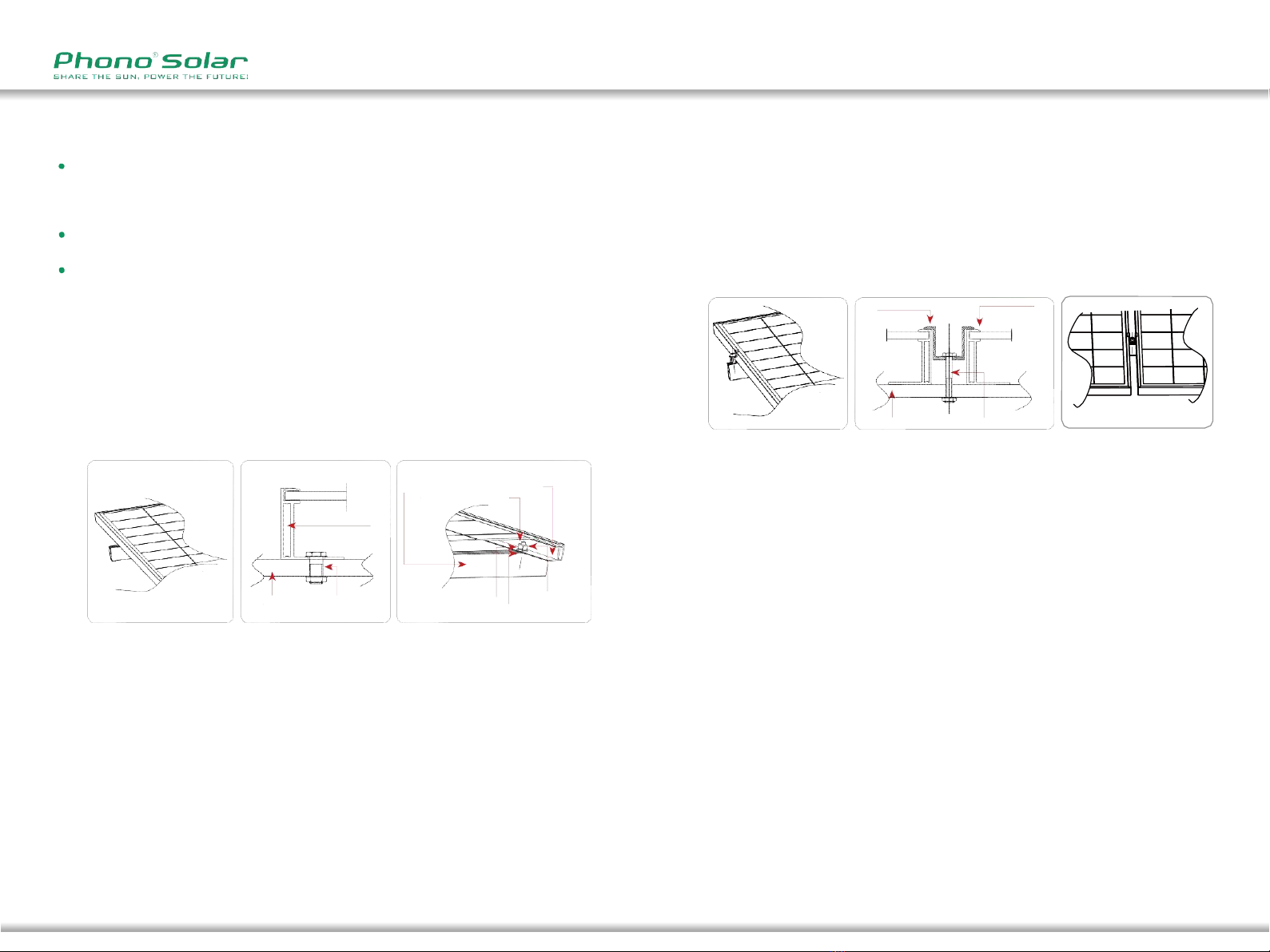
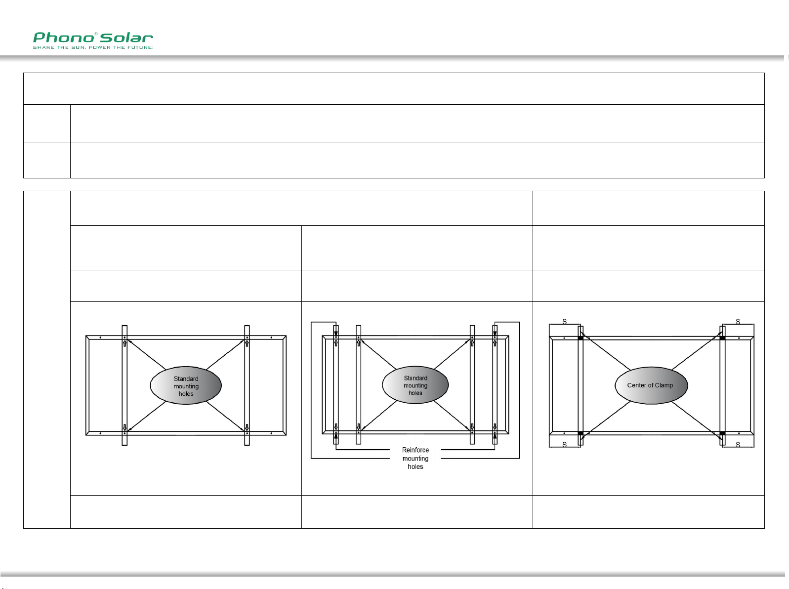
3.2
Select suitable mountingrails
Please observe the safety regulations and installation instructions included
with the
3

Stability
/
Reliability
/
Creativity
6 7
mounting rail. If necessary please contact the supplier directly for further
information.
The modules must be safely set onto the mounting rail. The whole rail supporting
the photovoltaic system must be strong enough to resist potential
mechanical pressures caused either by wind or snow, in accordance with local,
regional and state safety (and other associated) standards.
Make sure that the mounting rail will not deform or affect the modules when
it expands as a result of thermal expansion.
The mounting rail must be made of durable, anti-corrosive and UV-resistant
materials.
3.3
Select suitable mounting methods
PHONO SOLAR modules can be mounted using two methods:
Screw fitting:
Use corrosion-proof screws in the existing installing holes in the
module frame. Each module has 8 mounting holes for securing the module on the
mounting rail. The module frame must be attached to a mounting rail using M8
corrosion-proof screws together with spring washers and flat washers in
symmetrical locations on the module. The applied torque should be 16~20Nm. Please
find detailed mounting information in the below illustration:
Mounting
Rail
Module
Frame
M8
Bolt
Module
Frame
Split
Washer
Mounting
Rail
M8
Screw
M8
Nut
Flat Washer
Module installed using Screw Fitting method
Clamp fitting:
Using suitable module clamps on the LONG side of the module frame
to mount the modules is “portrait orientation” mode, while on the SHORT side
of the module frame is “landscape orientation” mode.
The module clamps should not come into contact with the front glass and
must not deform the module frame. Avoid any shadowing effects from the
module clamps. The module frame can not be modified under any
circumstances. Regardless of the orientation chosen, at least 4 clamps must be
used on each module. Depending on the local wind and snow loads, additional
clamps may be required. The applied torque should be about 16~20Nm. Please
find detailed mounting information in the below illustration:
Clamp
Modul
e Frame
Mounting
Rail
M8
Screw
Module installed using Clamp Fitting method
For module based on 156/158/166mm cell ,
the minimum recommended length for each clamp
is 50 mm;
Select the appropriate installation method depending on
the load (see below for more detailed information).

Stability
/
Reliability
/
Creativity
8 9
U Type module(156.75,158.75)
Type
PSXXXP-20/U;PSXXXPH-20/U;PSXXXP-20/UH;PSXXXPH-20/UH;
PSXXXM-20/U;PSXXXMH-20/U;PSXXXMGF-20/UH;PSXXXMGFH-20/UH;PSXXXMGF-20/U;PSXXXMGFH-20/U;
PSXXXM-20/UH;PSXXXMH-20/UH;PSXXXM1-20/U;PSXXXM1H-20/U;PSXXXM1-20/UH;PSXXXM1H-20/UH
Size
(mm)
1640mm × 992mm × 35/40/45mm;1684mm × 998mm × 30mm ;1664mm × 998mm × 20/30mm;
1675mm × 992mm × 35/40/45mm ;1666mm × 1000mm × 35/40mm;1686mm × 1000mm × 35/40mm
Installation
Mounting System
Clamping System
Maximum Load: Uplift load ≤ 2400 Pa
Downforce load ≤ 2400 Pa
Maximum Load: Uplift load ≤ 2400 Pa
Downforce load ≤ 5400 Pa
Maximum Load: Uplift load ≤ 2400 Pa
Downforce load ≤ 5400 Pa
Use standard mounting holes
and reinforce mounting holes
Use four clamps 205mm<S<455mm
▆ Permissible Clamp Range
The guide rail should be installed
perpendicular to the long side of the frame
The guide rail should be installed
perpendicular to the long side of the frame
The guide rail should be installed
perpendicular to the long side of the frame

Stability
/
Reliability
/
Creativity
10 11
U+ Type module(166)
Type
PSXXXM4H-20/UH;PSXXXM4-20/UH;PSXXXM5H-20/UH;PSXXXM5-20/UH;
Size
(mm)
1776mm × 1052mm × 35mm;1764mm × 1040mm × 35mm;1762mm×1039mm×35mm;
1756mm × 1039mm × 35mm;1755mm × 1038mm × 35mm
Installation
Mounting System
Clamping System
Maximum Load: Uplift load ≤ 2400 Pa
Downforce load ≤ 2400 Pa
Maximum Load: Uplift load ≤ 2400 Pa
Downforce load ≤ 5400 Pa
Maximum Load: Uplift load ≤ 2400 Pa
Downforce load ≤ 5400 Pa
Use standard mounting holes
and reinforce mounting holes
Use four clamps 390mm<S<490mm
▆ Permissible Clamp Range
The guide rail should be installed
perpendicular to the long side of the frame
The guide rail should be installed
perpendicular to the long side of the frame
The guide rail should be installed
perpendicular to the long side of the frame

Stability
/
Reliability
/
Creativity
12 13
W+ Type module(166)
Type
PSXXXM4-24/WH;PSXXXM4H-24/WH;PSXXXM5-24/WH;PSXXXM5H-24/WH
Size
(mm)
1925mm × 1040mm × 35mm;1924mm × 1038mm × 35mm
Installation
Mounting System
Clamping System
Maximum Load: Uplift load ≤ 2400 Pa
Downforce load ≤ 2400 Pa
Maximum Load: Uplift load ≤ 2400 Pa
Downforce load ≤ 5400 Pa
Maximum Load: Uplift load ≤ 2400 Pa
Downforce load ≤ 5400 Pa
Use standard mounting holes
and reinforce mounting holes
Use four clamps 430mm<S<530mm
▆ Permissible Clamp Range
The guide rail should be installed
perpendicular to the long side of the frame
The guide rail should be installed
perpendicular to the long side of the frame
The guide rail should be installed
perpendicular to the long side of the frame

Stability
/
Reliability
/
Creativity
14 15
T Type module(156.75,158.75)
Type
PSXXXPH-24/T;PSXXXP-24/T;PSXXXPH-24/TH;PSXXXP-24/TH;
PSXXXMH-24/T;PSXXXM-24/T;PSXXXM1H-24/T;PSXXXM1-24/T;PSXXXMH-24/TH;PSXXXM-24/TH;
PSXXXM1H-24/TH;PSXXXM1-24/TH;PSXXXMGFH-24/TH;PSXXXMGF-24/TH;
Size
(mm)
1956mm × 992mm × 40/45/50mm;1980mm × 1000mm × 40/45mm;2000mm × 992mm × 40/45/50mm
2010mm × 1000mm × 40/45mm;2006mm × 998mm × 30 mm
Installation
Mounting System
Clamping System
Maximum Load: Uplift load ≤ 2400 Pa
Downforce load ≤ 2400 Pa
Maximum Load: Uplift load ≤ 2400 Pa
Downforce load ≤ 5400 Pa
Maximum Load: Uplift load ≤ 2400 Pa
Downforce load ≤ 5400 Pa
Use standard mounting holes
and reinforce mounting holes
Use four clamps 300mm<S<350mm
▆ Permissible Clamp Range
The guide rail should be installed
perpendicular to the long side of the frame
The guide rail should be installed
perpendicular to the long side of the frame
The guide rail should be installed
perpendicular to the long side of the frame

Stability
/
Reliability
/
Creativity
16 17
T + Type module(166)
Type
PSXXXM4H-24/TH;PSXXXM4-24/TH;PSXXXM5H-24/TH;PSXXXM5-24/TH;
Size
(mm)
2115mm × 1052mm × 35/40mm;2101mm × 1039mm × 35mm;2103mm × 1040mm × 35/40mm;
2095mm × 1039mm × 35mm;2094mm × 1038mm × 35mm;
Installation
Mounting System
Clamping System
Maximum Load: Uplift load ≤ 2400 Pa
Downforce load ≤ 2400 Pa
Maximum Load: Uplift load ≤ 2400 Pa
Downforce load ≤ 5400 Pa
Maximum Load: Uplift load ≤ 2400 Pa
Downforce load ≤ 5400 Pa
Use standard mounting holes
and reinforce mounting holes
Use four clamps 475mm<S<575mm
▆ Permissible Clamp Range
The guide rail should be installed
perpendicular to the long side of the frame
The guide rail should be installed
perpendicular to the long side of the frame
The guide rail should be installed
perpendicular to the long side of the frame

Stability
/
Reliability
/
Creativity
18 19
TG Type module(166)
Type
PSXXXM5GF-24/TH;PSXXXM5GFH-24/TH;
Size
(mm)
2132mm × 1048mm × 30mm;2094mm × 1038mm × 30mm
Installation
Mounting System
Clamping System
Maximum Load: Uplift load ≤ 2400 Pa
Downforce load ≤ 2400 Pa
Maximum Load: Uplift load ≤ 2400 Pa
Downforce load ≤ 5400 Pa
Maximum Load: Uplift load ≤ 2400 Pa
Downforce load ≤ 5400 Pa
Use standard mounting holes
and reinforce mounting holes
Use four clamps 475mm<S<575mm
▆ Permissible Clamp Range
The guide rail should be installed
perpendicular to the long side of the frame
The guide rail should be installed
perpendicular to the long side of the frame
The guide rail should be installed
perpendicular to the long side of the frame

Stability
/
Reliability
/
Creativity
20 21
Warning:Do not attemptto drillholes in the moduleframeor in the glasssurfaceof
themodule. AnysuchmodificationswillvoidthePHONOSOLARproductwarranty.
3.4 When installing a module on a pole ensure that the pole and mounting
rail can withstand anticipated local winds. The pole must be installed on a
secure base.
3.5 Ensure that the installation height is such that the lowest modules
will not be covered by accumulated snow or shaded by the surroundings.
3.6 Ensure that there is adequate ventilation under the modules, conforming
to local, regional and state standards and regulations.
3.7 A minimum distance of 10cm, between the roof plane and the frame
of the module is generally recommended.
3.8
Observe the linear thermal expansion of the module frames. A minimum
distance of 1cm between two modules is generally recommended.
ELECTRICAL INSTALLATION
(Note: All instructions hereafter are for reference only. A licensed/qualified
person or installer must be responsible for the design, installation, mechanical
load calculation and security of the photovoltaic system.)
4.1 Any hardware used must be compatible with the mounting material to avoid
galvanic corrosion.
4.2 Only use connectors that are designed for photovoltaic systems and
that match PHONO SOLAR modules.
4.3 When working with the connectors only use tools as recommended by
the connector manufacturer.
4.4 PHONO SOLAR recommends that the same type of modules are connected
together in order to avoid any system power loss.
4.5 The maximum number of series connected modules depends on system design,
the type of inverter used and environmental conditions.
4.6 Select insulated cables that are able to resist to ultraviolet
radiation and extreme weather conditions.
4.7 The rated voltage of the cable chosen must be appropriate to the
overall maximum voltage of the system.
4.8 The module frame may be grounded according to local, regional and
state safety and electrical standards. Ensure that a recommended connector
or equivalent is used for the grounding cable. The grounding cable must be
properly fastened to the module frame.
4.9 In order to reduce the risk of potential induced degradation (PID),
Phono Solar strongly recommends to use anti-PID solar modules in wet regions
(i.e. shores, wetlands), or to use the system negative grounding where the
negative polarity of the PV modules array (i.e. negative grounding at the
DC bus bar level) is connected to the ground. Failure to comply with this
recommendation may reduce the module performance and will invalidate the
limited power warranty of the module.
GROUNDING
5.1
For grounding and bonding requirements, please refer to regional and
national satety and electricity standards. If grounding is required, use a
recommended connector type for the grounding wire.
5.2
For grounding, this guide refers to module frame grounding.If grounding
is required, make sure module frames (metal exposed to touch) are always
grounded.
5.3
System grounding is not mandatory for Phono Solar modules, however
negative system grounding may be required by local authorities and can
therefore be recommended.
5.4
Phono Solar recommendeds the Grounding Clip (Cat. No. 1954381 (Supplier:
TE)) when grounding.
5.5
the grounding lug must be a tin-coated copper lug, silver in color. Do
NOT use a bare copper lug, which is brown.
Please refer to relevant connector specifications for instructions.
For grounding clip, using a cross-recessed screwdriver, thread the screw into
the hole until the head is flush with the base and the base is flush with the
frame, the tighten the screw with another 1/4 to 1/2 turn. Insert the wire
into the wire slot. Press down on both ends of the wire (the wire slot will
cause the wire to form a slight curve).
Manually, or using channel lock pliers, push the slider over the base until it
covers the base. This will terminate the wire.
4
5

Stability
/
Reliability
/
Creativity
22 23
MAINTENANCE
6.1
The amount of electricity generated by a solar module is
proportionally correlated with the light absorbed by the module with a
factor equivalent to module conversion efficiency. Cells shaded by leaves
and dust accumulated on the surface will reduce the light absorption and
power generation, and therefore it is important to keep modules unshaded
and clean. To ensure the optimum module performance, PHONO SOLAR
recommends the following:
PV modules can be cleaned only if the solar irradiance is below 200W/m
2
;
Cleaning water or solution with a large temperature difference from the
modules shall not be used for cleaning the modules;
It is forbidden to clean PV modules under the weather conditions of
heavy rain, heavy snow or wind grade higher than 4;
If pressurized water is employed in cleaning, the water
pressure
applied on the glass surface of the module shall not exceed 4MPa
(40bar); the module is prohibited to bear the extra force;
When cleaning PV modules, do NOT step on the modules; do NOT spay
water on the backside of the module or the cables; keep theconnectors
clean and dry; prevent fire and electrical shock from occurring; do NOT
use a steam cleaner;
When cleaning the modules, use soft cloth and clean water together
with a mild detergent. The temperature of the water applied shall be
close to that of the module being cleaned.
Use dry or wet soft clean cloth to clean the PV modules; Corrosive
solvents hard objects are strictly prohibited;
If there are greasy dirt and other substances on the surface of the PV
module
which are difficult to clean, conventional household glass cleaning agents
can be used; Do NOT use the alkaline and strong acid solvents.
Modules that are mounted flat (0° tilt angle) should be cleaned more
often, as they will not ''self-clean'' as effectively as modules mounted
at a 10° tilt or greater.
The back surface of the module normally does not need to be cleaned,
but in the event this is deemed necessary, avoid the use of any sharp
objects that might damage or penetrate the substrate material.
Check the electrical and mechanical connections routinely and make
sure they are clean, safe, complete and secure.
In the event of a problem, please consult with a licensed/qualified
person.
6.2 Requirements for Water Quality
PH: 5 ~7;
Chloride and Salinity:0 - 3,000 mg/L
Turbidity:0-30 NTU
Conductivity:1500~3000 µs/cm
Total dissolved solids (TDS):≤1000 mg/L
Water Hardness—calcium and magnesium ions:0-40 mg/L
Non-alkaline water must be used; demineralized water shall be used if the
condition permits.
6.3 Safety Warning
Cleaning work might impose the risk of damaging the a component or a
series of components, and might also increase the risk of electric shock.
Broken or damaged components may present a risk of electric shock due
to current leakage, and this risk may be exacerbated by the moisture in
the components. Before cleaning, ensure to check all wiring for possible
rodent damage, weathering and that all connections are tight and corrosion
free.
6

Stability
/
Reliability
/
Creativity
24 25
6
During the day, the voltage and current present in the array are
sufficient to cause a fatal electric shock. Before cleaning, make sure the
array is disconnected from live parts (such as inverters, etc.).
Wear protective equipment (clothes, insulated gloves, etc.) while
cleaning
Do not immerse components partially or completely in water or any kind of
liquid.
DISCLAIMER OF LIABILITY
Since it is impossible for PHONO SOLAR to control installation, operation,
application
and maintenance of the photovoltaic system according to this instruction,
PHONO SOLAR does not accept responsibility and expressly disclaims liability
for any loss, damage, or expense arising out of or in any way connected
with such installation, operation, use or maintenance.
PHONO SOLAR will not take any responsibilities for any possible violation
of patent rights and third party rights that are related to application of
the solar energy system. No permission of patents is given through
implication.
The information of this instruction is from knowledge and experience of
PHONO SOLAR, and so it is reliable. However, the instructions and
suggestions of this instruction do not make an external or internal of
guarantee. PHONO SOLAR reserves the right to revise this instruction,
products and all the information about products without prior
notification to customers.
Failure of the customer to follow the requirements outlined in this Manual
during the installation of the module will result in the invalidity of the
PHONO SOLAR product warranty.
7
This manual suits for next models
3
Table of contents
Other Phono Solar Solar Panel manuals