Bringing Nature and Technology Together
AEROFLO 120 L GB - 2Mai 2005
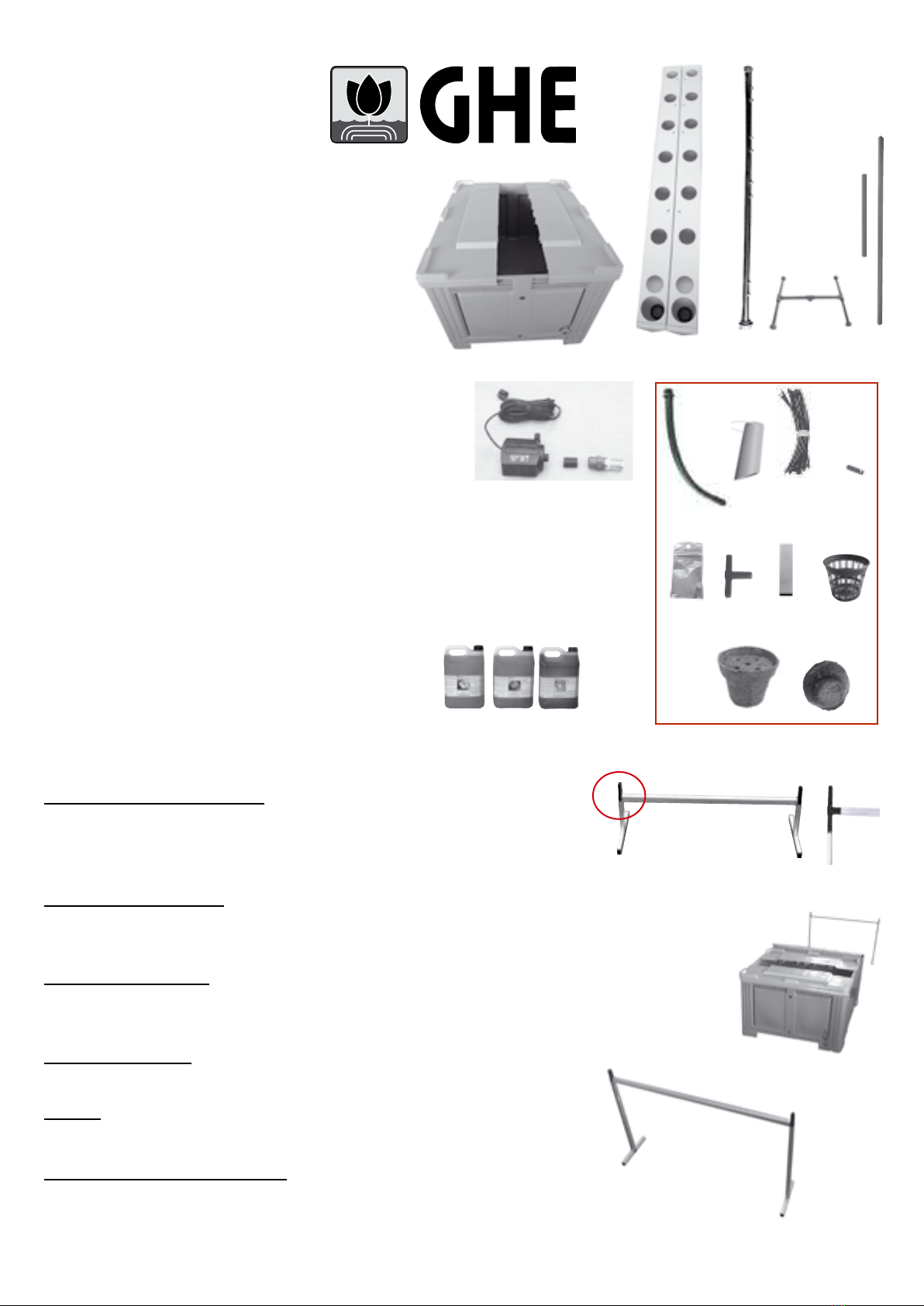
DESCRIPTION
A 1 Reservoir (600 L) and cover in 2 parts
B 8 3 m growing chambers (4 left and 4 right)
C 4 3 m distribution lines
C1 1 connection tubing for manifold
D 6 support structures (2 x 1,20 m + 4 x 80 cm
aluminium bars)
E 1 Pump
3Large plastic bags
Bag N°1 :
F 1 connection tubing
(manifold to pump)
G 8overowtubes(Ø50)
H 56x4,6mmpreassembled
spaghetti tu bing
I 56injectors
J 4 bags with silicone grease
Bag N°2 :
K8 Tee connectors
L 8 x 12 cm alu tubing with black caps
Bag N°3 :
M 120netpotsØ7,5cm
N 5CocoTekpotsØ7,5cm
5CocoTeklinersØ7,5cm
5CocoTekdisksØ7,5cm
O 1 Flora-series5L
1 Set of detailed instructions
ASSEMBLY
The AeroFlos are easy and fast to assemble.
Step 1 – The support system : (designed to carry up to 300 kg/m2, it ensures top stability).
Assemble the aluminium tubing with the parts and connectors (D + L + K) . Use
a small mallet if needed. (g. 1)
Notice the tees (K) at the upper corners. They allow you to add a vertical
structure to hang lights and yo-yos, or to build a protection frame.
Step 2 – The reservoir :
Place the reservoir (A) and the stands at a sufcient distance so that you can
place the growing chambers properly. (g 2). Place the covers on each side of
the reservoir, leaving it open in the middle.
Step 3 – The manifold:
Assemble the distribution lines (C) and the connecting tubing (C1) and place it
on the reservoir and the stands (g. 3 & 3 bis). Introduce the spaghettis (H) into
the distribution lines in a staggered way (g. 4 & 5)
Step 4 – The pump :
Place the pump (E) in the bottom of the reservoir. Connect the manifold to the
pump with the connection tubing (F). (g. 6 & 6 bis).
Notice : leave electric plugs far from the water at all times! To prevent your
pump from burning, never let it run while sucking air or when your system is
empty.
Step 5 – The growing chambers :
• Introduce the overow tubes (G) in the access holes in the chambers. To
make things easier, spread silicone gel (J) around the overows, then gently
Fig. 1
Fig. 2
A
D1
E
IG
K
M
DA C
O
C1B
C
H
F
J
FH
L
N
I
J K M
GE F


