GHH RAND CF Series User manual

Installation Manual Series CF (excluding encapsulated screw compressors) 23042013 Rev. A / May 2007 1 of 60
Installation Manual
Screw Compressor with Oil Injection
Series CF
(excluding encapsulated
screw compressors)

Installation Manual Series CF (excluding encapsulated screw compressors) 23042013 Rev. A / May 2007 2 of 60
Introduction
The purpose of this installation manual is to pro-
vide assistance when fitting the Series CF com-
pressor elements into compressor systems or
groups. All information and specifically data relat-
ing to safety contained in this manual should be
incorperated into the operating company’s opera-
tion manual.
Content of this installation manual is property of
GHH RAND. Reprint and reproduction are pro-
hibited without previous written consent from
GHH RAND.
The details of this installation manual do not enti-
tle to any claims concerning the specified GHH
RAND products. All warranties, other agreements
as well as terms and conditions are in confor-
mance with the general sales and delivery condi-
tions of GHH RAND copies available on request.
Service and maintenance is only permitted to
be carried out by a GHH RAND authorized
service bureau.
GHH RAND reserves the right to modify and im-
prove their products without advance notice.
GHH RAND is not obligated to do these modifica-
tions or improvements on already sold and deliv-
ered products subsequently.
This series is only constructed for operation un-
der following conditions and use:
„Air compression, not containing common or
perceptible added gases, vapours or impu-
rity“!
RNUNG
Operation of this compressor under conditions as
listed under chart 1
−is not permitted by GHH RAND,
−can impact on safety of the operator or other
persons and
−can interfere with warranty claims.
CHART 1
ISATZ
1)
directly aerated respiration for persons
2)
indirectly aerated respiration for persons
3)
operation of compressor in areas beyond
specified temperature range (see Annex 1
Technical data)
4)
operation of compressor in areas of con-
sisting or predictable risks caused by
flammable gases or vapours
THIS COMPRESSOR IS NOT BUILT FOR OP-
ERATION IN POTENTIALLY EXPLOSIVE AR-
EAS AND IS NOT ON ANY ACCOUNT PER-
MITTED TO BE USED IN THESE AREAS.
In case of utilization of spare parts not specified
in the GHH RAND spare parts list, GHH RAND
will not accept responsibilities for consequential
damages.
WARNING!
Utilisation of incorrect coolants can dam-
age rotary screw compressor stages.
We recommend the use of coolant
„PrimeCool“ or „PrimeCool Plus“.
Please contact GHH RAND for further in-
formation!
RECEPTION
The compressor has to be carefully inspected after
recept. Indications of careless handling on the part of
the freight carrier has to be noted upon receipt, par-
ticularly if the compressor will not be unpacked imme-
diately. A declaration of consent signed by the freight
carrier regarding damages detected will simplify the
processing of any subsequent insurance claims.
IMPORTANT INFORMATION
THE GOODS HAVE TO BE IMMEDIATELY
INSPECTED AFTER RECEPTION.
GHH RAND ARE ABSOLVED FROM RESPONSI-
BILITY FOR DAMAGE CAUSED IN SHIPMENT TO
THE GOODS AFTER SIGNATURE OF WAYBILL BY
FREIGHT CARRIER.
.

Installation Manual Series CF (excluding encapsulated screw compressors) 23042013 Rev. A / May 2007 3 of 60
Table of contents
1
General ........................................4
1.1
Intended purpose ..........................................4
1.2
Type designation...........................................4
1.3
Marking .........................................................4
1.4
Information required for inquiries and orders 4
1.5
Sale and service point...................................4
2
Safety...........................................5
2.1
General .........................................................5
2.2
Marking of instructions in the installation
manual ..........................................................5
2.3
Qualification and training of personnel .........5
2.4
Safety conscious operation...........................5
2.5
Safety instructions for the operating
company/operator .........................................6
2.6
Safety instructions for maintenance,
inspection and mounting work ......................6
2.7
Unauthorized conversion and manufacturing
of spare parts ................................................6
2.8
Unauthorized operation modes.....................6
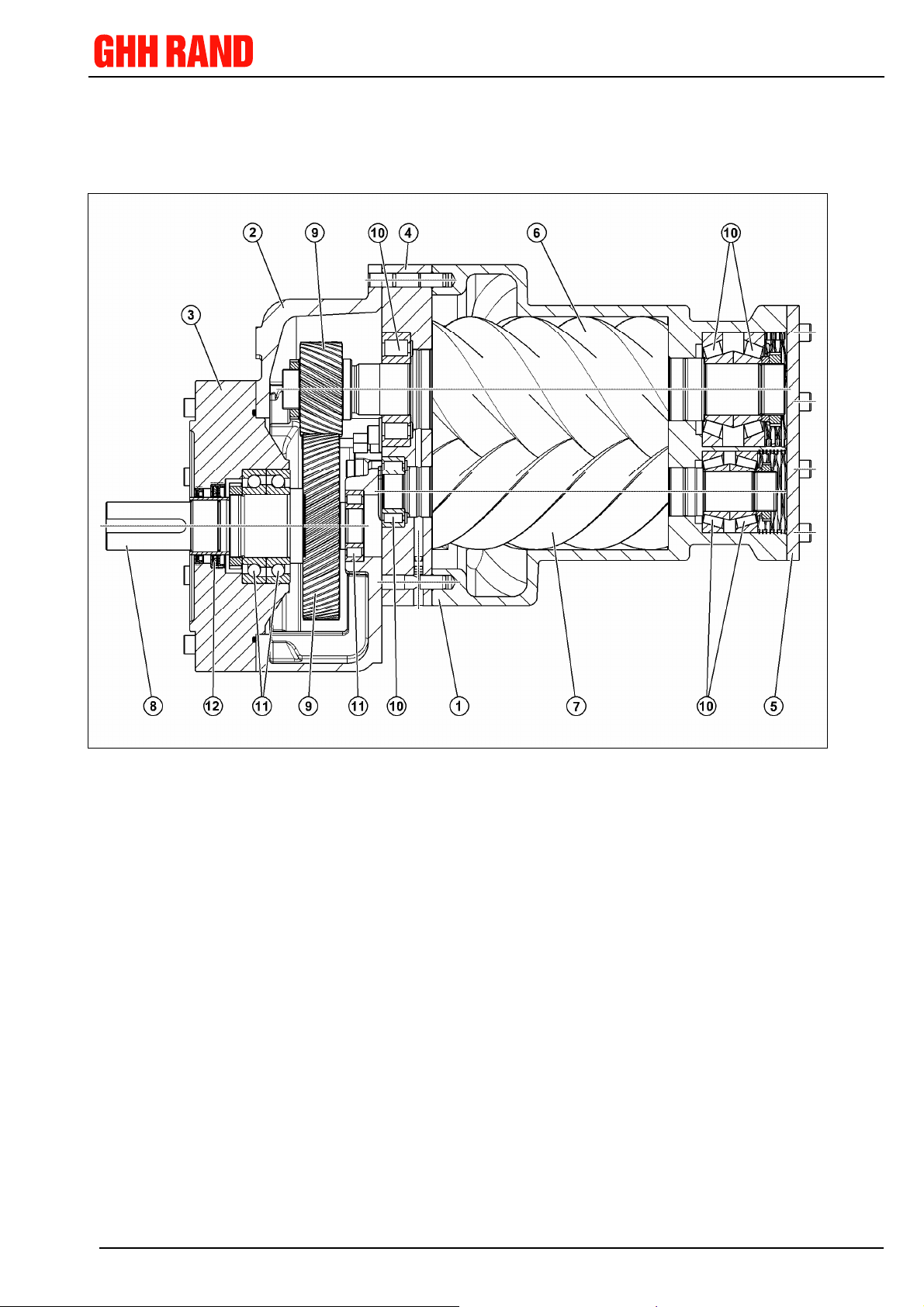
3
Description of product and
accessories .................................7
3.1
Main assemblies of the compressor .............7
3.2
Direct drive....................................................8
3.3
Belt drive .......................................................8
3.4
Gear execution..............................................8
4
Recommendation for plant
construction ................................9
4.1
Electromotor drive piping diagram ................9
4.2
Explanations to the electromotor drive tubing
plan .............................................................11
4.2.1
Start-up .................................................... 11
4.2.2
Operation under load............................... 11
4.2.3
No-load operation.................................... 11
4.2.4
Switch-off ................................................. 12
4.2.5
Oil system................................................. 12
4.3
Explanations to the diesel engine drive
tubing plan ..................................................13
4.3.1
Start-up .................................................... 13
4.3.2
Operation under load............................... 13
4.3.3
No-load operation.................................... 13
4.3.4
Switch-off ................................................. 14
4.3.5
Oil system................................................. 14
4.4
Recommendations for plant protection .......15
4.5
Dew point diagram ......................................17
4.6
Recommendations for Lubricants ..............18
4.6.1
Type of lubricants .................................... 18
4.6.2
Lubricant selection .................................. 18
4.6.3
Admixtures, impurities ............................. 19
4.7
Permissible flow rates .................................19
4.8
Filter fineness..............................................20
4.8.1
Oil filter fineness...................................... 20
4.8.2
Suction air filter fineness .........................20
4.8.3
Explanations to the filter fineness
according to ISO 4572:............................20
4.9
Fitting instructions ...................................... 21
4.9.1
Coupling...................................................21
4.9.2
Belt drive..................................................22
5
Preparation prior to start
operation....................................23
5.1
Filling up oil ................................................ 23
5.2
Checking the direction of rotation.............. 23
6
Maintenance ..............................23
7
Spare parts ................................24
8
Annex I Technical data .............26

Installation Manual Series CF (excluding encapsulated screw compressors) 23042013 Rev. A / May 2007 4 of 60
1 General
1.1 Intended purpose
GHH RAND manufacture and supply the Series
CF compressor stages as built-in elements for
compressed air generation systems or packages.
The compressors are exclusively intended to
compress air within the scope of the specified
technical applications limits.
Any other utilization of compressor beyond these
applications is not usual. The manufacturer is not
liable for resulting defects! The operator is re-
sponsible for the risk only!
For differing utilisation the approval of the
manufacturer is required.
1.2 Type designation
Designation is structured as follows:
CF75GX
Design (digit or letter)
Type
G Integrated gear
L Extended rotor profile
D Direct drive
R Belt drive
Rotor center line distance in mm
Series
1.3 Marking
The type designation is to found on the compres-
sor’s nameplate.
The whole marking has docu-
mentary value and shall not be
removed, modified or made il-
legible.
1.4 Information required for inquir-
ies and orders
When inquiring about and ordering spare parts
and accessories, please state the exact type des-
ignation and the machine number of the com-
pressor.
Required wear- and tear part kits for mainte-
nance in chapter 7.
Original spare parts and
accessories approved by the
manufacturer contribute to
safety.
The use of non GHH RAND
spare parts and or non-approved
accessories will result in the loss
of any liability for the
consequences arising there-
from.
1.5 Sale and service point
Addresses of the sale and service points are to
be found at the end of this installation manual
(section 7).
NOTE
NOTE

Installation Manual Series CF (excluding encapsulated screw compressors) 23042013 Rev. A / May 2007 5 of 60
2 Safety
2.1 General
This installation manual contains basic instruc-
tions to be observed during installation, operation
and maintenance and where necessary shall be
taken over into operating company’s operation
manual of the machine/system into which the
compressor elements are fitted.
Prior to utilization and putting into operation the
compressor personnel shall read these instruc-
tions and those in the operating manual of the
machine/system into which the compressor stage
is fitted. The operating manual must always be
accessible to the personnel.
Not only should the general safety instructions
under this main section „Safety“ be followed, but
also those particular safety instructions added to
the other main sections.
Non-observance of safety instructions will
lead to loss of any claims for indemnity!
2.2 Marking of instructions in the
installation manual
The safety instructions contained in this installa-
tion manual and likely to cause personal hazard if
not observed, have been highlighted by the gen-
eral danger sign
In case of safety instructions likely to endanger
the machine and its function if not observed, the
word
has been inserted.
Notices are highlighted as follows:
2.3 Qualification and training of
personnel
Work on the compressor like operation and main-
tenance shall only be carried out by authorized,
instructed and qualified personnel who are famil-
iar with the safety regulations in force.
The operating company shall precisely define the
scope of responsibilities, the competence and the
supervision of the personnel. If the personnel do
not have the necessary knowledge, they shall be
trained and instructed accordingly.
Repairs or conversions shall only be carried out
by authorized personnel which are always avail-
able from GHH RAND.
2.4 Safety conscious operation
The essential technical safety provisions applica-
ble to the installation, operation and maintenance
of air compressors are contained in the following
publications:
Provisions issued by the craft association
(BGV), in particular:
•BGV A1: General provisions
•BGV A2: Electric systems and working
stock
•BGR 500: Operation of work equipment,
Part 1, Chapter. 2.11-Part 2:
Compressor and vacuum
pumps
Standards, in particular:
•ISO 12100: Safety of machines
•EN 1012-1: Compressors and
vacuum pumps,
safety requirements;
Part 1: Compressors
•ISO 5388 Stationary air compressors
- safety rules and code of
practice
Regulations, in particular:
•Pressure Equipment Directive
•Regulation on pressure vessels, pressure
gas vessels and filling systems
The last revision of these provisions shall always
be applicable.
NOTE
WARNING

Installation Manual Series CF (excluding encapsulated screw compressors) 23042013 Rev. A / May 2007 6 of 60
Local condition rules & regulations and especially
safety regulations must be adhered to in full. In
the event of concurrent regulations, please al-
ways comply with the most stringent.
2.5 Safety instructions for the oper-
ating company/operator
The operating company is responsible that the
compressor is always in safe operating condition.
Damaged or non-operating compressors shall be
replaced without delay.
2.6 Safety instructions for mainte-
nance, inspection and mounting
work
Service and maintenance is only permitted to be
carried out by a GHH RAND authorized service
bureau
The machine/system should only be worked on
whilst shut down and isolated. Following the ma-
chine/system shutdown procedure described in
the operating manual is imperative.
Disposure of oils and greases in accordance with
local legislation is mandatory.
After completion of work, immediately reinstall
and reset into operation all safety and protection
devices.
Before resuming operation, the points mentioned
in section “Putting into operation“ (section 5) shall
be observed.
2.7 Unauthorised conversion and
manufacturing of spare parts
Conversions or modifications of the compressor
are not permitted unless agreed in writing by
GHH RAND.
Original spare parts and accessories approved
by the manufacturer contribute to safety.
The use of other spare parts and non-approved
accessories may result in the loss of liability!
2.8 Unauthorized operation modes
Without written consent of GHH RAND, the com-
pressor shall not be operated under other condi-
tions than those described in annex “Technical
data”.

Installation Manual Series CF (excluding encapsulated screw compressors) 23042013 Rev. A / May 2007 7 of 60
3 Description of product and accessories
3.1 Main assemblies of the compressor
Sectional drawing of a screw compressor as an example
Main components: Rotors: Seals:
1 Rotor casing 10 Rotor bearing 12 Shaft seal
2 Gear casing 11 Drive shaft bearing
3 Gear case cover
4 Bearing casing
5 Cover
6 + 7 Rotor pairs (Mail + Fe-
male)
8 + 9 Set of wheels (driving
wheel with shaft + pin-
ion)

Installation Manual Series CF (without incapsulated screw compressors) 23042013 Rev. A / May 2007 8 of 60
3.2 Direct drive
The compressor can be directly driven by a mo-
tor, at the motors operating speed, via a coupling
which is directly mounted on the male motor
shaft.
Installing and fastening with threaded bores on
the underside of the compressor.
A correct alignment of motor/coupling/compres-
sor is absolutely necessary.
3.3 Belt drive
Adapting the motor speed to the required operat-
ing speed of the compressor is possible means
on an intermediate belt drive.
Application of reference as per Annex, section 8
„Technical data“.
Installing and fastening with threaded bores on
the underside of the compressor.
A correct alignment of motor/belt pulleys/com-
pressor is absolutely necessary.
3.4 Gear drive
Driving takes place by means of an integrated
gear that increase or decreases the motor speed
to the required operating speed of the compres-
sor.
The compressor can either be directly flanged by
flange connection to the driving motor using a
coupling casing, or be installed or fastened using
threaded bores on the underside of the compres-
sor.

Installation Manual Series CF (without incapsulated screw compressors) 23042013 Rev. A / May 2007 9 of 60
4 Recommendation for plant construction
The following piping diagram and descriptions are non-committal examples and provide
information on possible forms of execution. They do not dispense from the liability to
consider the actual operating conditions. Existing safety regulations (see also section 2
“Safety”) shall be observed. GHH RAND does not assume any liability or warranty for the
represented circuits, descriptions and other information.
4.1 Electromotor drive piping diagram
NOTE

Installation Manual Series CF (without incapsulated screw compressors) 23042013 Rev. A / May 2007 10 of 60
List of equipment
1 Screw compressor
2 Drive motor with coupling / belt
3 Suction filter
4 Suction valve
5 Adjustable throttle valve
6 Contact manometer for compressor
discharge pressure
7 Quick-action temperature controller for
the discharge temperature *)
8 Non-return valve
9 Oil reservoir and coarse separator
10 Manometer oil reservoir pressure
11 Quick-action temperature controller for
temperature in the oil reservoir *)
12 Pressure controller (relief pressure)
13 Safety Valve (discharge pressure)
14 Fine separator
15 Difference pressure controller for fine
separator
16 Relief valve
17 Minimum pressure valve
18 Non-return valve
19 Pressure controller (mains pressure)
20 Electromagnetic 3/2 way valve
21 Non-return valve
22 Non-return valve
23 Hand switch Load / No-load
24 Manometer for the mains pressure
25 Non-return valve
26 Oil filter
27 Oil filter
28 Oil cooler
29 Thermostatic valve
30 Oil stop valve
31 Adjustable throttle valve
32 Oil temperature thermometer
33 Sight glass
34 Adjustable throttle valve
35 Non-return valve
36 Oil level indicator – Oil reservoir
37 Oil filler – Oil reservoir
38 Oil drain – Oil reservoir
39 Condensate drain – Oil reservoir
*) typical response time max. 10 seconds; in the
switch-off range, a temperature jump of 10°C
must entail switching within 1 second.

Installation Manual Series CF (excluding encapsulated screw compressors) 23042013 Rev. A / May 2007 11 of 60
4.2 Explanations to the electromo-
tor drive tubing plan
The pressures stated are abso-
lute pressures.
4.2.1 Start-up
Suction valve [4] is closed as no control pres-
sure is applied yet.
To allow for intake of a small amount of air for
pressure build-up, the throttle valve [5] is set
as to provide for a pressure of > 0.1 bar
ahead of the compressor.
An incorrect construction/design of suction
valve might lead to problems/damages
with/of compressor.
Throttle valve [5] is required only
if suction valve [4] does not have
an adjusting possibility for di-
rected leakage (e.g. provision of
bores in a throttle).
Hand switch [23] is closed.
Load position: Electric circuit for relief valve
[16] and the 2/3 way valve [20] is closed.
At the start of the motor, relief valve [16]
closes (idle: open), the 3/2 way valve [20]
opens.
Minimum pressure valve [17] is closed, thus
separating the compressor system from the
mains. Minimum pressure valve must be ad-
justed to a minimum pressure of 4.5 bar.
To protect motor [2] and coupling, starting the
motor should only be possible if there is a
pressure maximum of 2 bar behind the com-
pressor.
4.2.2 Operation under load
When required control pressure has been
reached, the suction valve [4] opens.
Minimum pressure valve [17] opens only after
a pressure of approx. 4.5 bar has built-up in
the compressor system. This pressure en-
sures a sufficient oil supply to the compressor
during operating under load.
The compressor boosts into the mains as
soon as the system pressure ahead of non-
return valve [18] exceeds the pressure of the
mains.
4.2.3 No-load operation
No-load operation is possible:
1. Automatically in case of mains pressure is
higher than the upper switch-point of pres-
sure controller [19].
2. Upon actuation of hand switch [23].
(No-load position: Power supply for relief val-
ve [16] and 3/2 way valve [20] is interrupted).
The sequence is identical:
3/2 way valve [20] closes because of the ab-
sence of current, and suction valve [4] closes
because of the absence of control pressure.
At the same time, the absence of current
opens relief valve [16], the pressure in the
compressor system drops.
Non-return valve [18] separates the com-
pressor system from the mains.
(In addition, minimum pressure valve [17]
closes at a pressure of approx. 4.5 bar.)
As the mains pressure drops and reaches the
lower switch-point, pressure controller [19]
again closes the electric circuit.
This makes relief valve [16] close and 3/2
way valve [20] open. The control pressure
from the mains opens immediately suction
valve [4] by means of non-return valve [22].
Further sequence as described under “Op-
eration under load”.
NOTE
NOTE

Installation Manual Series CF (excluding encapsulated screw compressors) 23042013 Rev. A / May 2007 12 of 60
4.2.4 Switch-off
Switch-off takes place intentionally upon ac-
tuation of the motor circuit breaker or by
means of safety cut out in the event of:
•A pressure behind the compressor of more
than p
2
+ 0.3 bar by contact manometer [6],
•A temperature behind the compressor of
more than 110 °C by quick-action tempera-
ture controller [7],
•a temperature in oil reservoir [9] of more
than 110 °C by quick-action temperature
controller [11].
Switch-off must be initiated at a
temperature of not more than
120°C.
For safety reasons the motor should be swit-
ched-off from No-load position.
If the motor comes to standstill before the
system is completely relieved, non-return val-
ve [8] prevents reverse motion caused by
backward pressure drop.
Oil stop valve [30] is generally open. If at
switching-off, the motor comes to standstill
before the system has been relieved, a pres-
sure difference occurs between the pressure
side of the compressor and the oil line of oil
stop valve [30] and closes oil stop valve [30].
This ensures that the compressor cannot be
filled with oil from the oil system due to the
pressure drop (risk of a liquid hammer when
starting-up again).
4.2.5 Oil system
Utilizing the pressure difference, the oil collected
in the oil reservoir/coarse separator is used to
supply the compressor with oil.
By means of adjustable throttle valve [31], the
oil injection amount into the compression
chamber (connection A) is adjusted in a way
to provide for the desired discharge tempera-
ture (between the dew point temperature and
110 °C).
By means of the thermostatic valve [29], the
oil intake temperature for the compressor
stage is kept approximately constant depend-
ing on operating condition and dew point.
Connection F is used to return the oil col-
lected in fine separator [14] into compression
chamber of the compressor. With minimum
discharge pressure, adjust throttle valve [34]
in a way that (visible on sight glass [33]) only
a small amount of air is returned with the oil.
Non-return-valve [35] prevents, that during
relief, oil from the compression chamber is
blown into the open through the fine separa-
tor and relief valve [16].
Non-return valve [25] prevents that oil flows
back from compressor and oil system into the
oil reservoir if, when switching from No-load
to Load, a pressure has already built-up in
the compressor whilst oil reservoir [9] is still
relieved.

Installation Manual Series CF (excluding encapsulated screw compressors) 23042013 Rev. A / May 2007 13 of 60
4.3 Explanations to the diesel en-
gine drive tubing plan
The pressures stated are abso-
lute pressures.
4.3.1 Start-up
Suction valve [4] is on idle position (minimum
discharge) as no control pressure is applied
yet.
To allow for intake of a small amount of air for
pressure built-up, the throttle valve [5] is set
as to provide for a pressure of > 0.1 bar
ahead of the compressor. An incorrect con-
struction/design of suction valve might cause
problems/damages with/of compressor.
Throttle valve [5] is required only
if suction valve [4] does not have
an adjusting possibility for di-
rected leakage (e.g. provision of
bores in a throttle).
Hand switch [23] is closed.
Load position: Electric circuit for relief valve
[16] and the 3/2 way valve [20] is closed.
At the start of the motor, relief valve [16] (idle:
open), the 3/2 way valve [20]. The diesel en-
gine is running with minimum speed.
Minimum pressure valve [17] is closed, thus
separating the compressor system from the
mains. Minimum pressure valve must be ad-
justed to a minimum pressure of 4.5 bar.
To protect motor and coupling [2], starting the
motor should only be possible if there is a
maximum pressure of 2 bar behind the com-
pressor.
4.3.2 Operation under load
When required control pressure has been
reached, control cylinder [40] regulates the
diesel engine to maximum speed and suction
valve [4] opens at the same time.
Minimum pressure valve [17] opens only after
a pressure of approx. 4.5 bar has built-up in
the compressor system. This pressure en-
sures a sufficient oil supply of the compressor
during operation under load.
The compressor boosts into the mains as
soon as the system pressure ahead of non-
return valve [18] exceeds the pressure of the
mains.
4.3.3 No-load operation
No-load operation is possible:
1. Automatically in case of mains pressure is
higher than the upper switch-point of pres-
sure controller [19].
2. Upon actuation of hand switch [23]. (No-load
position: Power supply for relief valve [16]
and 3/2 way valve [20] is interrupted).
The sequence is identical:
3/2 way valve [20] closes because of the ab-
sence of current. The absence of control
pressure regulates the diesel engine to mini-
mum speed and opens suction valve [4] at
the same time.
At the same time, the absence of current o-
pens relief valve [16], the pressure in the
compressor system drops.
Non-return valve [18] separates the com-
pressor system from the mains.
(In addition, minimum pressure valve [17]
closes at a pressure of approx. 4.5 bar).
As the mains pressure drops and reaches the
lower switch-point, pressure controller [19]
again closes the electric circuit.
This makes relief valve [16] close and 3/2 ]
way valve [20] open.
The control pressure from the mains immedi-
ately regulates the diesel engine to maximum
speed and opens suction valve [4] at the
same time by means of non-return valve [22]
and control cylinder [40]. Further sequence
as described under “Operation under load“.
NOTE
NOTE

Installation Manual Series CF (excluding encapsulated screw compressors) 23042013 Rev. A / May 2007 14 of 60
4.3.4 Switch-off
Switch-off takes place intentionally upon ac-
tuation of the motor circuit breaker or by
means of safety cut out in the event of:
•A pressure behind a compressor of more
than p
2
+ 0.3 bar by contact manometer [6],
•A temperature behind the compressor of
more than 110 °C by quick-action tempera-
ture controller [7],
•A temperature in oil reservoir [9] of more
than 110 °C by quick-action temperature
controller [11].
Switch-off must be initiated at a
temperature of not more than
120°C.
For safety reasons the motor should be swit-
ched-off from No-load position.
The 3/2 way valve [20] closes and relief valve
[16] opens, because of the absence of cur-
rent.
The absence of control pressure regulates
the diesel engine to minimum speed and
closes suction valve [4] at the same time.
Subsequently the diesel engine can be
switched-off.
If the motor comes to standstill before the
system is completely relieved, non-return val-
ve [8] prevents reverse motion caused by
backward pressure drop.
Oil stop valve [30] is generally open. If at
switching-off, the motor comes to standstill
before the system has been relieved, a pres-
sure difference occurs between the pressure
side of the compressor and the oil line of oil
stop valve [30] and closes oil stop valve [30].
This ensures that the compressor cannot be
filled with oil from the oil system due to the
pressure drop (risk of a liquid hammer when
starting-up again).
4.3.5 Oil system
Utilizing the pressure difference, the oil collected
in the oil reservoir/coarse separator is used to
supply the compressor with oil.
By means of adjustable throttle valve [31], the
oil injection amount into the compression
chamber (connection A) is adjusted in a way
to provide for the desired discharge tempera-
ture (between dew point temperature and
110°C).
By means of the thermostatic valve [29], the
oil intake temperature fort he compressor
stage is kept approximately constant depend-
ing on operating condition and dew point.
Connection F is used to return the oil col-
lected in fine separator [14] into compression
chamber of the compressor. With minimum
discharge pressure, adjust throttle valve [34]
in a way that (visible on sight glass [33]) only
a small amount of air is returned with the oil.
Non-return valve [35] prevents, that during
relief, oil from the compressor chamber is
blown into the open through the fine separa-
tor and relief valve [16].
Non-return valve [25] prevents that oil flows
back from compressor and oil system into the
oil reservoir if, when switching from No-load
to Load, a pressure has already built-up in
the compressor whilst oil reservoir [9] is still
relieved.

Installation Manual Series CF (excluding encapsulated screw compressors) 23042013 Rev. A / May 2007 15 of 60
4.4 Recommendations for plant
protection
Maximum permissible discharge temperature:
110 °C. Temperature monitoring is prescri-
bed.
Minimum permissible discharge pressure:
6 bar (with opened suction valve)
Maximum permissible discharge pressure,
see technical data sheets.
The minimum discharge temperature should
be above the dew point temperature. If this is
not the case, the water vapour contained in
the air condenses. The water accumulating in
the oil affects the lubricant and may lead to
bearing damages.
Existing adjustment possibility for the oil in-
jection amount to influence on the discharge
temperature.
The system must be designed so that, when
the motor is at standstill, any still existing
pressure cannot relieve backward through
the compressor unit (reverse motion of com-
pressor) or through oil system (compressor
fills with oil; risk of liquid hammer when start-
ing-up again).
Generally, the unit does not require an oil
pump. It is sufficiently supplied with oil due to
the pressure differences between the oil res-
ervoir that is under discharge pressure, and
the individual connection points. For particu-
lar operating conditions (e.g. extremely low
temperatures or pressures <6 bar), sufficient
oil supply must be ensured by means of an
external oil pump.
The size of the oil reservoir/coarse separator
is decisive for the degree of preliminary sepa-
ration of the oil from the compressed air. A
large reservoir means a low flow speed and
thus a good oil separation. The build up the
required lubrication oil pressure as rapidly as
possible at start-up, a minimum pressure
valve should be fitted behind the separator
ahead of the mains.
At every stage of run-up, the starting torque
of the motor must be higher than the starting
torque of the compressor. The run-up time of
the motor should not be less than 2 seconds.
Drive motor has to be designed that no axial
force can affect jackshaft of compressor. To
compensate magnetic forces and forces caused
by heat expansion the motor bearing on the cou-
pling side has to be designed as fix bearing. Axial
forces can damage gears in a gear box driven
airend!
Short interruption of operation caused by voltage
break-downs of the electric power create dy-
namic processes within the drive train with high
loads exceeding several times the nominal loads
which causes overheating of the drive train and
its damage. Warranty claims caused by this kind
of damages will definitively be rejected!
Motor, coupling, gear box/belts and airend com-
bination, could create a situation resulting in a
package susceptible to damaging vibration fre-
quencies. To ensure safe and free of vibration
operation of the system, torsional vibration
analysis must be undertaken. The motor and
airend frequencies have to be considered in this
calculation.
Airend Installation
When loading or transporting airends ensure that
the specified lifting and tie down points are used.
It is recommended that the machine be moved
using the fork lift slots in the airend. The airend
has to be installed without any restraints. Be-
cause of acoustic reasons vibration-free installa-
tion has to be considered (avoidance of struc-
ture-borne noise)
Synthetic components in compressed air units
might be corroded by synthetic lubricants or addi-
tives contained in mineral lubricants. Compatibil-
ity has to be checked regarding utilisation of lu-
bricant. We recommend coolant „PrimeCool“ or
„PrimeCool Plus“.
Compressed Air Piping
The compressed air piping should have at least
the same diameter as the discharge port of the
compressor. All pipes and fittings have to be de-
signed and built according to the max. discharge
WARNING
WARNING

Installation Manual Series CF (excluding encapsulated screw compressors) 23042013 Rev. A / May 2007 16 of 60
pressure under consideration of Safety Regula-
tions mention according to chapter 2.4
Do not load any additional forces on the flanges
of the airend. Heat expansion and vibrations are
to compensated by usage of appropriate devices.
Screw compressors and piston compressors
should not be installed at the same air network
without the installation of an appropriate pressure
compensating gas pulsation vessel.
WARNING

Installation Manual Series CF (without incapsulated screw compressors) 23042013 Rev. A / May 2007 17 of 60
4.5 Dew point diagram

Installation Manual Series CF (without incapsulated screw compressors) 23042013 Rev. A / May 2007 18 of 60
4.6 Recommendations for
Lubricants
4.6.1 Type of lubricants
In consideration of the high stresses to which
lubricants are subjected in screw compressors
with oil injected cooler, it is recommended to ex-
clusively use non-aging and anti-corrosive oil
grades with a low foaming tendency that have
been demonstrated to be suitable for application.
GHH RAND recommend stable and proven char-
acteristic lubricants:
„PrimeCool“ on mineral basis &
„PrimeCool Plus“ on synthetic basis.
In case of utilisation of another lubricant, it is
mandatory that oil specification as follows must
be observed.
Technical specification of PrimeCool (mineral
lubricant)
Properties Unit Test method
Density at 15 °C kg/m3 874 DIN 51 757
Kinematic viscosity
at 40 °C
at 100 °C
mm2/s
46
6,8
DIN 51 550 &
DIN 51 562-1
Viscosity index 101 DIN ISO 2909
Flashpoint °C 230 DIN ISO 2592
Pourpoint °C -31 DIN ISO 3016
Neutralization number TAN mgKOH/g 0,2 DIN 51 558-2
Demulsification at 54 °C min 15 DIN 51 599
Foaming
Seq.I: 24 °C
Seq.II: 93,5 °C
Seq.III after 93,5 °C
ml/ml
ml/ml
ml/ml
0/0
20/
0
5/0
ASTM D 892
ASTM D 892
ASTM D 892
Air release at 50°C min 3 DIN 51 381
Technical specification of PrimeCool Plus (syn-
thetic lubricant)
Properties Unit Test method
Density at 15 °C kg/m3 837 DIN 51 757
Kinematic viscosity
Bei 40 °C
Bei 100 °C
mm2/s
46
7,8
DIN 51 550 &
DIN 51 562-1
Viscosity index 139 DIN ISO 2909
Flashpoint °C 278 DIN ISO 2592
Pourpoint °C <-60 DIN ISO 3016
Neutralization number TAN mgKOH/g 0,4 DIN 51 558-2
Demulsification at 54 °C min 15 DIN 51 599
Foaming
Seq.I: 24 °C
Seq.II: 93,5 °C
Seq.III: after 93,5 °C
ml/ml
ml/ml
ml/ml
5/0
20/0
5/0
ASTM D 892
ASTM D 892
ASTM D 892
Air release at 50°C min 3 DIN 51 381
Different specifications will lead to non-warranty!
As deterioration of lubricant strongly depends on
conditions of the airborne area and the operating
method of the compressor, regular checks of the
oil quality have to be carried out and docu-
mented. In either case the interval of oil change
has to be observed according to maintenance
instructions.
In case of utilisation of synthetic lubricants, com-
patibility with compressor component material
has to be ensured. Furthermore oil additives
within the oil must not chemically react to the
condensate which is unavoidably developed at
start-up of compressor unit.
Authorisation for other lubricants other than
PrimeCool / PrimeCool Plus will not be given!
4.6.2 Lubricant selection
Viscosity is the most important criterion of any
lubricant. To avoid damage to the bearings, a
minimum viscosity of 15 mm²/s (cSt) is required
for the selected oil injection temperature. As vis-
cosity changes with temperatures, the recom-
mendations as per the following table are appli-
cable depending on respective injection tempera-
tures:
Injection temperature °C up to 50 up to 60 up to 70
ISO-Viscosity class VG 32 VG 46 VG 68
Viscosity at 40 °C mm²/s 28.8-35.2 41.4-50.6 61.2-74.8
Flashpoint COC °C >200 >210 >220
The pour point is min. 5 °C below the lowest am-
bient temperature.
On machinery which is continuously operated at
very low speeds (male-rotor tip speed less than
15 m/s), the respective next higher viscosity
class is to be used in accordance with the above
table.
To avoid wearing effects on antifriction bearings
and driving gears to the greatest possible extent,
only those oil grades are accepted which contain
wear-reduction additives to provide FZG load
stage no. 10 as a minimum.
WARNING

Installation Manual Series CF (excluding encapsulated screw compressors) 23042013 Rev. A / May 2007 19 of 60
4.6.3 Admixtures, impurities
Water
Water within the lubricant can lead to pene-
tration of lubricating film. Therefore final tem-
perature should always be beyond the dew
point in so far as no water can precipitate in
oil circuit.
Dirt
Abrasive impurities, such as grinding or blast-
cleaning residues, as a rule will create profile
damages and major bearing damage. There-
fore, best-possible filtration of the lubricant is
necessary (recommended filter fineness β
25
=
75 according to DIN ISO 4572).
When using oil filters with an internal bypass
as specified for instance in the implementing
regulations of German accident prevention
codes for avoidance of excessive tempera-
tures, it must further be ensured that this is
never activated. Particular attention has to be
paid to the fact that the bypass is not even
opened in the event of a machine cold start if
the pressure loss rises through the higher
viscosity. Such an effect is particularly dan-
gerous as in such a case any previously fil-
tered-out residues would be washed into the
compressor range as well as into the bear-
ings at a great concentration together with
the oil.
Foreign material in suction air
When installed in a marine atmosphere, a
high air humidity accompanied by chlorine
(salt) or a chemical atmosphere with gas ad-
mixtures in the intake air may greatly affect
the normal properties of lubricants.
It is not possible in these cases to make any
general recommendation.
4.7 Permissible flow rates
The following values are recommended as
maximum flow rates in pipes:
Air pipe
Suction side 15.0 – 20.0 m/s
Pressure side (air only) 20.0 – 25.0 m/s
(air/oil mixture) 6.0 – 8.0 m/s
Oil pipe *)
Pressure line 1.0 – 2.5 m/s
“Free” Oil drain 0.1 – 0.2 m/s
*) The stated flow rates are valid for the usual
viscosities of 32 – 68 cSt in the normal tempera-
ture range between 40°C and 80°C

Installation Manual Series CF (excluding encapsulated screw compressors) 23042013 Rev. A / May 2007 20 of 60
4.8 Filter fineness
4.8.1 Oil filter fineness
Mesh width max. 0.010 mm (10 µm)
For normal operating conditions, filters with a
fineness according to DIN ISO 4572:
β
25
= 75
are recommended.
It is recommended to filter the oil while filling the
oil reservoir, even when filling with fresh clean oil
to prevent any contamination entering the system
In this connection, a fineness according to DIN
ISO 4572:
β
6
= 100
is recommended (see chapter
4.6.3).
The same applies for preservation oils and rins-
ing oils to clean the lubrication system.
4.8.2 Suction air filter fineness
Mesh width max. 0,020 mm for normal indus-
trial air
4.8.3 Explanations to the filter
fineness according to ISO 4572:
•1. Example: β
25
= 75
98.7 % of the 25 µm particles are filtered
out of the oil.
•2. Example: β
6
= 100
99 % of 6 µm particles are filtered out of
the oil.
Particle size in µm
Calculation value for the permeabil-
ity rate as follows:
1 / 75 = 1.3 %
The retention degree is:
100 % - 1,.3 % = 98.7 %
1 / 100 = 1 %
The retention degree is:
100 % - 1 % = 99 %
This manual suits for next models
15
Table of contents