GHIELMETTI GKV 2x11x14 621 SS K User manual

Tripping matrix for Generator Protection Systems
GKV 2x11x14 621 SSK (7UW50) –250 VDC
Part. No. 674.114.913.02
Manual
Edition 04/2020

GHIELMETTI AG –7UW50 - Technische Dokumentation ROR/09.02.2021 Page 2 of 19
Contents
1Conformity.................................................................................................................................................................................3
2Introduction3
3Warranty.....................................................................................................................................................................................3
4Safety Considerations ...........................................................................................................................................................3
4.1 General...............................................................................................................................................................................3
4.2 Safety Earth Ground......................................................................................................................................................4
5Installation .................................................................................................................................................................................4
5.1 Initial Inspection .............................................................................................................................................................4
5.2 Before Applying Power................................................................................................................................................4
5.3 Servicing ............................................................................................................................................................................4
6Disclaimer ..................................................................................................................................................................................4
7Functional description ..........................................................................................................................................................4
8Mode of Operation ................................................................................................................................................................5
9Block Diagram..........................................................................................................................................................................6
10 Control elements of the Tripping Matrix.......................................................................................................................7
10.1Connecting and Diode plugs.....................................................................................................................................7
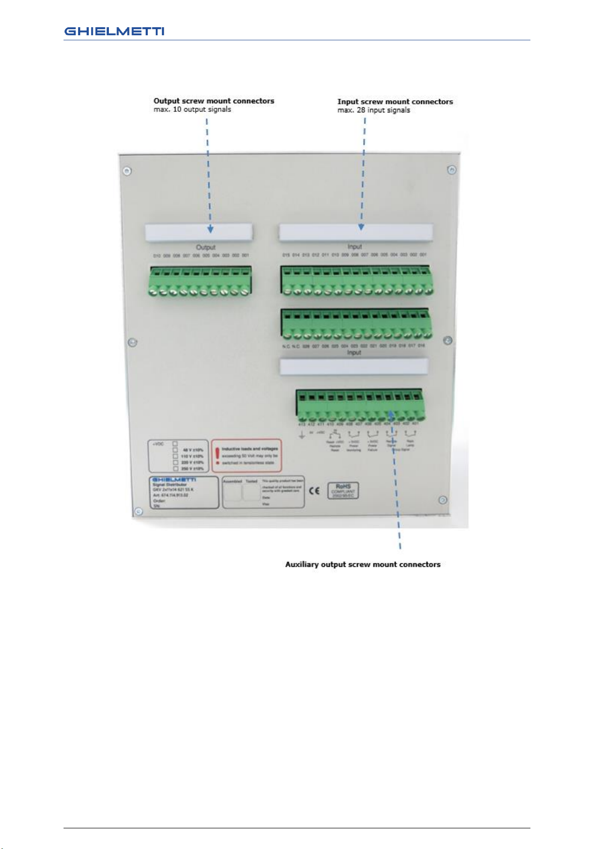
11 Interconnecting the Tripping Matrix...............................................................................................................................8
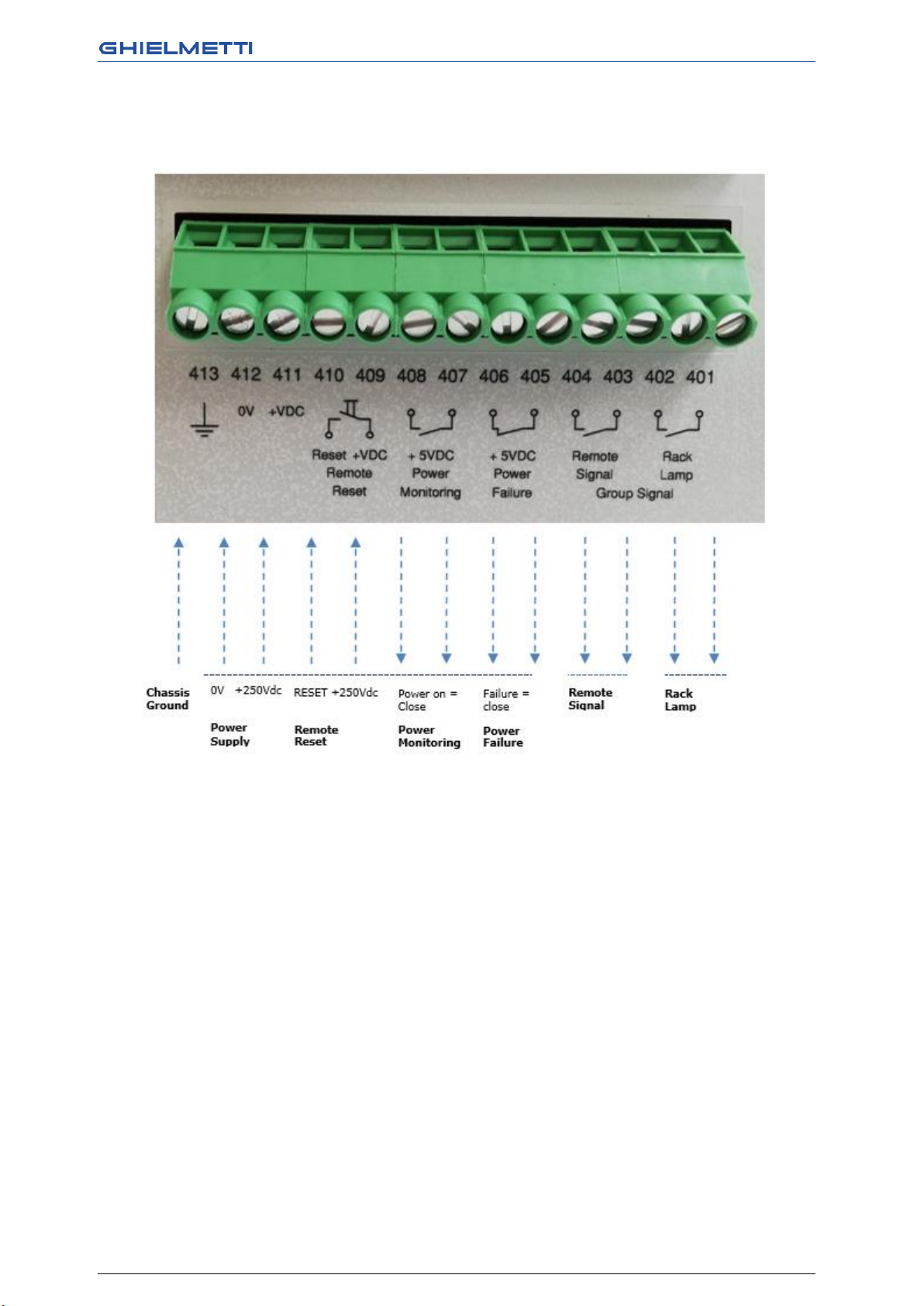
11.1Auxiliary output screw mount connectors...........................................................................................................9
12 Installation instruction ....................................................................................................................................................... 10
12.1Unpacking and repacking........................................................................................................................................ 10
12.2Preparations .................................................................................................................................................................. 10
12.2.1Mounting and connections............................................................................................................................................ 10
12.2.2Checking the rated data.................................................................................................................................................. 10
12.2.3Connections ......................................................................................................................................................................... 10
13 Operating Instructions....................................................................................................................................................... 11
13.1Safety precautions ...................................................................................................................................................... 11
13.2Operation of the device............................................................................................................................................ 11
13.2.1Marshalling of the trip commands .............................................................................................................................. 11
13.3Test and commissioning .......................................................................................................................................... 12
13.3.1General................................................................................................................................................................................... 12
13.3.2Tripping test......................................................................................................................................................................... 12
13.4Making ready for service.......................................................................................................................................... 12
14 Dimensions............................................................................................................................................................................. 14
14.1Front view....................................................................................................................................................................... 14
14.2Back view........................................................................................................................................................................ 15
14.3Side view......................................................................................................................................................................... 16
15 Specifications......................................................................................................................................................................... 17
16 Ordering Data ....................................................................................................................................................................... 18
17 Service condition and repairs.......................................................................................................................................... 18
17.1Replace the mini-fuse................................................................................................................................................ 18

GHIELMETTI AG –7UW50 - Technische Dokumentation ROR/09.02.2021 Page 3 of 19
1Conformity
This product is in conformity with the directive of the Council of the European Communities on the
approximation of the laws of the Member States relating to electromagnetic compatibility (EMC
Council Directive 89/33 6/EEC) and concerning electrical equipment for application within specified
voltage limits (Low-voltage directive 73/ 23 EEC).
Conformity is proved by tests that had been performed according to article 1 0 of the Council
Directive in accordance with the generic standards EN 5008 1 - 2 and EN 5008 2- 2 (for EMC
directive) and the standards EN 60 255-6 (for low-voltage directive) by GHIELMETTI AG.
The device is designed and manufactured for application in industrial environment.
The device is designed in accordance with the international standards of IEC 255 and the German
standards DIN 57 435 part 303 (corresponding to VDE 0435 part 303).
2Introduction
Thank you for choosing a GHIELMETTI product.
We are convinced that your choice will prove to be a wise and worthy decision for many years to
come. Your GHIELMETTI product has been tested for performance at the factory according to the
specifications given for the system in this manual. However, before putting the device into
operation we kindly ask you to read this manual and act according to the instructions given. All
information given in this document is property of GHIELMETTI AG. To the knowledge of
GHIELMETTI AG there are no errors in the manual.
Should any errors be discovered, please notify us. GHIELMETTI will under no circumstances accept
responsibility neither for errors in this manual, nor consequences of such errors.
3Warranty
GHIELMETTI warrants products for two years from date of purchase against defects in materials and
workmanship. During the warranty period, GHIELMETTI will, at its option, either repair or replace
products that prove to be defective. The warranty does not cover any defects caused by accident,
misuse, neglect, improper or inadequate installation or maintenance by buyer, buyer-supplied
software or interfacing, unauthorized modification, operation outside of the environmental
specifications for the product, or improper site preparation or maintenance.
4Safety Considerations
4.1 General
This product and related documentation must be reviewed for familiarization with safety
markings and instructions before operation. This product has been designed and tested in
accordance with international standards.

GHIELMETTI AG –7UW50 - Technische Dokumentation ROR/09.02.2021 Page 4 of 19
4.2 Safety Earth Ground
This is a Safety Class 1 product (a protective earth terminal GND is provided). An uninterrupted
safety earth ground must be provided from the main power source to the product input wiring
terminals, power, cord, or supplied power cord set. Whenever it is likely that the protection has
been impaired, the product must be made inoperative and secured against any unintended
operation.
5Installation
5.1 Initial Inspection
Check the contents of the shipment for completeness and possible transport damage. If the
contents are incomplete or damaged, contact GHIELMETTI immediately to get the concerned parts
repaired or replaced.
5.2 Before Applying Power
Verify that the product is configured to match the available main power source per the input power
configuration instructions provided in this manual.
5.3 Servicing
Servicing, adjustments, maintenance or repair of this product may be performed by qualified
personnel only.
6Disclaimer
This instruction manual does not purport to cover all details in equipment, nor to provide for every
possible contingency to be met in connection with installation, operation or maintenance. Should
further information be desired or should particular problems arise which are not covered sufficiently
for the purchaser's purpose, the matter should be referred to the local GHIELMETTI sales office.
The contents of this instruction manual shall not be-come part nor modify any prior or existing
agree-ment, commitment or relationship. The sales contract contains the entire obligations of
GHIELMETTI. The warranty contained in the contract between the parties is the sole warranty of
GHIELMETTI. Any statements contained herein do not create new warranties nor modify the existing
warranty.
7Functional description
The tripping matrix GKV 7UW50 is a component of a generator protection system. The tripping
matrix provides a transparent, easily programmable facility for combining output commands of the

GHIELMETTI AG –7UW50 - Technische Dokumentation ROR/09.02.2021 Page 5 of 19
trip outputs of individual protection devices with plant items such as the circuit-breakers, de-
excitation etc. The matrix was developed for marshalling tripping commands of large power
stations. With its help, the tripping schematic can be temporarily changed, e.g. in case of a
generator circuit- breaker revision. If the software matrix incorporated in each generator protection
unit is used for marshalling the tripping commands, the marshalling in the protection units must
be changed for this purpose.
The tripping matrix assigns the tripping signals arriving at the matrix columns (from the solid-state
protection relays) to the freely programmable matrix lines to which the tripping modules are
connected
8Mode of Operation
The tripping matrix GKV 7UW50 has 2x14 columns (for 28 signals from protection units) and 10
rows (for 10 signals to tripping modules). High reliability diode plugs (black handle) are used for
programming the matrix, the reliability being attained by generous over-rating with respect to
forward current and reverse voltage.
The diode plugs are inserted from the front and enable any vertical column (signals from the protec-
tion relays) to be connected to any horizontal line so that the tripping signals can be transmitted
to the tripping module. Each column has a LED for indicating tripping commands.
The display is stored. Each additional outgoing tripping command received additionally sets a
group memory, which, for example, can be used for remote signalling and switching a cubicle lamp.
All signals remain stored even when the tripping channels are interrupted or when the red central
connecting plug is removed.
The memories can be reset directly by a push-button "Reset" or by remote reset. Also the function
of all LED’s may be checked by pressing the "Reset" button. The power supply of the relays and
memory functions is 250VDC and feed an additional 5 VDC voltage for the LED function. The
monitoring of the power supply is done by two relay contacts.
Optional: A lockable acryl-glass-cover inhibits unauthorised access to the programming matrix.

GHIELMETTI AG –7UW50 - Technische Dokumentation ROR/09.02.2021 Page 6 of 19
9Block Diagram

GHIELMETTI AG –7UW50 - Technische Dokumentation ROR/09.02.2021 Page 7 of 19
10 Control elements of the Tripping Matrix
10.1 Connecting and Diode plugs

GHIELMETTI AG –7UW50 - Technische Dokumentation ROR/09.02.2021 Page 8 of 19
11 Interconnecting the Tripping Matrix

GHIELMETTI AG –7UW50 - Technische Dokumentation ROR/09.02.2021 Page 9 of 19
11.1 Auxiliary output screw mount connectors

GHIELMETTI AG –7UW50 - Technische Dokumentation ROR/09.02.2021 Page 10 of 19
12 Installation instruction
Warning : The successful and safe operation of this device is dependent on proper handling and
installation by qualified personnel under observance of all warnings and hints contained in this manual.
In particular the general erection and safety regulations (e.g. IEC, DIN, VDE, or national standards)
regarding the correct use of hoisting gear must be observed. Non-observance can result in death,
personal injury or substantial property damage.
12.1 Unpacking and repacking
When dispatched from the factory, the equipment is packed in accordance with the guidelines laid
down in IEC 255-21, which specifies the impact resistance of packaging.
This packing shall be removed with care, without force and without the use of inappropriate tools.
The equipment should be visually checked to ensure that there are no external traces of damage.
The transport packing can be re-used for further transport when applied in the same way. The
storage packing of the individual relays is not suited to transport. If alternative packing is used, this
must also provide the same degree of protection against mechanical shock, as laid down in IEC 255-
21-1 class 2 and IEC 255-21-2 class 1.
Before initial energization with supply voltage, the relay shall be situated in the operating area for at
least two hours in order to ensure temperature equalization and to avoid humidity influences and
condensation.
12.2 Preparations
The operating conditions must accord with VDE 0100/5. 73 and VDE 0105 part 1/7.83, or
corresponding national standards for electrical power installations.
Caution : The modules of the relays contain CMOS circuits. These shall not be withdrawn or inserted
under live conditions! The modules must be so handled that any possibility of damage due to static
electrical charges is excluded. During any necessary handling of individual modules the
recommendations relating to the handling of electrostatically endangered components (EEC) must
be observed. In installed conditions, the modules are in no danger.
12.2.1 Mounting and connections
Secure the unit with four screws to the panel.
Connect earthing terminal (Terminal 413) of the unit to the protective earth of the panel.
12.2.2 Checking the rated data
The rated data of the unit must be checked against the plant data.
12.2.3 Connections
Caution : The DC voltage for the supply of the device, DC voltage from the trip relays of the protection
an supervision relays and the DC voltage for all switching elements (breaker). If the circuit breakers
of a power station are to be energized by different voltage circuits or batteries, then multi-contact
auxiliary relays must be used in order to isolate these circuits from each other and from the auxiliary
voltage circuit of the matrix device.

GHIELMETTI AG –7UW50 - Technische Dokumentation ROR/09.02.2021 Page 11 of 19
Warning : Some of the following test steps carried out in presence of hazardous voltages. The shall
be performed by qualified personnel only which is thoroughly familiar with all safety regulations and
precautionary measures and pay due attention to them. Non-observance can result in severe
personal injury.
Before initial energization with supply voltage, the relay shall be situated in the operating area for at
least two hours in order to ensure temperature equalization an to avoid humidity influences an
condensation.
Check the DC. voltage for the supply of the device, the DC voltage from the trip relays of the
protection and supervision relays connected to the matrix columns, and the DC voltage for
all switching elements (breaker coil or master trip relays) connected to the matrix outputs
(rows) have the same origin and belong to the same DC circuit
Switch off the circuit breakers for the DC supply
Fit a DC ammeter in the auxiliary power circuit (range approx.. 1.5A to 3A)
Close the battery supply circuit breaker; check polarity and magnitude of voltage at the
terminals of the unit or at the connector module
The green LED on the front must come on after at most 0.5s. The unit faulty alarm contact
of the auxiliary supply circuit must disappear after at most 1s. the current consumption data
given in the Specifications
Open the circuit breaker for the DC power supply
Remove DC ammeter; reconnect the auxiliary voltage leads
Check through the control wiring from the protection devices
Check through the tripping circuits to the circuit breakers or to the eternal trip relays
Check the signal circuits
Close the battery supply circuit breaker
13 Operating Instructions
13.1 Safety precautions
Warning : All safety precautions which apply for work in electrical installations are to be observed
during tests and commissioning.
Caution : Connection of the device to a battery charger without connected battery may cause
impermissibly high voltages which damage the device. See also Section 3.1. 1 under Technical data
for limits.
13.2 Operation of the device
The diode plugs are accessible after removal of the front cap of the unit which can be sealed. The
diode plugs can be re-plugged under current-free conditions, in accordance with the required
tripping scheme.
13.2.1 Marshalling of the trip commands
The matrix device comprises 28 inputs (columns) and 10 outputs (rows). Programming is carried out
by putting a black diode plug into the cross point of a column and row.
Caution : Do not draw-out or insert a plug under load! Each column can be made effective by
inserting the assigned red master plug

GHIELMETTI AG –7UW50 - Technische Dokumentation ROR/09.02.2021 Page 12 of 19
13.3 Test and commissioning
13.3.1 General
Prerequisite for commissioning is the completion the preparation procedures in capture Fehler!
Verweisquelle konnte nicht gefunden werden..
Warning : Hazardous voltages are present in this electrical equipment during operation. Non-
observance of the safety rules can result in severe personal injury or property damage.
Only qualified personnel shall work on and around this qquipment after becoming thoroughly
familiar with all warnings and safety notices of this manual as well as with the applicable safety
regulations. Particular attention must be drawn to the following:
The earthing screw of the device must be connected solidly to the protective earth con-
ductor before any other connection is made.
Hazardous voltages may be present on all circuits and components connected to the
supply voltage or to the control signals
Hazardous voltages may be present in the device even after disconnection of the supply
voltage (storage capacitors!)
The limit values given in the Specifications (section 15) must not be exceeded at all, not
even during testing an commissioning
13.3.2 Tripping test
Warning : Primary tests shall be performed only by qualified personnel wich is trained in
commissioning of protection systems and familiar with the operation of thw protected object as well
as the rules and regulations (switching, earthing, etc.)
In order to test the tripping circuits, a control command must be given from a protection or
supervision relay which energizes the related matrix input (column). The corresponding switching
elements (master relays, circuit breaker coils) will be energized by the outputs (rows) of the matrix
device, in accordance with the settings of the diode plugs of the cross-bar distributor. The LEDs
assigned to the columns and rows under test must be illuminated and remain illuminated (latched).
In addition, the common trip indication must appear. All stored indication disappear after pushing
the “RESER” button on the front of the device.
Warning : After output of the trip command the switching device will be operated. Ensure before
each test, that switch-ing is permissible under the actual switchgear condi-tion. E.g. isolate circuit
breakers by opening the disconnectors at both sides.
Caution : The terminal limit of 1 A of the control inputs must be observed. When more than one
control input is subjected to the max. permissible continuous current, overload and damage can
result. Therefore, these test must be short-term tests. Observe a cooling-down period after each
test.
13.4 Making ready for service
Marshalling of the trip commands should be checked again, in case they were altered during the
tests.
Stored indications on the front plate should be reset by pressing the push-button "RESET LED" on
the front so that from then on only real faults are indicat-ed.

GHIELMETTI AG –7UW50 - Technische Dokumentation ROR/09.02.2021 Page 13 of 19
During pushing the RESET button, the LEDs on the front will light-up; thus, a LED test is performed
at the same time.
The green LED +15V on the front must be on.
All terminal screws - even those not in use –must be tightened.
The tripping matrix is now ready for operation.

GHIELMETTI AG –7UW50 - Technische Dokumentation ROR/09.02.2021 Page 14 of 19
14 Dimensions
14.1 Front view

GHIELMETTI AG –7UW50 - Technische Dokumentation ROR/09.02.2021 Page 15 of 19
14.2 Back view

GHIELMETTI AG –7UW50 - Technische Dokumentation ROR/09.02.2021 Page 16 of 19
14.3 Side view

GHIELMETTI AG –7UW50 - Technische Dokumentation ROR/09.02.2021 Page 17 of 19
15 Specifications
Technical data
Voltage supply UH
+250 VDC
Range of voltage supply:
+120 … 370 VDC
Input Voltage Range:
+180 … 250 VDC
Power consumption:
0.5 W in standby, 45 W max.
Bridging period on auxiliary voltage failure:
≥50 ms to UH≥250 VDC
Display memory
Number of indication memories / Input:
28
Number of indication memories / Output:
10
Number of group memories:
1
Indication delay time:
≥5 ms
Alarm contacts
Alarm relays for «tripping command dispatched»
indication:
2 NO contacts
Switching capacity make/break:
20 VA
Switching voltage:
250 VAC/DC
Permission current:
0,1 A @ 250 VDC
Matrix
Number of columns (inputs):
2x14
Number of input indication LED:
28
Number of rows (outputs):
10
Number of output indication LED:
10
Diode plugs
GDS 621 ZS/20 sw:
674.212.002.00 (part number)
Max. reverse voltage :
1000 V
Max. permissible current:
1 A
Current flow direction:
from column (+) to row (-)
Insulation
Specification:
IEC 255-5
Max. voltage (input, output):
2,8 kVeff @ 50 Hz
Max. over voltage:
5 kVpeak 1,2/50 μs, 0,5 J, 3 positive and 3 negative
pulse within 5 sec. each
Climate conditions
Operation temperature:
-5 °C to +55 °C
Storage temperature:
-25 °C to +55 °C
Construction
Mechanical dimensions:
W/H/D = 219.4 x 267.4 x 177.3mm
Weight:
approx. 4.7 kg
Connectors
Clamp-connectors:
max. wire diameter 2.5 mm²

GHIELMETTI AG –7UW50 - Technische Dokumentation ROR/09.02.2021 Page 18 of 19
16 Ordering Data
GKV 2×11×14 621 SS K
674.114.913.02
17 Service condition and repairs
WARNING! The relay is not designed for use in resi-dential, commercial or light-industrial
environment as defined in EN 50081.
Repair of the device is not recommended. If the device defect please send back to
GHIELMETTI AG or contact us for support.
17.1 Replace the mini-fuse
Select a replacement fuse 5 x 20 mm. Ensure that the rated value, time lag (medium slow) and code
letters are correct. Fuse: 0.5A / M (5x20mm)
Prepare area of work: provide conductive surface for the module.
Open housing cover.
Warning : Hazardous voltages can be present in the device even after disconnection of the supply
voltage or after removal of the module from the housing (storage capacitors)!
Caution : Electrostatic discharges via the component connections, the PCB tracks or the connecting
pins of the modules must be avoided under all circumstances by previously touching an earthed
metal surface.
Unscrew the fixing screws in the rear wall and on the side walls of the housing.
Pull out the module and place it onto the conductive surface.
Remove blown fuse from the holder on the PCB.
Fit new fuse into the holder.
Insert module into the housing.
Close housing cover.
Switch on the device again. If a power supply failure is still signalled, a fault or short-circuit
is present in the internal power supply. The device should be returned to the factory.

GHIELMETTI AG –7UW50 - Technische Dokumentation ROR/09.02.2021 Page 19 of 19
SWITZERLAND
GHIELMETTI AG
Head Office Switzerland
+41 32 671 13 13 (Phone)
+41 32 671 13 14 (Fax)
www.ghielmetti.ch
GERMANY
GHIELMETTI AG
Office Germany
+49 3371 402 754 (Phone)
+49 3371 610 548 (Fax)
www.ghielmetti.ch
GHIELMETTI offices
This manual suits for next models
2
Table of contents