Vanner HVDM-2CH35A User manual

VANNER
Incorporated Owner’s Manual
Vanner High Voltage Distribution Module OWNER’S MANUAL
1
High Voltage Distribution Module
Table of Contents
Introduction………………………………………………….………………… 3
Specifications…………………………………………………….………….… 4
Operation……………...………………………………………………………. 11
Installation Instructions…………………………...…………….……………. 14
Typical Application………………………….………...……………………… 16
Testing and Troubleshooting………………………………………………… 18
CAN Messages Specification…….………………..………………………… 23

VANNER
Incorporated Owner’s Manual
Vanner High Voltage Distribution Module OWNER’S MANUAL
2
Notes

VANNER
Incorporated Owner’s Manual
Vanner High Voltage Distribution Module OWNER’S MANUAL
3
Introduction
Thank you for purchasing Vanner’s High Voltage Distribution Module. We are confident that you will be
very pleased with its performance since Vanner products are designed and manufactured by skilled
professionals using the highest standards in workmanship. With minimum maintenance and care, you can
be assured of many years of trouble free service.
General Description
The Vanner High Voltage Distribution Module (commonly referred to as HVDM in this document) is an
efficient and highly reliable method of distributing high voltage, 400 to 800VDC, derived from a traction
battery system. The high voltage is distributed to two fused output channels via high voltage contactors.
The HVDM is also provisioned with pre-charge circuitry for each output channel. Pre-charge circuitry and
contactor closing/opening is controlled independently for each channel to allow for connecting and
disconnecting the individual loads.
The HVDM is controllable over a J1939 CAN (Controller Area Network) with additional discrete controls.
It will also monitor and control the two output channels and report their status over a J1939 CAN network.
The HVDM is provisioned with a two pin sealed connector for integration into the vehicle’s high voltage
interlock system and a twelve pin sealed rectangular connector for CAN and discreet I/O signals.

VANNER
Incorporated Owner’s Manual
Vanner High Voltage Distribution Module OWNER’S MANUAL
4
Operational Specifications
High Voltage Distribution Module
IAPIModel Numbers (250kbps)
HVDM-2CH35A
HVDM-C135A-C250A
HVDM-C150A-C235A
HVDM-2CH50A
IAPIModel Numbers (500kbps)
HVDM-5-2CH35A
HVDM-5-C135A-C250A
HVDM-5--C150A-C235A
HVDM-5-2CH50A
IAPIFuse Ratings (See notes below table.)
CH1 - 35A
CH2 - 35A
CH1 - 35A
CH2 - 50A
CH1 - 50A
CH2 - 35A
CH1 - 50A
CH2 - 50A
IAPII Model Numbers (250kbps)
HVDM-C135A-C280A
HVDM-C150A-C280A
IAPII Model Numbers (500kbps)
HVDM-5-C135A-C280A
HVDM-5-C150A-C280A
IAPII Fuse Ratings (See notes below table.)
CH1 - 35A
CH2 - 80A
CH1 - 50A
CH2 - 80A
High Input Voltage Range (VDC)
400 –800
High Input Voltage Nominal (VDC)
550 - 700
High Input Voltage Max Survivable (VDC)
1,200
Low Input Voltage Range (VDC)
18 - 32
Max Continuous Current (AMPS)
60A/Channel
Note: The HVDM hardware is capable of supporting 60A/Channel, however, it is limited by the
exportable power rating of the hybrid traction drive system.
Max Pre-Charge Current (AMPS)
10
Max Capacitive Load (µF)
6,800
+24V Battery Input Current (AMPS)
< 200mA
Ignition Input Current (AMPS)
+24V < 5mA
+12V <10mA
Cooling Method
Passive Convection
High Voltage Passive Discharge
Upon opening of contactors, removal of high voltage or terminal access cover, a capacitive load of
3,400µF will discharge to 50 VDC or less within 5 minutes.
A capacitive load of 6,800µF will discharge to 50 VDC or less within 10 minutes.
Ambient Operating Temperatures
Min: -40°C (-40°F)
Max: 70°C (158°F)
Storage Temperature
-40°C to +105°C (-40°F to 221°F)
Serviceable
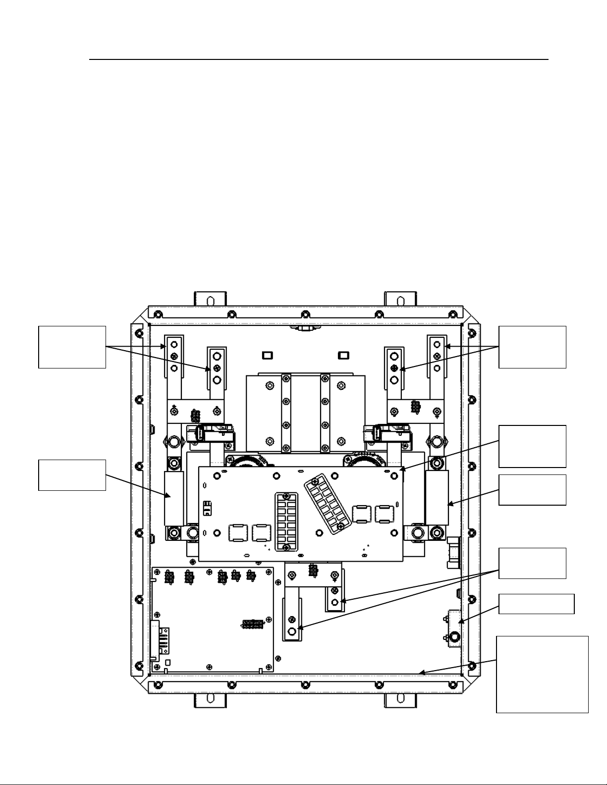
Internal components to be serviced by Vanner personnel only.
No routine maintenance of module is required.
Note: In the event an internal fuse is blown, it may be replaced by a qualified technician. Care
must be taken in following high voltage safety procedures prior to servicing and tightening
hardware to specified torque values.
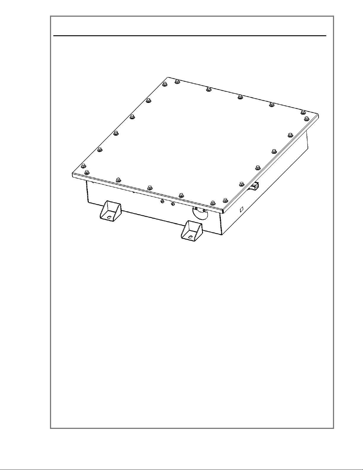
Environmental Considerations
IP55 Rated
Powder coated galvannealed steel enclosure provides protection against salt, fungus, dust, water,
fuel vapors and all fluids associated with commercial and off-highway vehicle operations.
Mounting Location
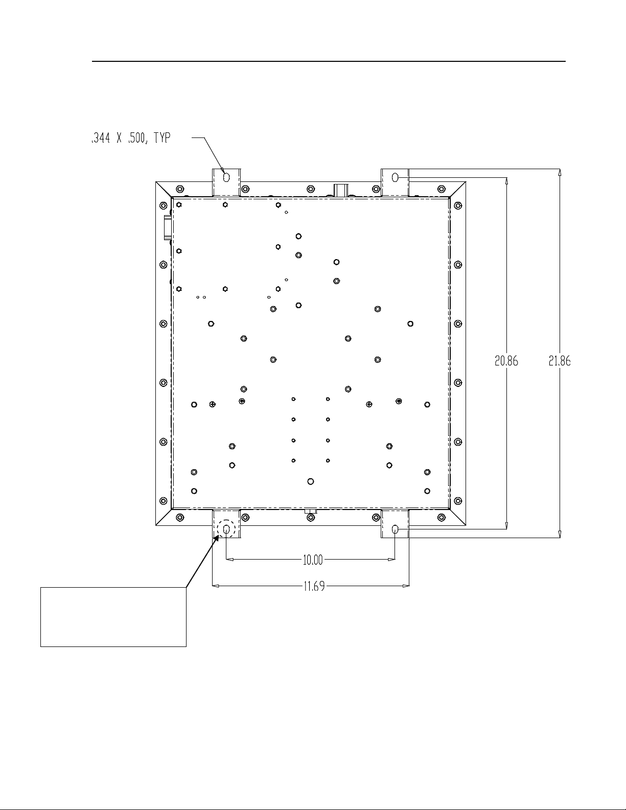
Mount on a flat surface (horizontal or vertical orientation) close to the high voltage batteries to
permit short cable runs.
Weight (lbs.)
30 (13.6kg)
Notes:
1. Channel 1 output is reserved for Vanner HBA's. Performance of the HVDM will be compromised if the load
connected to Channel 1 is not single or dual HBA's.
2. Channel 1 output is fused at 50A for Dual HBA's used in IAPIand IAPII applications.
3. Channel 2 output is fused at 80A for the VEPI (Vanner Exportable Power Inverter) used in IAPII applications.

VANNER
Incorporated Owner’s Manual
Vanner High Voltage Distribution Module OWNER’S MANUAL
5
Dimensional Specifications
(All Dimensions are in Inches)

VANNER
Incorporated OWNER’S MANUAL
Vanner High Voltage Distribution Module OWNER’S MANUAL
6
Mounting Specifications
(All Dimensions are in Inches)
1” Dia. masked area on
topside of mounting foot to
ground chassis to bus
frame. (CH1 Exit)

VANNER
Incorporated OWNER’S MANUAL
Vanner High Voltage Distribution Module OWNER’S MANUAL
7
Wiring Input/Output Specifications
Note: Deutsch part number suffix (**) is dependent on wire gage and insulation diameter.
CAN and I/O Connector
Deutsch #DT13-08PA
For mating connector use
Deutsch #DT06-08SA
For terminals (size 16) use
Deutsch #1062-16-**77
Pinout Definitions
1 - +24V Input
2 - Ignition Signal
3 - CAN Shield
4 - CAN Low
5 - CAN High
6 - Spare
7 - Command Signal (Active Low)
8 - Ground
HVIL Connector
Molex #194290033
For mating connector use
Molex #19418-0007 (14 - 16 AWG)
or Molex #19418-0008 (18 - 22 AWG)
For terminals use
Molex #19420-0009 (14 - 16 AWG)
or Molex #19420-0010 (18 - 22 AWG)
Note: HVIL connector is
mounted to this surface
for IAPImodels.

VANNER
Incorporated OWNER’S MANUAL
Vanner High Voltage Distribution Module OWNER’S MANUAL
8
CAN and I/O Definitions and Functionality
1. +24V Input
The +24V input powers the HVDM control board. The input shall come from the most convenient
termination point that is on the secondary side of the house battery main disconnect switch.
2. Ignition Signal
The ignition signal "wakes" the HVDM up. It may be +12V or +24V.
3. CAN Shield
This connection is used to make the shield on the CAN cable common. This is required for
electrical noise considerations in vehicle electrical systems.
4. CAN Low
This is the low signal connection for the vehicle’s CAN bus. The HVDM will communicate faults
to the vehicle’s electrical system controller via the CAN bus.
5. CAN High
This is the high signal connection for the vehicle’s CAN bus. The HVDM will communicate faults
to the vehicle’s electrical system controller via the CAN bus.
6. Spare
7. Command/Hardware Enable Signal
This is an active low signal that comes from the TCM (Transmission Control Module) of the hybrid
drive system. Reference Allison Transmission's Technical Document 192 for circuit requirements
for this input.
8. Ground
The ground input powers the HVDM control board. The input shall come from the most
convenient termination point tied to battery negative. Do not terminate to vehicle chassis.

VANNER
Incorporated OWNER’S MANUAL
Vanner High Voltage Distribution Module OWNER’S MANUAL
9
Wiring Input/Output Specifications Cont'd
* The HVDM is provisioned with two gland seal holes for Channel 1 and three gland seal holes for Channel 2.
The Channel 1 access points are for HBA’s only in IAPI or IAPII applications. The Channel 2 access points are
for pre-approved high voltage DC loads (IAPI) or a Vanner Exportable Power Inverter (VEPI) and pre-approved
high voltage DC load (IAPII).
Two studs per pole/channel are also provided to prevent installing two lugs on one stud.
EMI blanking plugs will be installed in any unused gland seal holes at the factory.
HV Input Conduit Access
1.85" Diameter Hole
Accommodates PG36 gland seal
Note: The HV input
conduit access hole is
located on this surface
for IAPImodels .
* Channel 1 and Channel 2 Outputs
1.12" Diameter Holes
Accommodate PG21 gland seals
Note: Channel 1 is reserved for HBA's only.
Channel 1
Channel 2
Channel 2.1

VANNER
Incorporated OWNER’S MANUAL
Vanner High Voltage Distribution Module OWNER’S MANUAL
10
Wiring Input/Output Specifications Cont'd
Positive Terminals and Fuse Terminals
The positive and fuse terminals are M8 x 1.25 studs
Tighten to a torque value of 100 lb-in (11 Nm)
Negative Terminals
The negative terminals are M10 x 1.5 studs
Tighten to a torque value of 150 lb-in (17 Nm)
Chassis Ground Terminal
The ground terminal is an M8 x 1.25 stud
Tighten to a torque value of 100 lb-in (11 Nm)
-
-
+
+
-
Channel 1
Output
+ and -
Channel 2
Output
+ and -
HV Input
+ and -
HVIL Switch
Channel 2
Fuse
Channel 1
Fuse
+
Note: HVIL
switch and
connector are
mounted to this
surface on IAPI
models.
Pre-charge
Relay
Board

VANNER
Incorporated OWNER’S MANUAL
Vanner High Voltage Distribution Module OWNER’S MANUAL
11
Operation
Distribution Module Start Up/Normal Operation
The following outlines the sequence of events that permit contact closure to power loads connected
to Channels 1 and 2 under normal conditions;
Standby Mode
1. HVDM is in "Standby" mode while awaiting +24V and ignition inputs from vehicle.
Controller Power Up
2. After receiving an ignition signal and +24V inputs, the HVDM controller will power up and
perform a low voltage self test.
Note: the low voltage must be between 18 - 32VDC.
Ready State
3. After successful completion of power up and low voltage self test, the HVDM will enter a
"Ready" state.
4. After entering the "Ready" state, the HVDM will wait for a hardware enable command, active
low, from the TCM.
5. After receiving the hardware enable signal, the HVDM will perform a high voltage self test.
Note: the high voltage must be between 400 - 800VDC.
6. After successfully completing the high voltage self test, the HVDM will wait for a CAN
message from the hybrid controller to proceed with pre-charging the connected load(s).
Contact Closure
7. Upon successful completion of pre-charging the load(s), contact closure will occur. The
load(s) are now connected to the high voltage battery/traction system.
The HVDM is designed to pre-charge a maximum capacitive load of 6,800µF in 2.5S.
8. After contact closure, the HVDM enters a "Contactor Closed" state.
Contact Opening
9. The contactors are opened via CAN message or removal of the hardware enable signal.
10. The passive discharge board will discharge the capacitive load(s) after contactor opening.

VANNER
Incorporated OWNER’S MANUAL
Vanner High Voltage Distribution Module OWNER’S MANUAL
12
Operation Cont'd
Distribution Module Abnormal Conditions
The following outlines conditions that will flag faults and the resultant impact on contactor
closure/opening. All conditions apply to both Channels 1 and 2. Reference Vanner's "High Voltage
Distribution Module DM1 Messages CAN Communication Specification" for more details about DM1
messaging.
Over Capacitance
If pre-charge fails within 1 second due to a load capacitance ≥ 6,800µF, a fault will be flagged
during the current key cycle. The fault will clear upon cycling the 24V off/on.
Short Circuit
If pre-charge fails within 100 milliseconds, a fault will be flagged during the current key cycle.
The fault will clear upon cycling the 24V off/on.
Welded Contactor
The HVDM is provisioned with welded contactor detection circuitry. If the HVDM detects one
or more welded contactors on the respective channel, the channel is disconnected for the
current key cycle.
Pre-Charge Lockout
If pre-charging load(s) is unsuccessful after 2 attempts, the channel will be disconnected from
the high voltage bus during the current key-cycle.
Non-Operational Relay
If the HVDM detects a non-operational relay, a fault will be flagged during the current key
cycle. The fault will clear upon cycling the 24V off/on.
High Voltage Out of Range (340 - 860VDC)
If the HVDM detects the high voltage is out of range, a fault is flagged.
High: If channel is not connected, it will not connect upon receiving turn-on command; If
channel is already connected, it will remain connected. The fault will clear when the input
voltage drops below 850V.
Low: If channel is not connected, it will not connect upon receiving turn-on command; If
channel is already connected, it will remain connected. The fault will clear when the input
voltage rises above 350V.
+24VDC Out of Range (18 - 32VDC)
If the HVDM detects the low input control voltage is out of range, a fault is flagged.
High: If channel is not connected, it will connect upon receiving turn-on command; If channel
is already connected, it will remain connected. The fault will clear when the input voltage
drops below 30.5V.
Low: If channel is not connected, it will connect upon receiving turn-on command; If channel
is already connected, it will remain connected. The fault will clear when the input voltage
rises above 19.5V.
Over Current (≥160A)
If an over current condition exists, a fault is flagged and the contactors opened during the
current key cycle. The fault will clear upon cycling the 24V off/on.

VANNER
Incorporated OWNER’S MANUAL
Vanner High Voltage Distribution Module OWNER’S MANUAL
13
Distribution Module Abnormal Conditions Cont'd
Temperature Out of Range (Loose Connection Detection)
The HVDM is provisioned with temperature sensors on the HV Input bus bars as well as
Channel 1 and Channel 2 output bus bars for the purpose of detecting loose mechanical
connections. If the HVDM detects an over-temperature condition (+95°C), a fault is flagged
and both channels are disconnected for the current key cycle.
Current Sensor Data Erratic
The HVDM is provisioned with automotive style sensors for measuring current on both output
channels. If the signal voltage from a sensor to the control board falls outside of the 2.5V -
5V range, a fault will be flagged. If channel is not connected, it will connect upon receiving
turn-on command; If channel is already connected, it will remain connected. The fault will
clear when the signal voltage falls within the 2.5V - 5V range.
Loss of CAN Command
If the HVDM loses the CAN turn on command from the HCM (Hybrid Control Module), a fault
is flagged. If channel is not connected, it will connect upon receiving turn-on command; If
channel is already connected, it will remain connected. The fault will clear when new CAN
command is received continuously.

VANNER
Incorporated OWNER’S MANUAL
Vanner High Voltage Distribution Module OWNER’S MANUAL
14
Installation Instructions
These symbols are used to note procedures that if not closely followed could lead to loss of life or
damage to equipment or property due to electrocution.
Electrocution hazard exists
Fire hazard exists
A potentially dangerous condition
Explosive hazard exists
Corrosive hazard exists
Do not exceed the specified torque value of 100 lb-in (11Nm) when connecting cables to the
positive (+600V) input and output studs during installation of the HVDM. Torque values higher than
specified may damage the product, reduce performance, and/or create hazardous conditions. Products
damaged by improper torque are not covered by the warranty.
Do not exceed the specified torque value of 150 lb-in (17Nm) when connecting cables to the
negative input and output terminal posts (-600V) during installation of the HVDM. Torque values higher
than specified may damage the product, reduce performance, and/or create hazardous conditions.
Products damaged by improper torque are not covered by the warranty.
Do not connect more than one conductor per terminal post on Vanner HVDM. Multiple wires
and cables may overstress internal components, resulting in poor performance or creating hazardous
conditions. Products damaged by the installation of multiple conductors per post are not covered by the
warranty.
Caution: This equipment contains components that may produce
arcs/sparks during a fault condition. To prevent fire or explosion, compartments containing batteries or
flammable materials must be properly ventilated. Safety goggles should always be worn when working
near batteries.
Mounting Location –The HVDM must be mounted on a flat horizontal or vertical surface suitable
for support during application. Do not mount in a zero-clearance compartment that may result in
overheating. Locate the HVDM so that contact by unauthorized personnel is unlikely.

VANNER
Incorporated OWNER’S MANUAL
Vanner High Voltage Distribution Module OWNER’S MANUAL
15
Installation Instructions Cont'd
Environmental Protection
Your HVDM has been designed to withstand intermittent exposure to rain, moisture and direct
pressure spray. However, continual exposure to rain and/or direct pressure spray may reduce the
serviceable life of the unit. Any damage due to water contamination is covered by Vanner only
through the terms of the factory warranty.
Wiring
After mounting the HVDM as outlined above, the shielded high voltage input and Channel 1/Channel
2 output wires may be installed. Reference the "Wiring Input/Output Definitions" section of this
manual for proper identification/location of the input and output studs.
Note: The HVDM positive and negative studs are staggered and are different sizes to minimize the
risk of reverse polarity connections.
Ensure proper clearances are provided when routing wires within the HVDM enclosure to eliminate
the risk of chafing/abrading the insulation. If proper clearances aren't provided, a short circuit could
occur causing severe damage.
The I/O and HVIL wiring may be installed upon completion of installing the high voltage wiring.
Reference the "Wiring Input/Output Definitions" section of this manual for proper identification of the
pinouts for the I/O and HVIL connectors.
Wire Sizes
The shielded cables connecting the HVDM to the hybrid traction battery shall be appropriately sized
based on the current limiting device between the input and battery.
The shielded cables connecting Channel 1 and Channel 2 outputs to their respective loads shall be
appropriately sized based on the factory installed fuses. 8 AWG wire is recommended as a minimum
for 35A and 50A fuses. 4 AWG wire is recommended as a minimum for an 80A fuse.
Note: The above wire sizes are for recommendation only. Wire sizing charts should be consulted by
the installer to ensure voltage drop and temperature de-rating factors are taken into consideration.

VANNER
Incorporated OWNER’S MANUAL
Vanner High Voltage Distribution Module OWNER’S MANUAL
16
Typical IAPIDiagram for Transit Bus
TRACTION DRIVE BATTERIES
HVIL
HIGH VOLTAGE
CHANNEL 2
A/C OR A/C'S
HVIL
HIGH VOLTAGE DISTRIBUTION MODULE (HVDM)
HVIL
TRACTION DRIVE INVERTER
HVIL
HIGH VOLTAGE
CHANNEL 1
HBA OR HBA'S
HVIL
Note: This is a basic block diagram of the major components and HVIL circuit comprising an IAPI
system.

VANNER
Incorporated OWNER’S MANUAL
Vanner High Voltage Distribution Module OWNER’S MANUAL
17
Typical IAPII Diagram for Transit Bus
230V
3PH AC
TRACTION DRIVE BATTERIES
HIGH VOLTAGE
CHANNEL 2
VEPI
(VANNER
EXPORTABLE
POWER INVERTER)
HVIL
HIGH VOLTAGE DISTRIBUTION MODULE (HVDM)
HVIL
TRACTION DRIVE INVERTER
HVIL
HIGH VOLTAGE
CHANNEL 1
HBA OR HBA'S
HVIL
HVIL
AC DISTRIBUTION
HVILHVIL
ELECTRIC AIR
CONDITIONER
ELECTRIC AIR
COMPRESSOR
HVDC ACCESSORY
HVIL
HVIL
Note: This is a basic block diagram of the major components and HVIL circuit comprising an IAPII
system.

VANNER
Incorporated OWNER’S MANUAL
Vanner High Voltage Distribution Module OWNER’S MANUAL
18
Testing and Troubleshooting
CAUTION
Servicing of electrical systems should only be performed by trained and qualified technical personnel.
Equipment Required
VoltMeter having 0.01 volt resolution. (Fluke Model 87 Multimeter recommended).
Clamp-on current meter (Fluke Model 36 Clamp-on Meter recommended).
Optional: Vanner laptop provisioned with Vanner Dashboard software
USB to CAN adapter module. (PEAK System’s PCAN-USB IPEH-002021)
Note: There are kits available for purchase that include Vanner's Dashboard software, a USB to CAN
adapter module and a harness to connect to the vehicle's CAN network. Please contact Vanner's
inside sales department for the appropriate kit part number for your application.
Vanner Repair Service
Vanner offers a quick turn-around factory repair service. Send the unit to the address on last page with a
note instructing us to repair it. Include your name, phone number, shipping address (not a P.O. Box
Number), and your purchase order number.

VANNER
Incorporated OWNER’S MANUAL
Vanner High Voltage Distribution Module OWNER’S MANUAL
19
Test Procedure for HVDM
HVDM Test Procedure:
Note: Although not required, using Vanner's Dashboard Interface software for monitoring the status of the
HVDM is highly recommended. The Dashboard software provides a graphical representation of the
states of the Channel 1 and 2 contactors as well as the high voltage and current of each channel.
1. Field-test the HVDM while fully connected to the vehicles high voltage batteries and the Channel 1
and Channel 2 loads.
2. Ensure the chassis cover is installed and all fasteners are in place. The HVDM is provisioned with an
HVIL switch, therefore if the cover is not installed properly, the ESS contactors will not close.
3. The low voltage battery must measure between 18 and 32 volts. If the low voltage battery is below
18 volts, apply a 24 volt battery charger to the batteries.
4. The high voltage battery must measure between 400 and 800 volts for the HVDM to start properly.
5. Monitor the HVDM status via laptop provisioned with the Dashboard software.
6. The HVDM will enter the "Standby" mode when the low voltage battery master disconnect switch is
closed.
7. Start the vehicle normally.
8. Provided the operational conditions outlined above are met, the HVDM will enter a "Ready" state
upon receiving an ignition signal and await a hardware "Enable" command, active low, from the TCM.
9. After receiving the "Enable" command from the TCM, the pre-charge sequence will begin once the
HVDM receives a "Connect" CAN message from the HCM.
10. Upon successfully pre-charging the loads on Channel 1 and/or Channel 2, the respective contactor(s)
will close.
11. The contactor status is graphically displayed on the Dashboard but closure can also be verified by
observing the voltage and current values. Note: The current and voltage values are measured on the
secondary side of the contactors.
12. If the Dashboard software isn't being utilized, contact closure can be verified by observing the
operational status of the loads connected to Channel 1 and/or Channel 2.
13. Upon successful contact closure, the HVDM enters an "Open Pending" state. The contactors are
opened via the CAN "Disconnect" message or removal of the hardware enable signal.
Note: The high voltage terminals are inaccessible for measurement with a meter. A high voltage interlock
circuit is implemented for safety purposes to prevent an accidental and potentially lethal shock to service
personnel. The high voltage input and Channel 1 and Channel 2 outputs can only be read via the
Dashboard software.

VANNER
Incorporated OWNER’S MANUAL
Vanner High Voltage Distribution Module OWNER’S MANUAL
20
HVDM Dashboard Screenshots
Figure 1: HVDM in "Ready" state after receiving ignition signal
Figure 2: Hardware "Enable" signal from TCM activated. Note contactors are still open.
Channel 1 and Channel 2 voltages,
currents and bus bar temperatures
displayed in this section
Graphical representations of
Channel 1 and Channel 2 contactor
states in this section
HVDM and contactor status
information displayed in this section
Ignition, enable and CAN Control
Command information displayed in
this section
Note status change to "Enabled"
Note "Hardware Enable" icon is lit
This manual suits for next models
11
Table of contents