manuals.online logo
Brands
  1. Home
  2. •
  3. Brands
  4. •
  5. GHM Greisinger
  6. •
  7. Transducer
  8. •
  9. GHM Greisinger GRMU2000 MP User manual

GHM Greisinger GRMU2000 MP User manual

T02.0.1X.6C-01 page 1of 3
Operating Manual for Redox-Measuring transducer
GRMU2000 MP
Specification:
Measuring range: -2000 to 2000mV or refer to type plate
Accuracy: ±0,2% (at nominal temperature)
Output signal: refer to type plate
Connection: 4 - 20 mA (2-wire)
Voltage (3- resp. 4-wire)
Electric isolation: input electrically isolated
Auxiliary energy: (supply voltage) Uv = 12 - 30 V DC (4-20mA)
Uv = 18 - 30 V DC (0-10V)
or refer to type plate
Reverse voltage protection: 50V permanent
Perm. impedance (at 4-20mA):RA(Ohm) < ( (Uv - 12V) / 0.02A )
Example: for Uv = 18V: RA< (18V - 12V) / 0.02A => RA< 300 Ohm
Permissible load(at 0-...V):RL(Ohm) > 3000 Ohm
Electrode: any Redox-Electrode of our program is suitable.
(electrode not included in scope of supply!)
Input resistance: 1012 Ohm
Electrode socket: Cinch-socket (standard), optionally available with BNC- and DIN-socket
Display: none
Optional display: approx. 10 mm high, 3½-digit LCD-display
Nominal temperature: 25°C
Operating temperature: 0 to 50°C
Relative humidity: 0 to 95 % r.F. (non-condensing)
Storage temperature: -20 to 85°C
Housing: ABS (IP65 - with the exception of electrode)
Dimensions: 82 x 80 x 55 mm (without elbow-type plug and sensor sockets)
Mounting: With fixing holes for wall mounting (in housing - accessible after cover has been
removed).
Mounting distance: 50 x 70mm, max. shaft diameter of mounting screws is 4 mm.
Electric connection: elbow-type plug conforming to DIN 43650 (IP65),
max. wire cross section: 1.5 mm², wire/cable diamter from 4.5 to 7 mm
EMC: The
GRMU2000MP corresponds to the essential protection ratings established in the Regulations
of the Council for the Approximation of Legislation for the member countries regarding
electromagnetic compatibility (89/336/EWG). In accordance with EN50081-1 and EN50082-1
Additional error: <1%
GREISINGER electronic GmbH
T02.0.1X.6C-01 page 2of 3
Assignment of elbow-type plug:
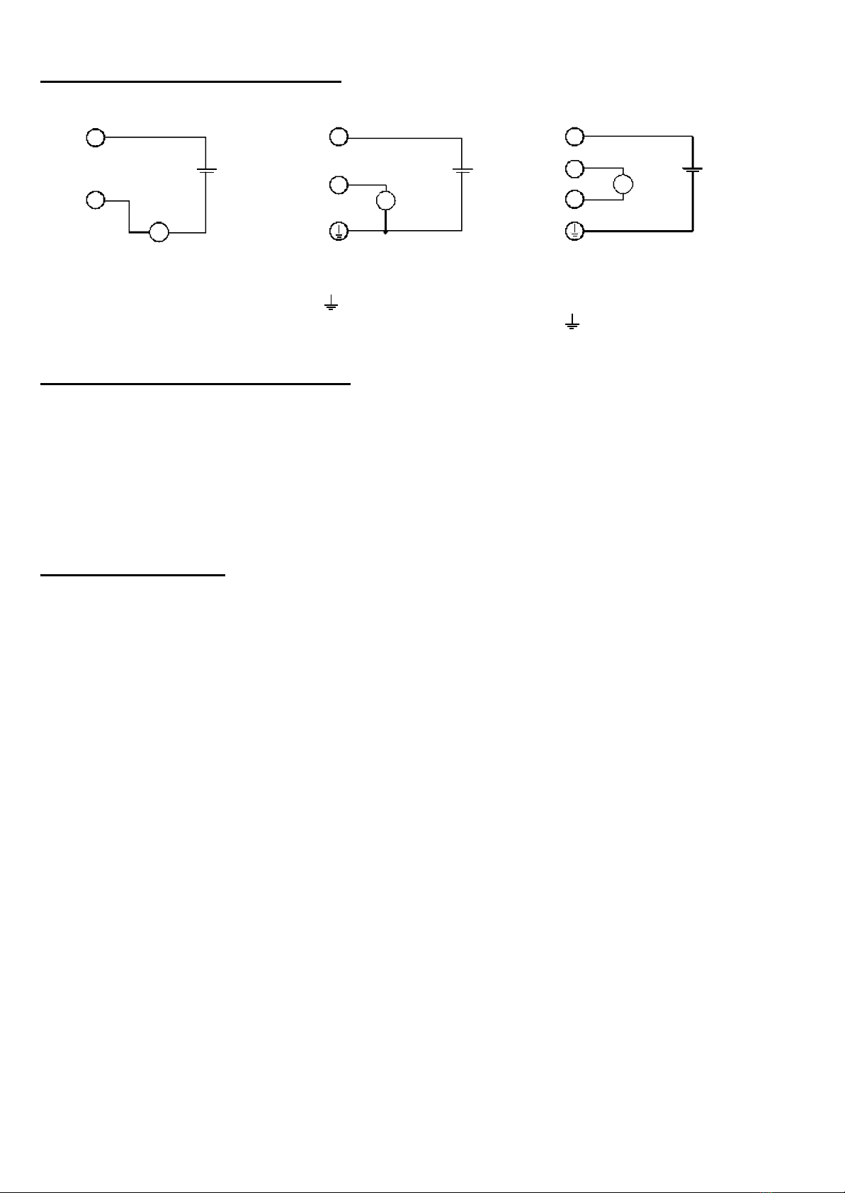
2-wire connection (4-20mA) 3-wire connection (voltage) 4- wire connection (voltage)
1= supply voltage +Uv 1= signal + 1= signal +
2= GND / signal 3= supply voltage +Uv 2= signal -
=supply voltage -Uv 3= supply voltage +Uv
signal - = supply voltage -Uv
General installation instructions:
To mount the connection cable (2-, 3-, or 4-wire depending on type of device) the angle plug screw has to be loosened
and the coupling insert has to be removed by means of a screw driver at the position indicated (arrow).
Pull out connection cable through PG glanding and connect to the loose coupling insert as described in the wiring
diagram. Replace loose coupling insert onto the pins at the transmitter housing and turn cover cap with PG glanding in
the direction desired till it snaps on (4 different starting positions at 90° intervals). Re-tighten the screw at the angle plug.
Before connecting to supply voltage, ensure that a working electrode is connected.
Safety instructions:
This device has been designed and tested in accordance with the safety regulations for electronic devices.
However, its trouble-free operation and reliability cannot be guaranteed unless the standard safety measures and special
safety advises given in this manual will be adhered to when using the device.
1. Trouble-free operation and reliability of the device can only be guaranteed if the device is not subjected to any other
climatic conditions than those stated under "Specification". If the device is transported from a cold to a warm
environment condensation may cause in a failure of the function. In such a case make sure the device temperature
has adjusted to the ambient temperature before trying a new start-up.
2. General instructions and safety regulations for electric, light and heavy current plants, including domestic safety
regulations (e.g. VDE), have to be observed.
3. If device is to be connected to other devices (e.g. via PC) the circuitry has to be designed most carefully. Internal
connection in third party devices (e.g. connection GND and earth) may result in not-permissible voltages impairing or
destroying the device or another device connected.
4. If there is a risk whatsoever involved in running it, the device has to be switched off immediately and to be marked
accordingly to avoid re-starting.
Operator safety may be a risk if:
- there is visible damage to the device
- the device is not working as specified
- the device has been stored under unsuitable conditions for a longer time.
In case of doubt, please return device to manufacturer for repair or maintenance.
1
2
A
Uv V
3
Uv1VUv
3
1
2
T02.0.1X.6C-01 page 3of 3
Important!! redox - electrodes are very sensitive. Please read manual of the electrode carefully before usage.
Error and System Messages [only with option display ]
Display Description Posible fault cause Remedy
FE 1 Measuring values
exceeding measuring
range
redox value is out of the
transducers measuring range Replace electrode.
Redox electrode defective Replace electrode.
FE 2 Measuring values below
measuring range transducer defective Return to manufacturer for repair
FE 7 System fault Error in transducer Disconnect transducer from supply and
reconnect. If error remains: Return to
manufacturer for repair .
Segment test The transducer performs a display test for 2 seconds after switch on. After
that it will change the the display of the measuring.
redox electrode not connected Check the connection and cable.
8.8.8.8 Input signal is not valid Permissible input range is
exceeded
Check if not a wrong electrode (ph or
others) is connected.
Replace electrode.

Popular Transducer manuals by other brands

Shinkawa FK-452F instruction manual

Shinkawa

Shinkawa FK-452F instruction manual

Setra Systems 355X Series Operating & installation instructions

Setra Systems

Setra Systems 355X Series Operating & installation instructions

Emerson Fisher 846 Instruction manual supplement

Emerson

Emerson Fisher 846 Instruction manual supplement

Veris T-VER-H970-200 Connection instructions

Veris

Veris T-VER-H970-200 Connection instructions

HBM C2 Series Mounting instructions

HBM

HBM C2 Series Mounting instructions

S+S Regeltechnik PREMASREG 711 VA LCD Series Operating Instructions, Mounting & Installation

S+S Regeltechnik

S+S Regeltechnik PREMASREG 711 VA LCD Series Operating Instructions, Mounting & Installation

Simrad ES120-7DD -  REV B datasheet

Simrad

Simrad ES120-7DD - REV B datasheet

Campbell CS451 instruction manual

Campbell

Campbell CS451 instruction manual

WIKA Mensor CPT6030 operating instructions

WIKA

WIKA Mensor CPT6030 operating instructions

feedback TK2942 manual

feedback

feedback TK2942 manual

cec 4-137 quick start guide

cec

cec 4-137 quick start guide

ELTRA EAL installation instructions

ELTRA

ELTRA EAL installation instructions

B-K Medical 8808e user guide

B-K Medical

B-K Medical 8808e user guide

red lion CTL12S manual

red lion

red lion CTL12S manual

Setra Systems 278 installation guide

Setra Systems

Setra Systems 278 installation guide

TR-Electronic LMRI-46 200 PB manual

TR-Electronic

TR-Electronic LMRI-46 200 PB manual

Raymarine Realvision RV-220P installation instructions

Raymarine

Raymarine Realvision RV-220P installation instructions

Setra Systems 470 manual

Setra Systems

Setra Systems 470 manual

manuals.online logo
manuals.online logoBrands
  • About & Mission
  • Contact us
  • Privacy Policy
  • Terms and Conditions

Copyright 2025 Manuals.Online. All Rights Reserved.