GHM-Martens GS125 User manual

English
Operating manual
Limit switch
GS125
Ventures / brands of
GHM
www.ghm-messtechnik.de
Keep for future reference.

GHM Messtechnik GmbH
–
Location
Martens
Kiebitzh rn 18 ● 22885 Barsbüttel ● Germany
Phone +49-40-670 73-0 ● Fax -288
www.ghm-messtechnik.de ● [email protected]
2
able of contents Page
1. Intended use (areas of application) ................................................................. 3
1.1 Safety signs and symbols ........................................................................ 3
1.2 Safety instructions .................................................................................... 4
1.3 Product liability and warranty ................................................................... 4
1.4 Standards and directives .......................................................................... 4
2. Product description .......................................................................................... 5
2.1. Scope of delivery ...................................................................................... 5
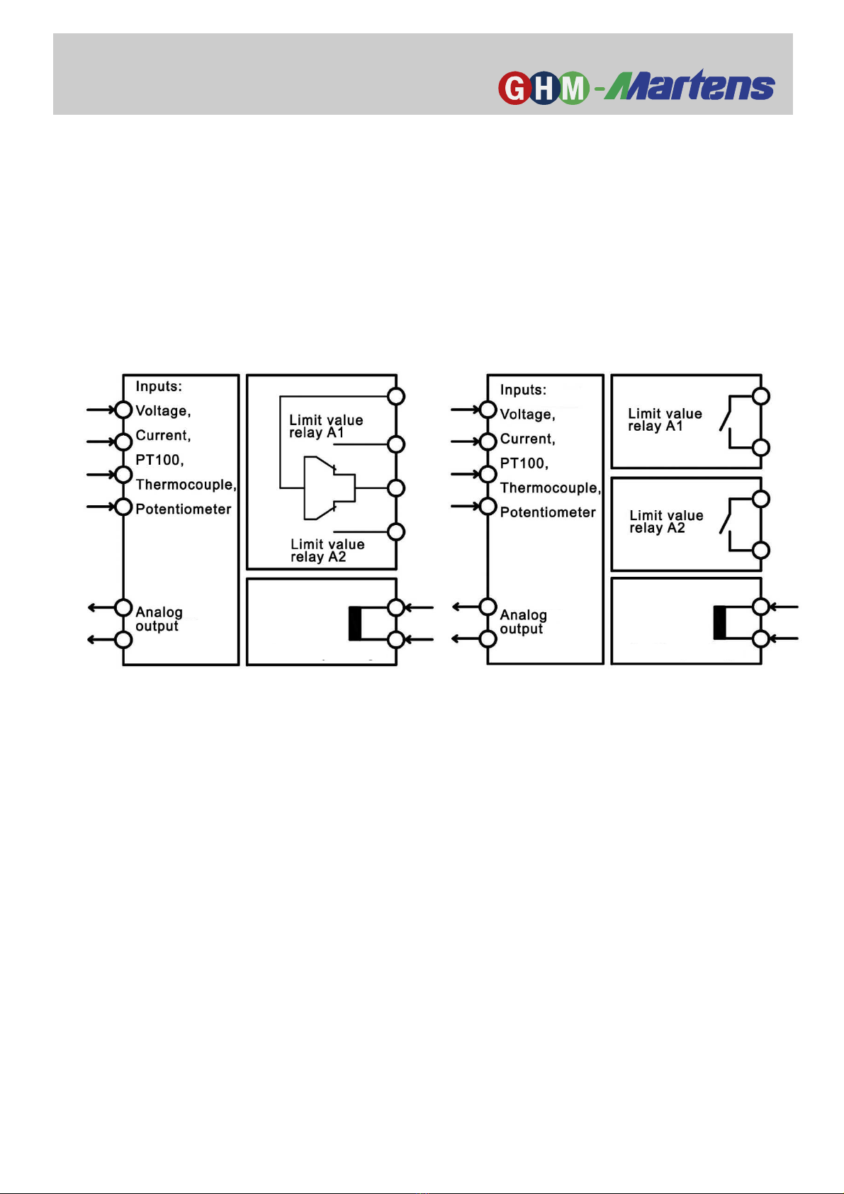
2.2. Functional principle .................................................................................. 6
2.3. Connection diagram ................................................................................. 7
2.4. Limit value contacts .................................................................................. 8
2.5. PowerRail ................................................................................................. 9
2.6. Positioning of the adhesive labels with measuring units ........................ 10
2.7. Type plate .............................................................................................. 10
3. Assembly and installation .............................................................................. 11
3.1. Mechanical assembly ............................................................................. 11
3.2. Electrical installation ............................................................................... 11
4. Controls and functional description ............................................................. 12
5. Commissioning, maintenance and service .................................................. 14
5.1 Commissioning ....................................................................................... 14
5.2 Maintenance ........................................................................................... 14
5.3 Service ................................................................................................... 14
6. echnical data ................................................................................................. 15
6.1 Mechanical design / dimensions ............................................................ 17
7. Order code ....................................................................................................... 18
8. Device transport and storage ........................................................................ 18
9. Return to manufacturer .................................................................................. 19
10. Disposal ........................................................................................................... 19
11 Imprint .............................................................................................................. 19
12. Certificate of conformity ................................................................................. 20

GHM Messtechnik GmbH
–
Location
Martens
Kiebitzh rn 18 ● 22885 Barsbüttel ● Germany
Phone +49-40-670 73-0 ● Fax -288
www.ghm-messtechnik.de ● [email protected]
3
1. Intended use (areas of application)
Refer to the chapter 'Product description' for detailed specifications for
the area of application.
The operational safety of the device is only assured when used as in-
tended in accordance with the specifications in the operating manual.
Intervention beyond the actions described in the operating manual may only be car-
ried out by personnel authorised by the manufacturer for safety and warranty rea-
sons. Conversions or modifications made on one's own authority are expressly pro-
hibited.
Application-specific dangers can emanate from this device when used improperly or
not as intended.
Application-specific dangers can emanate from this device when used
improperly or not as intended.
The device is not intended for use in explosion-prone areas.
General safety instructions, use
This operating manual must be kept in a location such that qualified personnel can
refer to it at all times.
Any processes described in this operating manual may only be carried out by
trained, qualified personnel who are authorised by the owner and wearing protec-
tive clothing. All rights reserved.
1.1 Safety signs and symbols
Warning notices are identified in this document as described under Table 1:
Warning! This symbol warns of imminent danger which can result
in death, severe bodily injury, or severe property damage in case
of non-observance.
Attention! This symbol warns of potential dangers or harmful sit-
uations which can cause damage to the device or to the envi-
ronment in case of non-observance.
Note! This symbol indicates processes which can have a direct
influence on operation or can trigger an unforeseen reaction in
case of non-observance.
Danger

GHM Messtechnik GmbH
–
Location
Martens
Kiebitzh rn 18 ● 22885 Barsbüttel ● Germany
Phone +49-40-670 73-0 ● Fax -288
www.ghm-messtechnik.de ● [email protected]
4
1.2 Safety instructions
Read the product description before commissioning the device. Ensure that there
are no limitations for use of the product for the relevant applications.
The owner is responsible for ensuring the fault-free operation of the
device. The owner is obligated to ensure compliance and to observe
the required work and safety measures of the current applicable regu-
lations for the entire duration of use.
1.3 Product liability and warranty
Exclusion of liability:
The contents of the operating manual have been checked to ensure conformity with
the described device. However, deviations cannot be entirely ruled out. Therefore,
we cannot assume any guarantee for complete conformity. The specifications in
this document are checked regularly and any necessary corrections are incorpo-
rated into subsequent versions. This document is subject to technical changes. In
addition, all claims are based on the valid 'Standard Terms for the Supply of Prod-
ucts and Services of the Electrical Industry'.
GHM Messtechnik cannot inspect or repair any devices without the
required form having been filled in completely (see chapter 'Returns').
1.4 Standards and directives
Low-voltage Directive 2014/35/EU
Testing standard 60664-1: 2007
EMC Directive 2014/30/EU
Testing standard EN 61326-1: 2013
RoHS Directive 2011/65/EU
Testing standard EN50581: 2012
Functional safety
Testing standards EN61508-1: 2010
(Issue years for testing standards belong to german versions)
DANGER

GHM Messtechnik GmbH
–
Location
Martens
Kiebitzh rn 18 ● 22885 Barsbüttel ● Germany
Phone +49-40-670 73-0 ● Fax -288
www.ghm-messtechnik.de ● [email protected]
5
2. Product description
Limit switches of the series GS125 are used in switch cabinets for process monitoring
or even for simple process regulation. Temperatures and derived signals such as volt-
age, current and resistance can be used as control signals. In the process, 1 or 2 limit
values can be monitored. With the universal configurability of the measuring inputs, the
need to stock multiple parts for various applications is reduced. The housing width of
only 12.5mm allows space-saving installation in the switch cabinet. The limit value ad-
justment scales which are illuminated red or green depending on the switching status
also enable operation in dark environments.
2.1. Scope of delivery
• GS125
• 24 transparent labels with measurement units and scale assignment
• This operating manual
• Additional documents, if applicable
2 relay contacts in universal circuit 2 potential-free NO contacts
Supply volt
a
ge
Supply volt
a
ge

GHM Messtechnik GmbH
–
Location
Martens
Kiebitzh rn 18 ● 22885 Barsbüttel ● Germany
Phone +49-40-670 73-0 ● Fax -288
www.ghm-messtechnik.de ● [email protected]
6
2.2. Functional principle
One or two relays may be switched depending on the measurement at the device
input.
Limit values can be adjusted with illuminated adjustment wheels. When the limit
values are reached (depending on the input signal), relays are switched.
The relay status is indicated by a colour change in the scales of the adjustment
wheels.
The switching behaviour of the relay can be specified as a minimum or maximum
contact.
Device configuration will be done via DIP switches.
The relay is designed as a changeover contact for single-channel devices.
Two-channel devices can be optionally supplied with a universal connection of the
relay contacts or with two potential-free NO contacts.
The universal connection enables use of the device with 2 independent NO con-
tacts or in window range monitoring in which the two contact relays can be open or
closed within the target range.
The application is selected with the wiring of the outer connection terminals.
A device version is available with analog output that reproduces the respective in-
put signal to 4-20mA. The analog output is not galvanically isolated from the input
signal!
The device may be supplied in a wide range between 20..125V DC or 20..253V AC.
A low cost version with 24V DC power supply is available.
Another version allows a 24V power supply via a mounting rail bus (Power Rail)
Twenty-four transparent adhesive labels are provided for assigning the unit of
measure for the scale labelling. They can be affixed between the adjustment
wheels on the front panel, depending on requirements.

GHM Messtechnik GmbH
–
Location
Martens
Kiebitzh rn 18 ● 22885 Barsbüttel ● Germany
Phone +49-40-670 73-0 ● Fax -288
www.ghm-messtechnik.de ● [email protected]
7
2.3. Connection diagram
Input signals should be connected via separate 2 or 3 core cables.
Grounded leads may cause problems with the not galvanical isolated
analog true value output.
rue value output
Multisignal inputs

GHM Messtechnik GmbH
–
Location
Martens
Kiebitzh rn 18 ● 22885 Barsbüttel ● Germany
Phone +49-40-670 73-0 ● Fax -288
www.ghm-messtechnik.de ● [email protected]
8
2.4. Limit value contacts

GHM Messtechnik GmbH
–
Location
Martens
Kiebitzh rn 18 ● 22885 Barsbüttel ● Germany
Phone +49-40-670 73-0 ● Fax -288
www.ghm-messtechnik.de ● [email protected]
9
2.5. PowerRail
The supply of multiple devices can be combined and simplified via a bus system
in the carrier rail (TS35).
An equivalent version is available for the entire LP series of GHM carrier rail
devices in 12.5mm wide housing.
Before mounting the device to be supplied, a series-compatible bus adapter must
be connected on the carrier rail.
For this purpose, an adapter piece is required for each device. The supply of the
bus then takes place via a plug-in terminal strip.
In the device version GS125LP provided for this purpose, the supply terminals 11
and 12 on the upper side of the device are omitted.

GHM Messtechnik GmbH
–
Location
Martens
Kiebitzh rn 18 ● 22885 Barsbüttel ● Germany
Phone +49-40-670 73-0 ● Fax -288
www.ghm-messtechnik.de ● [email protected]
10
2.6. Positioning of the adhesive labels with measuring units
2.7. ype plate
The type plate contains the most important identification data
● Type and article designation
● Technical data
● Serial number / bar code
Fig. 3: Type plate

GHM Messtechnik GmbH
–
Location
Martens
Kiebitzh rn 18 ● 22885 Barsbüttel ● Germany
Phone +49-40-670 73-0 ● Fax -288
www.ghm-messtechnik.de ● [email protected]
11
3. Assembly and installation
3.1. Mechanical assembly
Mounting rail assembly TS35, DIN EN 60715
Gapless installation of several devices is only permitted with horizontally installed
mounting rails.
3.2. Electrical installation
The device may only be installed by an electrician. Compliance with
the national and international regulations for installation of electrical
and electronic systems applicable in the respective country of use is
mandatory.
Voltage supply in accordance with DIN EN60664-1, SELV, PELV.
Observe the connection diagram for installation of the inputs and outputs.
The supply voltage is connected to pins 11 and 12 of the plug-in terminal strip.
Terminals 41, 42, 51 and 52 are provided for sensor connection
Terminals 21, 22, 31 and 32 are provided for the relay output
Terminals 61 and 62 are provided for the actual value output
Fig. 4
DANGER

GHM Messtechnik GmbH
–
Location
Martens
Kiebitzh rn 18 ● 22885 Barsbüttel ● Germany
Phone +49-40-670 73-0 ● Fax -288
www.ghm-messtechnik.de ● [email protected]
12
4. Controls and functional description
Adjustment wheel (Channel 1)
illuminated red / green
Adjustment wheel (Channel 2)
illuminated red / green
DIP-Switches
Selection of the measuring range takes place with DIP switches 1-4:
current / voltage, potentiometer, Pt100, thermocouple
The black fields symbolize the position of
the DIP switches
(When voltage and current are injected simultaneously the result is an addition of the input related signals)
The respective limit values can be adjusted with wheels A1 and A2.
The illuminated scales serve as an operating indicator.
When a limit value relay is not active, the adjustment wheel scale illuminates
green.
When a limit value relay is active, the adjustment wheel scale illuminates red.

GHM Messtechnik GmbH
–
Location
Martens
Kiebitzh rn 18 ● 22885 Barsbüttel ● Germany
Phone +49-40-670 73-0 ● Fax -288
www.ghm-messtechnik.de ● [email protected]
13
The switching behaviour of the relays can be determined with DIP switches 5 and 6:
max max: The relay is activated when the input signal is equal or above the limit
min min: The relay is activated when the input signal is equal or below the limt
For applications with functional safety (SIL2), the device must be configured that
the relay is deactivated in the event of an error!
With use of the analog output for SIL2, the evaluation unit must be configured that
values > 21 mA and values < 1 mA are recognized as errors.
Sensor break and sensor short-circuit
In the measuring ranges with Pt100 sensors, breaks and short-circuits are moni-
tored.
In this case, the relays are deactivated and the scale lighting blinks red.
The analog output drops to approx. 0mA.

GHM Messtechnik GmbH
–
Location
Martens
Kiebitzh rn 18 ● 22885 Barsbüttel ● Germany
Phone +49-40-670 73-0 ● Fax -288
www.ghm-messtechnik.de ● [email protected]
14
5. Commissioning, maintenance and service
5.1 Commissioning
1. Ensure that the connections have been made as indicated in the connection di-
agram and the supply voltage is correct.
2. Make sure that the terminals are firmly screwed in.
3. After switching on the power, check to ensure the correct device function.
5.2 Maintenance
Housing:
No cleaning or maintenance is required when operated as intended.
5.3 Service
Service of the device is only possible in the factory.

GHM Messtechnik GmbH
–
Location
Martens
Kiebitzh rn 18 ● 22885 Barsbüttel ● Germany
Phone +49-40-670 73-0 ● Fax -288
www.ghm-messtechnik.de ● [email protected]
15
6. echnical data
Wide-range power supply
Supply Voltage : 20..125 V DC and
20..250V AC, (47..63Hz), max. 1.5W
24 V power supply
Supply voltage : 24 V DC +/-15%, max. 1.5W
Combined data
Rated voltage : 253V AC (acc. to EN60664-1; pollution degree 2,
overvoltage category II)
Test voltage : 3kV AC between input / relay output / supply voltage
Working temperature : -10..60 °C
Storage temperature : -20..80 °C
Air humidity : 10..90 % (no condensation)
EMC : acc. to EN61326-1
Measurement inputs
Voltage : 0/2..10 V, Ri approx. 20 kΩ
Current : 0/4..20 mA, Ri approx. 60 Ω
Pt100 : Linearised, measuring current approx. 1.6 mA
Relays are deactivated if there is a sensor
break or short circuit
Thermocouple : Linearised with reference junction compensation
(optional without internal compensation)
Resistance : Potentiometer (3-wire), rated value 500 Ω - 20 kΩ internal
reference voltage approx. 1.5 V
Relay outputs
Switching voltage : <250 V AC <2 A <500 VA
<125 V DC <0.2 A <25 W
< 30 V DC <2 A <60 W
Switching frequency : max. 5 Hz
Switching hysteresis : approx. 1%
Limit value adjustment : Scale precision: 2 %
Analog output : 4..20 mA, max. burden 120 Ω
(burden failure at 120 Ω max. 0,1%)
No galvanic isolation from the input signal

GHM Messtechnik GmbH
–
Location
Martens
Kiebitzh rn 18 ● 22885 Barsbüttel ● Germany
Phone +49-40-670 73-0 ● Fax -288
www.ghm-messtechnik.de ● [email protected]
16
Input signal Basic precision actual value output Temperature deviation *)
0/2..10V 0.2% 0.004%/K
0/4..20mA 0.2% 0.004%/K
Potentiometer 1.0% 0.007%/K
Pt100 -50.. 50°C 0.5% 0.03%/K
Pt100 0.. 50°C 0.9% 0.04%/K
Pt100 0..100°C 0.5% 0.03%/K
Pt100 0..150°C 0.2% 0.02%/K
Pt100 0..200°C 0.4% 0.02%/K
Pt100 0..300°C 0.3% 0.01%/K
Pt100 0..500°C 0.2% 0.007%/K
FeCuNi 0..250°C 1.0% 0.04%/K
FeCuNi 0..500°C 0.5% 0.03%/K
NiCrNi 0..500°C 0.5% 0.04%/K
NiCrNi 0..750°C 0.4% 0.03%/K
NiCrNi 0..1000°C 0.3% 0.02%/K
PtRhPt 0..1500°C 1.0% 0.04%/K
*) Measurement deviation depending on the environmental temperature in the switch cabinet (-10 - +60°C)
Casing
Dimensions (WxDxH) : 12.5 x 115 x 108 mm
Material : PA6.6, light grey, flammability class V0 (UL94)
Weight : 120 g
Protection rating : IP20
Screw terminal connection : 0.2..2.5 mm², AWG 24 - 14, removable, coded
Push-in terminals : 0.5..1.5 mm², AWG 25 - 16, double connection
(Spring terminals) (12A between connections),
removable, coded
Power Rail : 8A over the entire bus system
(supply via removable terminals
0.2..2.5 mm², AWG 24 - 14)
Functional safety : SIL2 (parameters in accordance with EN61508
and SN29500)
Device type : B
HFT : 0
Response time
Standard Mode -> Error : 500ms for temperature measurement
100ms for voltage, current, poti measurement
Error -> Standard Mode : ca. 2s (self resetting)
24V mains adapter without analog output
- 1-channel version : SFF 92,0%; DC 75,9%; PFH 3,36E-8 /h;
PFDavg 1 year 2 years 5 years
1,47E-04 2,94E-04 7,36E-04
- 2-channel version : SFF 91,5%; DC 73,0%; PFH 4,12E-8 /h;
PFDavg 1 year 2 years 5 years
1,80E-04 3,61E-04 9,02E-04

GHM Messtechnik GmbH
–
Location
Martens
Kiebitzh rn 18 ● 22885 Barsbüttel ● Germany
Phone +49-40-670 73-0 ● Fax -288
www.ghm-messtechnik.de ● [email protected]
17
24V mains adapter with analog output
- 1-channel version : SFF 91,7%; DC 75,9%; PFH 3,96E-08 /h;
PFDavg 1 year 2 years 5 years
1,74E-04 3,47E-04 8,68E-04
- 2-channel version : SFF 91,2%; DC 73,4%; PFH 4,72E0-8 /h;
PFDavg 1 year 2 years 5 years
2,07E-04 4,13E-04 1,03E-03
Wide-range mains adapter without analog output
- 1-channel version : SFF 91,3%; DC 73,4%; PFH 3,82E-08 /h;
PFDavg 1 year 2 years 5 years
1,67E-04 3,35E-04 8,37E-04
- 2-channel version : SFF 90,9%; DC 70,7%; PFH 4,58E-08 /h;
PFDavg 1 year 2 years 5 years
2,01E-04 4,01E-04 1,00E-03
Wide-range mains adapter with analog output
- 1-channel version : SFF 91,1%; DC 73,8%; PFH 4,43E-08 /h;
PFDavg 1 year 2 years 5 years
1,94E-04 3,88E-04 9,69E-04
- 2-channel version : SFF 90,7%; DC 71,4%; PFH 5,18E-08 /h;
PFDavg 1 year 2 years 5 years
2,27E-04 4,54E-04 1,13E-03
Evaluation criteria for supply voltage drops to 0% over 20ms
Device Relay Analog output
GS125L : FS B
GS125M : FS B
6.1 Mechanical design / dimensions

GHM Messtechnik GmbH
–
Location
Martens
Kiebitzh rn 18 ● 22885 Barsbüttel ● Germany
Phone +49-40-670 73-0 ● Fax -288
www.ghm-messtechnik.de ● [email protected]
18
7. Order code
1.
2.
3.
4.
GS
-
-
-
1.
Device version
125L Supply voltage 24V DC +/-15%
125LP Supply voltage 24V DC +/-15% with
mounting rail bus connection *)
125M Wide-range power supply
20..125VDC / 20..253V AC
2.
Limit value contacts
1 1 Relay (changeover contact)
2 2 Relays (universal circuit)
3 2 Relays (potential-free NO contacts)
3.
Actual value output
0 not provided
1 Output 4..20 mA
4.
Options
00 No options
01 Push-in terminals (plug-in)
*) Delivery including matching bus adapter piece, see also page 9
8. Device transport and storage
Gentle and tension-free packaging of the housing must be ensured for transport
(no machine wrapping of the package).
The device must be stored in the environmental conditions specified in the tech-
nical data.

GHM Messtechnik GmbH
–
Location
Martens
Kiebitzh rn 18 ● 22885 Barsbüttel ● Germany
Phone +49-40-670 73-0 ● Fax -288
www.ghm-messtechnik.de ● [email protected]
19
9. Return to manufacturer
The legal regulations for environmental protection and our personnel re-
quire that devices which are sent back which have come into contact with
liquid are handled without risk to people or the environment.
If you send a device back to us for inspection or repair, we must request that you
strictly observe the following requirements:
On the GHM homepage under 'Downloads/forms' a return shipment form can be
downloaded.
The repair can be performed quickly and without call-back questions if:
1. a filled-in form is provided for each device,
2. the device has been cleaned and packaging which prevents damage to the de-
vice is used, and
3. a safety data sheet for the measuring medium is affixed to the outside of the
package, if the device has come into contact with a critical substance.
10. Disposal
Separation by material and recycling of device components and packaging
must take place when the device is disposed of. The valid legal regulations
and directives applicable at the time must be observed.
The device may not be disposed of with household waste. If the device should be
disposed of, return it to us with the return shipment form described in the chapter
'Returns' filled in. We will then arrange for the proper disposal.
11 Imprint
GHM Messtechnik GmbH
Standort Martens, Kiebitzh rn 18, 22885 Barsbüttel, Germany
Managing Director: Günther Oehler
Registered office: Schloßstr. 6, 88453 Erolzheim / Germany
Amtsgericht Ulm, Commercial Register Section B 730462
Copyright: GHM Messtechnik GmbH. All rights reserved. Reprints, digital use of any
type, and duplication may only take place with the written authorisation of GHM
Messtechnik GmbH.
DANGER

GHM Messtechnik GmbH
–
Location
Martens
Kiebitzh rn 18 ● 22885 Barsbüttel ● Germany
Phone +49-40-670 73-0 ● Fax -288
www.ghm-messtechnik.de ● [email protected]
20
12. Certificate of conformity
V 01.00.03
Table of contents