GhostEye 200M Product guide

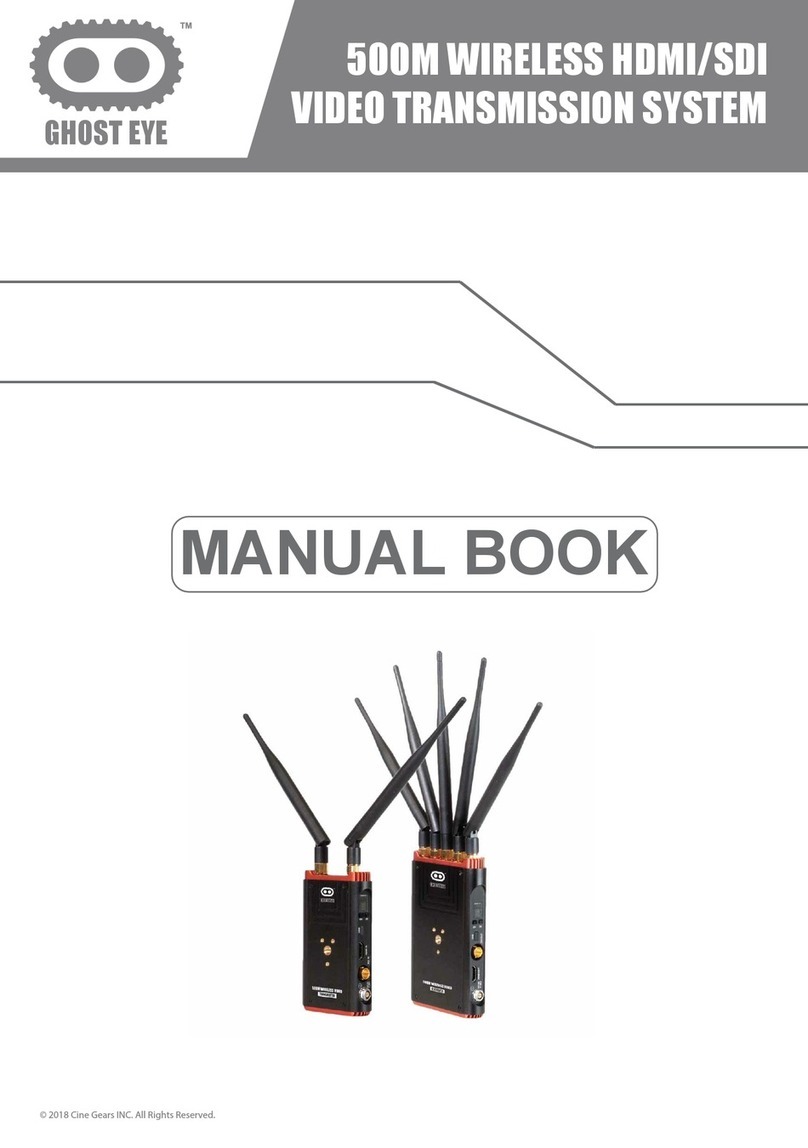
200M WIRELESS HDMI/SDI
VIDEO TRANSMISSION SYSTEM
MANUAL BOOK
GHOST EYE
© 2018 Cine Gears INC. All Rights Reserved.

Trademarks
Ghost-Eye Wireless Video Transmission SystemsTM are trademarks of Cine Gears
Inc. Web Interface.
Statement of Conditions
In the interest of improving internal design, operational function, and/or reliability, Cine
Gears Inc. reserves the right to make changes to the products described in this
document without notice.
Cine Gears Inc. does not assume any liability that may occur due to the use or applica-
tion of the product(s) or circuit layout(s) described herein.
FCC Compliance Notice: Radio Frequency Notice
The device has met the FCC 15.247 requirement. In order to comply with the FCC RF
exposure requirement, the user must keep 20cm away from the antenna.
This device has been tested and found to comply with the limits for a Class B digital
device, pursuant to part 15 of the FCC Rules. These limits are designed to provide
reasonable protection against harmful interference in a residential installation. This
device generates, uses, and can radiate radio frequency energy and, if not installed
and used in accordance with the instructions, may cause harmful interference to radio
communications. However, there is no guarantee that interference will not occur in a
particular installation. If this device does cause harmful interference to radio or televi-
sion reception, which can be determined by turning the equipment off and on, the user
is encouraged to try to correct the interference by one or more of the following mea-
sures:
• Reorient or relocate the receiving antenna.
Increase the separation between the equipment and receiver.
Connect the equipment into an outlet on a circuit different from that to which the
receiver is connected.
Consult the dealer or an experienced radio/TV technician for help.
•
•
•
Information to the user
The user’s manual or instruction manual for an intentional or unintentional radiator
shall caution the user that changes or modifications not expressly approved by the
party responsible for compliance could void the user’s authority to operate the equip-
ment. In cases where the manual is provided only in a form other than paper, such as
on a computer disk or over the Internet, the information required by this section may
be included in the manual in that alternative form, provided the user can reasonably be
expected to have the capability to access information in that form.
© 2018 Cine Gears INC. All Rights Reserved.

© 2018 Cine Gears INC. All Rights Reserved.
Contents
About the User Manual 1
1
1
2
3Interface Information
Specification
Features
Brief introduction
Quick Start Guide
LED Digits Display description 12
Application Recommendations 14
Disclaimers
17
19
21
7
About Cinegears
Trouble shooting

- Please read this manual carefully before you use this product and retain it properly
for future reference.
- If there is any question or difficulty about the operation of product, please feel free
to contact us or the dealer.
As the widely use of live broadcasting , many problems about wiring appear, such as
the high cost and short life time of the cable. Further, some other factors affect the
user experience of live broadcast, such as the insufficient cable protection and the
tread bycrowded people, which will lead to the poor cable transmission capability or
even to accident. 200M provides you more convenient and safer solution for live
broadcasting. With the advantage of long distance transmission, plug-and-play usage,
it can satisfy your various indoor and out door shooting requirements. With addition of
its free cable wiring needed,it will bring much safer and more professional experience
to you!
The product with its transmission distance of up to 200 meters can meet the demands
of film shooting, television broadcasting, live events, large conference, etc.
The product delivers uncompressed real-time 1080P/60Hz full HD video (4:2:2, 10bit).
Support HDMI, HD-SDI, 3G-SDI.
Full hardware design, plug & play;
5.1G-5.9G,support manual seting for channel switching and broadcast mode.
Support SDI time code transmission (time code format: ATC_VITC, ATC_LTC).
Support SDI camera recording trigger function (Start/Stop Flag) transmission.
Comply with EDID 1.1 ,support HDMI 1.3.
Support AES128 bit encryption.
- The company reserves the authority to modify the instruction manuals.
© 2018 Cine Gears INC. All Rights Reserved.
Introduction
About the User Manual
Brief Introduction
Features
1

Frequency
1080P 23.98/24/25/30/50/60 1080psf 23.98/24/25
1080i 50/59.94/60 720P 50/59.94/60
576P 576i 480p 480i
40MHz
PCM
ATC_VITC ATC_LTC
Up to 200m
Transmitter
Antenna External antenna * 2
17dBm
WorkingVoltage 7V~36V
<8W
Temperature
Receiver
WorkingVoltage 7V~36V
PowerConsumption <7W
Image transmission:5.1~5.9GHz
LED Digits Display
V-mount, 1/4" fixing screw hole
-10~50 C(Working);-40~80 C( Storage)
Item Specification
Bandwidth
Video Formats
Audio Formats
Time Code
Transmission distance
Transmission Power
HDMI input,SDI input, Mini-USB,Lemo(0B/2pin) DC in,
Antenna RPSMA, Power switch
Mechanical Interface
PowerConsumption
Antenna External antenna *5
Receiver Sensitivity -70dBm
HDMI output, SDI output, Mini-USB,Lemo(2pin) DC in,
Antenna RPSMA,Power switch
Mechanical Interface V-mount, 1/4" fixing screw hole
Temperature -10~50 C(Working);-40~80 C( Storage)
Interface
Size(mm)
Interface
Size(mm)
* As the product's continous improvment, the performance, design and specifications
are subject to minus change without prior notice.
117.5*72*27.5mm
144*95*27.5mm
LED Digits Display Display the working channel
Working channe number
© 2018 Cine Gears INC. All Rights Reserved.
Specification
Specification
2

V-MOUNT
Sony F-Type
Battery Plate
Power Switch
5.8G Antenna
Interface
Power indicator
Video indicator
OK Button
CH Button
Mini USB
HDMI IN
SDI IN
DC-IN
LED Digits DisplayL
5.8G Antenna
Interface
Transmitter Interface Interface
© 2018 Cine Gears INC. All Rights Reserved.
Interface Information
3

LED Digits Display
CH Button Switch the working channel
HDMI IN HDMI IN
SDI IN SDI IN
DC-IN
Power input interface (LEMO): support 7V to 36V
5.8G Antenna
Connector
Power Switch Power ON/OFF
V-MOUNT
Display the working channel 1~9, A(10), b(11)
Mini USB Be used for software upgrading
Sony F-Type
Battery Plate
Transmitter Interface Description
(Notice: please confirm the polarity before you
plugging in the power supply.)
Connect with RP-SMA antenna
Support installation of V-mount devices
Be used for installing external Sony F-type battery
OK Button Confirm the function selection
Item Specification
© 2018 Cine Gears INC. All Rights Reserved.
Interface Information
4

5.8G Antenna
Interface
Power indicator
Video indicator
Mini USB
LED Digits Display
OK Button
CH Button
SDI Out
HDMI Out
DC-IN
V-MOUNT
5.8G Antenna
Interface
Sony F-Type
Battery Plate
Power Switch
Receiver Interface
© 2018 Cine Gears INC. All Rights Reserved.
Interface Information
5

LED Digits Display
CH Button Switch the working channel
HDMI OUT HDMI OUT
SDI OUT SDI OUT
DC-IN
Power input interface (LEMO): support 7V to 36V
5.8G Antenna
Connector
Power Switch Power ON/OFF
V-MOUNT
Display the working channel 1~9, A(10), b(11)
Mini USB Be used for software upgrading
Sony F-Type
Battery Plate
Receiver Interface Description
(Notice: please confirm the polarity before you
plugging in the power supply.)
Connect with RP-SMA antenna
Support installation of V-mount devices
Be used for installing external Sony F-type battery
OK Button (Dual-
function button)
Confirm the function selection/Switching between
normal mode and enhanced anti-interference mode
Item Specification
© 2018 Cine Gears INC. All Rights Reserved.
Interface Information
6

1. Fix the antennas and adjust their angles as shown in the figure below.
(For details, please refer to the transmission distance description.)
HD M I S D ID C
DC IN
SDI IN
HDMI IN
7V-36V
Transmitter Installation Steps:
Notice: please rotate the golden
mental part of antenna to
fasten the antenna.
Antenna Pattern 1:
90° angle in the same plane
Antenna Pattern 2:
Right side 45° angle
rotation towards backside
2. Connect Tx with the camera via corresponding
power cable and HD video cables as shown in the figure below.
Li-battery 12V power adapter
Camera
© 2018 Cine Gears INC. All Rights Reserved.
Quick Start Guide
Product Installation
7

3. Turn on the power switch to start
power supplying.
Power Switch: ON turn on
OFF turn off
4.Press “CH” button to select the corresponding working channel of
receiver and then press “OK” button for confirmation.The LED digits
display will display one of the characters from 1 ~ 9, A and b when the video
signal of device is normal.(Tx and Rx use same default working channel)
5. The transmitter supports manually switching the SDI audio input mode by
long pressing “OK” button. (Notice: This function is only valid for SDI
audio input and won’t affect the HDMI audio input.)The default value of
SDI audio input mode is 0 and the decimal point will be set to be non-bright
under this mode; long press “OK” key button for more than 3 seconds,
and then the LED digits display will display SDI audio input mode as 1 while
the decimal point will be bright.
Audio input mode 0: adopt internal SDI clock signal of TX
Audio input mode 1: adopt SDI clock signal of SDI input signal
© 2018 Cine Gears INC. All Rights Reserved.
Installation
Quick Start Guide
8

D C
DC IN
7V-36V
HDMISDI
SDI monitor
SDI OUT
HDMI OUT
Receiver Installation Steps:
1. Fix the antennas and adjust their angles as shown in the figure below.
Notice:
please rotate the
golden mental
part of antenna to
fasten the antenna.
2. Connect RX with the monitor via corresponding power cable and HD
video cables as shown in the figure below.
12V power adapter
Li-battery
© 2018 Cine Gears INC. All Rights Reserved.
Quick Start Guide
9

3. Turn on the power switch to start
power supplying.
Power Switch: ON turn on
OFF turn off
4. Press “CH” button to select the corresponding working channel of
receiver and then press “OK” button for confirmation.The LED digits
display will display one of the characters from 1 ~ 9, A and b when the
video signal of device is normal; the monitor will display the image from
camera simultaneously.
© 2018 Cine Gears INC. All Rights Reserved.
Quick Start Guide
10

5. RX supports switching between normal mode and enhanced anti-
interference mode according to transmission distance and
interference level
a) Switch from normal mode to enhanced anti-interference mode: long press
“OK” for longer than 3 seconds to enter enhanced anti-interference mode,
and decimal point of digital tube (indicator) starts to flash slowly.
b) Switch from enhanced anti-interference mode to normal mode: long press
“OK” for longer than 3 seconds to enter normal mode, and decimal point
of the digital tube(indicator) goes out
c) Normal mode is default setting, supporting memory function,
so RX will enter last mode after reboot.
(Normal mode is recommended for long-distance transmission scenario;
enhanced anti-interference mode is recommended for short-distance
transmission and strong interference scenario)
© 2018 Cine Gears INC. All Rights Reserved.
Quick Start Guide
11

LED Digits Display
Transmitter
Power Indicator Video Indicator
TX : SDI Audio Input
Mode Indicator
n
LED Digits Display Status
LED Digits Display: Channel 1 ~ 9, A(10), b(11)
Video Indicator: Red: HDMI input; Yellow: SDI input
Power Indicator: Illuminate in working mode
SDI Audio Input Mode Indicator:
Decimal point light is off: SDI Audio Input Mode 0
Decimal point light is on: SDI Audio Input Mode 1
RX : Normal/Enhanced
Anti-interference
Mode Indicator
© 2018 Cine Gears INC. All Rights Reserved.
LED Digits Display description
12

25PSF in = 25 PSF out
29.97PSF=29.97PSF out
30PSF in = 30PSF out
23.98P in=23.98P out
24P in=24P out
25P in=25P out
29.97P in=29.97P out
30P in=30P out
50i in = 50i out
59.94i in = 59.94i out
60i in = 60i out
Support Full PSF resolution
Receiver
LED Digits Display: Channel 1 ~ 9, A, b
Power Indicator: Flash slowly when the network is not connected.
Light on normally when the network is connected.
Video Indicator: HDMI and SDI outputs are enabled together,
there are two status of the indicator
1:Red and Yellow light together: RX receives the signal from TX normally,
and HDMI and SDI outputs are working together
2:No light: No output signals via HDMI and SDI ports
Normal/Enhanced Anti-interference Mode Indicator :
Decimal point light is off : normal mode
Decimal point light flashes slowly: enhanced anti-interference mode
© 2018 Cine Gears INC. All Rights Reserved.
LED Digits Display description
Support Full PSF resolution
13

TX:7051RX:3051
Application Recommendations
1.Recommended Installation Method under Ideal Position
Make receiver to stand vertically; adjust antennas to a fan-shaped arrangement;
Make transmitter to stand vertically; adjust antennas to 90° angle in the same plane.
In order to reach the best performance of wireless transmission,
we recommend to meet the requirements as follows:
1. The vertical height of TX and RX should be same and more than 1.5m
2. TX and Rx are working under the condition of line of sight distance
3. Plane of TX antennas toward plane of RX antennas face-to-face
© 2018 Cine Gears INC. All Rights Reserved.
Application Recommendations
14

TX:7051RX:3051
2.Recommended Installation Method under Non-ideal Position
When the front side of the transmitter is not able to face to the receiver,
Please make receiver to stand vertically; adjust antennas to a fan-shaped arrangement;
Make transmitter to stand vertically; adjust the right side of the 2 transmitter
antennas towards backside by 45°.
Antenna Pattern 2:
Right side 45° angle
rotation towards backside
© 2018 Cine Gears INC. All Rights Reserved.
Application Recommendations
15

When the front side of the transmitter is not able
to face to the receiver, please try to adjust the
direction of transmitter antennas to make sure
that the formative fan-shaped arrangement
can face to the receiver for best signal transmission.
As shown in the right figure:
Because TX and RX are working on ISM band, wireless transmission
performance is relevant with level of interference intensity. If transmission
performance declines, we recommend to switch the wireless channel of
TX and RX simultaneously for improvement of transmission performance
3. Recommended Installation Method under Non-ideal Position
© 2018 Cine Gears INC. All Rights Reserved.
Application Recommendations
16

© 2018 Cine Gears INC. All Rights Reserved.
Trouble shooting
Trouble shooting
17
Table of contents
Other GhostEye Microphone System manuals