MASCOT RS-51B User manual

RS-51B / RS-55B
RS-31B / RS-33B
USER’S MANUAL
WIRELESS MICROPHONE SYSTEM
Channel

Contents:
Introduction
Quick Start Guide
Product Description
System Operation
Color Label Identification
Trouble Shooting
Specification
-------------------------------------------------------------------------- 1
------------------------------------------------------------------ 2
---------------------------------------------------------------- 4
------------------------------------------------------------------ 10
--------------------------------------------------------- 13
------------------------------------------------------------------- 14
------------------------------------------------------------------------- 15

This device complies with part 15 of the FCC rules. Operation is subject to the following
two conditions:(1)This device may not cause harmful interference and (2) This device must
accept any
The changes or modifications not expressly approved by the party responsible for
compliance could void the user’s authority to operate the equipment.
IMPORTANT NOTE: To comply with the FCC RF exposure compliance requirements, no
change to the antenna or the device is permitted.
could result in the device exceeding the
to operate the device.
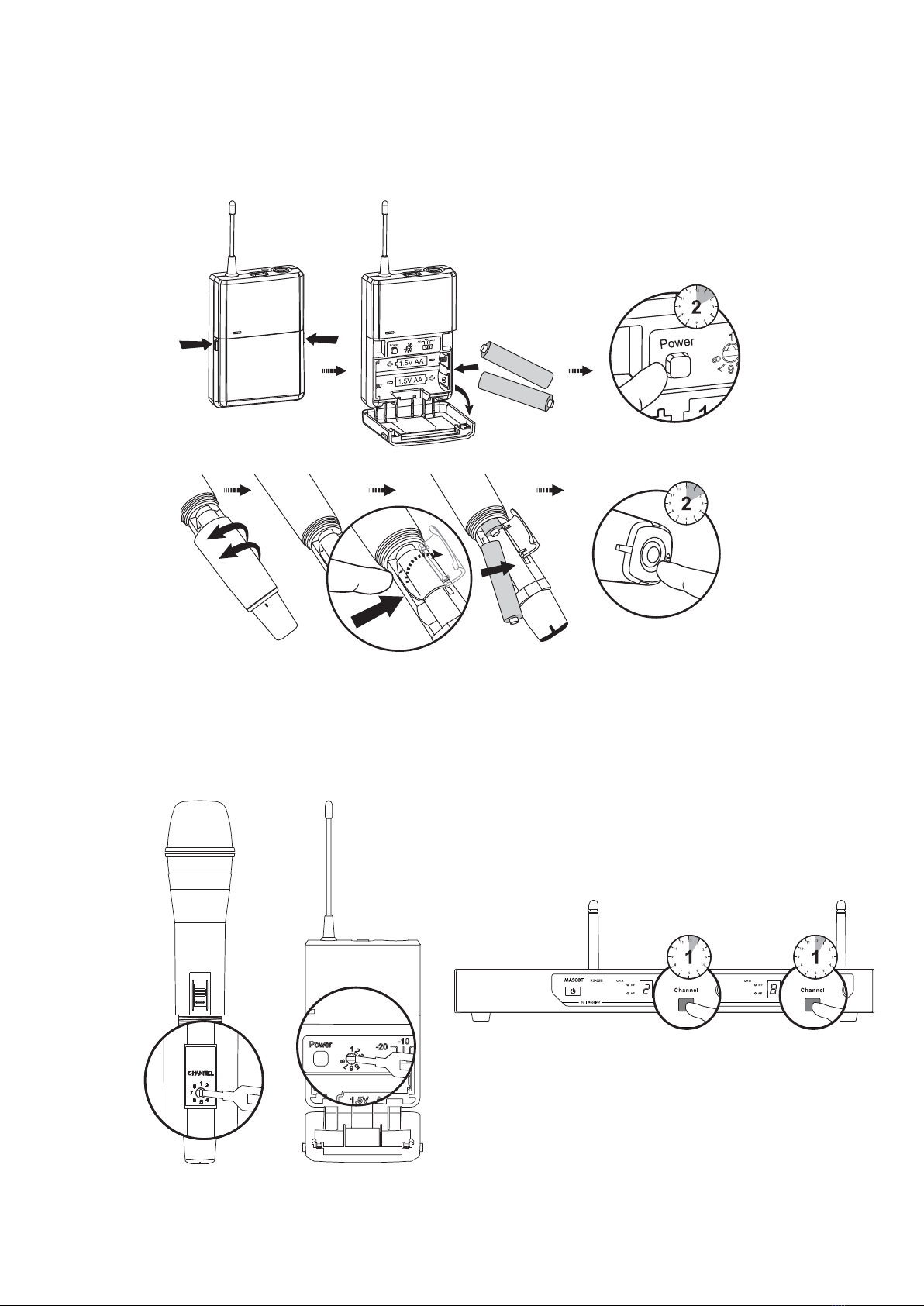
Thank you for purchasing our product. This PLL synthesized wireless microphone system
operates in UHF band frequency with 8 selectable channels. Please read this instruction
manual carefully before operating the system. This manual covers the function and operation
of the wireless microphone system.
Safety
Do not spill liquid on the appliance and do not drop it on a hard concrete floor.
Do not place the equipment near heat sources such as radiators, heating ducts, amplifier, etc.
Do not expose the equipment to direct sunlight, extremely dust, excessive moisture, rain,
mechanical vibrations, or shock.
Take out the battery from transmitter, if the appliance has been not used for a longer period.
This will avoid the damage resulting from a defective leaking battery.
WARNING: To reduce the risk of fire or electric shock, do not use the products near water
and do not expose them to rain or moisture.
Environment
When disposing the equipment, remove the batteries, separate the case, circuit boards,
and cables, and dispose of all components in accordance with local waste disposal rules.
Do not throw used batteries into a fire or garbage bin with domestic rubbish. Be sure to
dispose of used batteries in accordance with local waste disposal rules.
If the equipment is not going to be used for a long time, disconnect the AC adapter from
the power outlet. Please note that if you turn the equipment off while leaving the AC
adapter plugged in, it is not fully isolated from the power supply.
No guarantee claims for the equipment and no liability for any resulting personal damage
or material damage will be accepted if the equipment is used for other purpose than
originally intended, if the equipment is not correctly connected or operated, or if the
equipment is not repaired in an expert way.
Notice :
FCC Statement
interference received, including interference that may cause undesired operation.
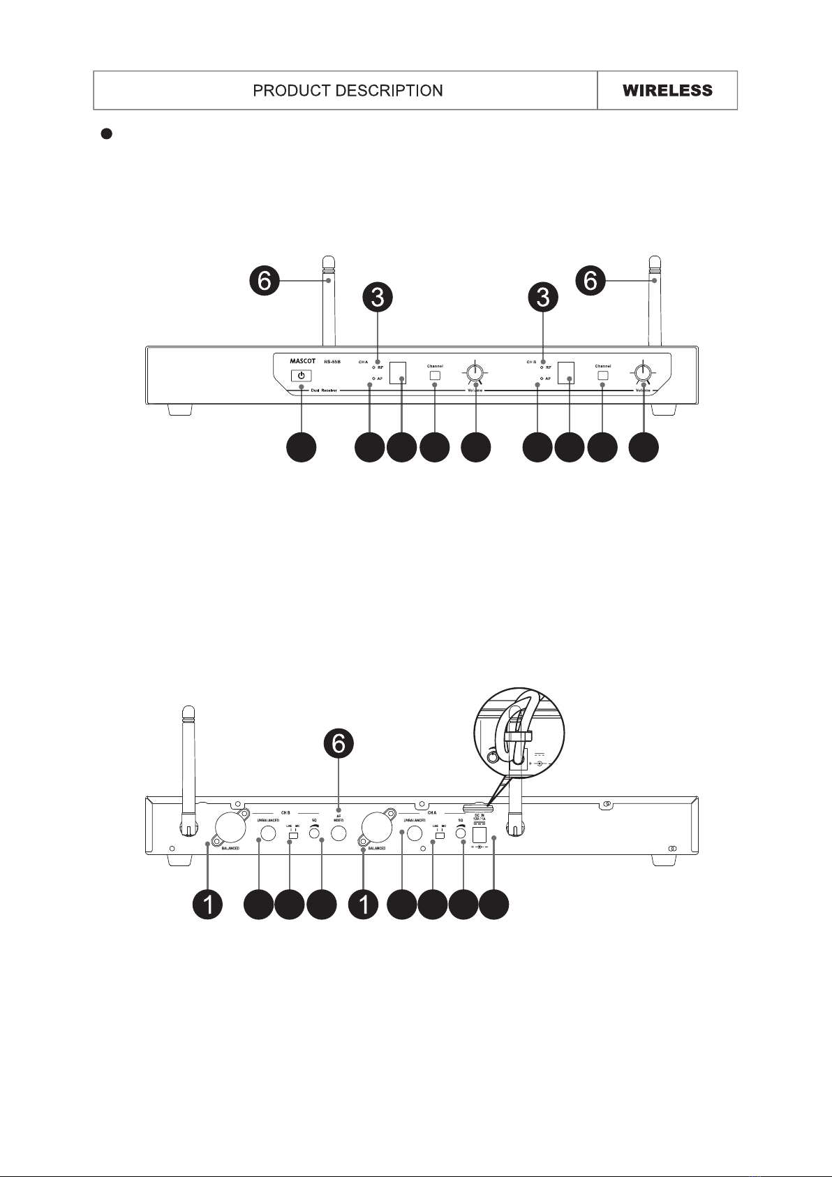
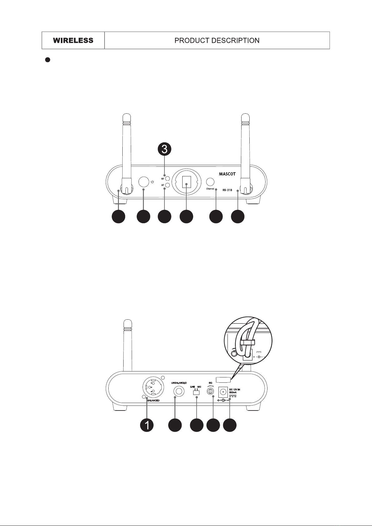
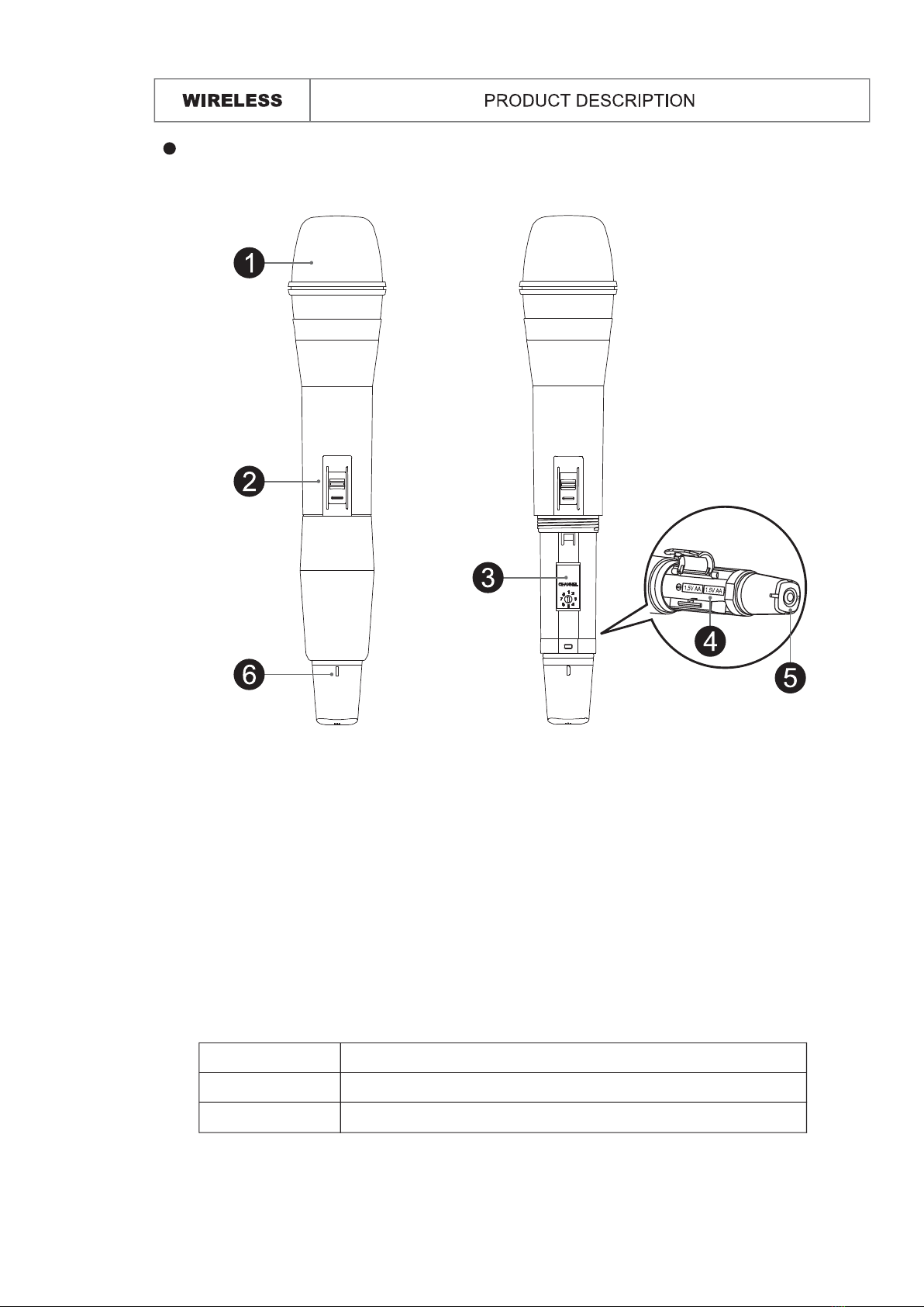
Introduction
Any change to the antenna or the device
RF exposure requirements and void user’s authority
1

1. Connected Receiver Power Cable
2. Connect Mixer or Amplifier
2
Quick Start Guide

3. Insert Batteries
4. Select channel
3
Quick Start Guide

Front :
Rear :
RS-51B: Diversity Receiver
4
Receiver
1. Balanced XLR Audio Output
2. Unbalanced 6.35mm Audio Output
3. MIC/LINE Switch: Use this switch to adjust audio output level for MIC level (-20dB) or
LINE level (0dB).
4. Squelch: Turn the knob to adjust the noise floor level.
5. DC Input Jack
1. Power Button: Press and hold for 2 sec. to turn the power on. Press and hold for 2
sec. to turn the power off.
2. AF Indicator: The indicator glows to indicate that audio signal has been received.
3. RF Indicator: The indicator glows to indicate that RF signal has been received.
4. LED Display: The 7 segment LED display shows the selected preset channel.
5. Channel Selector: Press and hold for 1 sec. to select the operating channels.
6. Antenna: Fixed UHF antenna.
7. Volume Control: Adjust the receiver output level.
DC 12V 500mA
MIC
SQ
1 2
3
4 5 66 7
1 32 4 5

5
Front :
Rear :
RS-55B: Diversity Receiver
Receiver
1. Balanced XLR Audio Output
2. Unbalanced 6.35mm Audio Output
3. MIC/LINE Switch: Use this switch to adjust audio output level for MIC level (-20dB) or
LINE level (0dB).
4. Squelch: Turn the knob to adjust the noise floor level.
5. DC Input Jack
6. Mix Out: The audio output for CH A and CH B is mixed.
1. Power Button: Press and hold for 2 sec. to turn the power on. Press and hold for 2
sec. to turn the power off.
2. AF Indicator: The indicator glows to indicate that audio signal has been received.
3. RF Indicator: The indicator glows to indicate that RF signal has been received.
4. LED Display: The 7 segment LED display shows the selected preset channel.
5. Channel Selector: Press and hold for 1 sec. to select the operating channels.
6. Antenna: Fixed UHF antenna.
7. Volume Control: Adjust the receiver output level.
DC 12V 500mA
MIC
SQ
1 2 4 5 7 2 4 5 7
3 32 24 4 5

Front :
Rear :
RS-31B: Diversity Receiver
6
Receiver
1. Balanced XLR Audio Output
2. Unbalanced 6.35mm Audio Output
3. MIC/LINE Switch: Use this switch to adjust audio output level for MIC level (-20dB) or
LINE level (0dB).
4. Squelch: Turn the knob to adjust the noise floor level.
5. DC Input Jack
1. Power Button: Press and hold for 2 sec. to turn the power on. Press and hold for 2
sec. to turn the power off.
2. AF Indicator: The indicator glows to indicate that audio signal has been received.
3. RF Indicator: The indicator glows to indicate that RF signal has been received.
4. LED Display: The 7 segment LED display shows the selected preset channel.
5. Channel Selector: Press and hold for 0.5 sec. to select the operating channels.
6. Antenna: Fixed UHF antenna.
DC 12V 500mA
MIC
SQ
32 4 5
1 2 4 5 66

Front :
Rear :
RS-33B: Diversity Receiver
Receiver
7
1. Balanced XLR Audio Output
2. Unbalanced 6.35mm Audio Output
3. MIC/LINE Switch: Use this switch to adjust audio output level for MIC level (-20dB) or
LINE level (0dB).
4. Squelch: Turn the knob to adjust the noise floor level.
5. DC Input Jack
6. Mix Out: The audio output for CH A and CH B is mixed.
1. Power Button: Press and hold for 2 sec. to turn the power on. Press and hold for 2
sec. to turn the power off.
2. AF Indicator: The indicator glows to indicate that audio signal has been received.
3. RF Indicator: The indicator glows to indicate that RF signal has been received.
4. LED Display: The 7 segment LED display shows the selected preset channel.
5. Channel Selector: Press and hold for 0.5 sec. to select the operating channels.
6. Antenna: Fixed UHF antenna.
DC 12V 500mA
MIC
SQ
Channel
3 32 24 6 4 5
1 2 24 5 5 66

8
UF-31B Handheld Microphone
1. Grille: Protects the microphone capsule and helps reduce breath sounds and wind
noise.
2. Talk Switch: Slide up the switch to talk and slide down to mute.
3. Channel Selector: 8 different selectable channels.
4. Battery Compartment: Insert two AA batteries here and make sure that the polarity of
batteries is correct.
5. Power Button: Press and hold for 2 sec. to turn the power on or off.
6. Power LED: Indicate the power / low battery level status.
LED Indicator Status
Green Ready
Flashing Red Low battery / power when less than 10 minutes operation

9
UT-51B Bodypack Transmitter
4
1. Power Button: Press and hold for 2 sec. to turn the power on or off.
2. Mute Button: With the transmitter on, a slight press for button will toggle between mute
and unmute function.
3. Power LED: Indicate the power / low battery level status.
4. Mute LED: Blue LED light on in mute status.
5. Channel Selector: Select the channel.
6. Battery Compartment: Insert two AA batteries here and make sure that the polarity of
batteries is correct.
7. Mini XLR Connector: Connect to the lapel microphone or headset microphone.
8. Gain Switch: The switch sets the audio input to -20dB, -10dB, 0dB
LED Indicator Status
Green Ready
Flashing Red Low battery / power when less than 10 minutes operation

LINEMIC
NBALANCED
Prior to setting up, please check that the transmitter and receiver are tuned to the same
frequency or channel. Two or more transmitters operating in the same frequency can not
be used at the same time and area.
VOLUME
MIC
SQ
DC
12V 50
min.
SQ
max.
SQ
Connected the provided DC power supply to
the receiver power input with an appropriate
AC power source. The LCD display will light
and the receiver is on.
Set the audio output level for
MIC: -20dB
LINE: 0dB (Default Setting)
Using the Volume Controller to adjust the AF
audio level to the input of the amplifier or mixer.
Never use the balanced and unbalanced audio
outputs at the same time! This may cause
signal loss or increased noise.
Use squelch to eliminate or suppress the
ambient RF noise.
Using a standard audio cable with 3-pin XLR
connectors or 6.3mm phone plugs to connect
the mixer or amplifier.
Default Setting: In minimum VOLUME position.
Defaulting Setting: In properly position.
10
Connecting the receiver

NOTE: When you don’t use this device for a long term period, please switch the power
switch to “off” mode to save more electric power.
Set up the handheld microphone / bodypack transmitter
Open the battery cover and insert batteries
into the battery compartment conforming
to the polarity (+)(-) marks.
Unscrew the handheld Mic and open the
battery cover to insert the battery into the
battery compartment and confirm the
marks of the polarity (+) (-).
Connect to the lavalier microphone,
headset microphone or guitar cable.
11

NOTE: When you don’t use this device for a long term period, please switch the power
switch to “off” mode to save more electric power.
Press for 2 seconds to turn the Handheld/
Bodypack transmitter on.
If the LED stays flashing , it indicates that
the battery will out of power soon and
should be changed.
Adjust the audio input level.
• 0dB
• -10dB (Default Setting)
• -20dB
Bodypack Handheld
• 0dB • -10dB • -20dB
Press Channel button on the receiver to
select for the clear channel.
Use the adjust pin to set the channel of
the transmitter.
Set up the handheld microphone / bodypack transmitter
12

Color Label Identification
You can also stick the color label on the receiver and transmitter for quickly identify
the pair system.
13

Trouble Shooting
whether is set too high or too low.
14

15
Receiver
Frequency Range
Case
: UHF520 ~ 937.5MHz (Regionally Selected)
: RS-51B : Half 19” EIA Rack Case
RS-55B : 19” EIA Rack Metal Case
RS-31B : Mini Case
RS-33B : Mini Case
Oscillator
Modulation
S/N Ratio
Image & Spurious Rejection
Receiving Sensitivity
AF Response
T.H.D.
IF Frequency
Dynamic Range
Tone Signal
Audio Output
Power Supply
Current Consumption
: PLL Synthesized
: FM
: 100dB, at 20KHz deviation and 60dBµV antenna input
: 70dB minimum
: At 5µV over 70dB S/N ratio
: 50Hz to 18KHz
: 1% (at 1KHz)
: 1st: 243.95MHz 2nd: 10.7MHz
: 100dB
: 32.768KHz
: Balanced & Unbalanced
: DC12V
: RS-51B : 150±10mA / RS-55B : 350±10mA
RS-31B : 120±10mA / RS-33B : 350±10mA
Dimension(MM) WxHxD : RS-33B : 262x42x102
RS-31B : 170x42x102
RS-55B : 400x42x183
RS-51B : 200x42x122
Weight : RS-51B : 365g / RS-55B : 1445g
RS-31B : 260g / RS-33B : 375g
*The specifications are subject to change without notice.
Handheld : Uni-Direction dynamic unit or
Bodypack : 0dB, -10dB, -20dB (3 settings)
: UHF520 ~ 937.5MHz (Regionally Selected)
Channel Select
Display
RF Power Output
Frequency Stability
Frequency Range
: Rotary switch
: 10mW (max.)
: 120±10mA
: ±0.005%
: 60dB below carrier frequency
: DC3V (1.5V x 2AA size batteries)
: LED shows the battery status
Current Consumption
Battery
Handheld/Bodypack Transmitter
Spurious Emission
Gain Setting
Mic Unit
Uni-Direction electret condenser unit
Bodypack: Lavalier Mic / Headset Mic
Dimension(mm) WxHxD : Handheld
Bodypack : 65x97x25
Weight Bodypack : 84g: Handheld : 240g
System Performance

Warranty card
Product Model Product Serial Numeber
Purchaser Phone
Address
Warranty Period:One year from purchase Date of purchase
Warranty& Service Terms:
Please read the instruction manual carefully before opeation.
The period of warranty shall start from the date of purchase of the product
and shall cover a period of one year.If our product has malfunctioned under
proper operation, we will repair it without any charge.
During the warranty period,we may charge you maintenance cost if the
following situations have happened:
1. Improper usage or self-disassembly of the machine and accessories which
cause product damage.
2. Any damage due to natural disaster or force majeure.
3. Consumable parts are excluded from warranty(e.g.microphone capsule,
grille,etc.)
Please well keep this warranty card.
It will not be re-issed if lost or damaged.
MASCOT ELECTRIC CO.,LTD
No.85, Changxing 1st St., Rende Dist.,Tainan City 717, Taiwan
Service Number 886-6-2710171


440-0051-1
This manual suits for next models
3
Table of contents
Other MASCOT Microphone System manuals