GIA 370-420 VHF Page/Party User manual

Pub. 42004-432E
GAI - TRONI CS
®
A HUBBELL C OMPANY
Model 370-400 UHF and 370-420 VHF
Page/Party®Radio Couplers
GAI-Tronics Corporation 3030 Kutztown Road Reading, PA 19605 USA
610-777-1374 800-492-1212 Fax: 610-796-5954
VISIT WWW.GAI-TRONICS.COM FOR PRODUCT LITERATURE AND MANUALS
Confidentiality Notice
This manual is provided solely as an installation, operation, and maintenance guide and contains sensitive
business and technical information that is confidential and proprietary to GAI-Tronics. GAI-Tronics
retains all intellectual property and other rights in or to the information contained herein, and such
information may only be used in connection with the operation of your GAI-Tronics product or system.
This manual may not be disclosed in any form, in whole or in part, directly or indirectly, to any third
party.
General Information
Product Overview
The Model 370-400 UHF and 370-420 VHF Page/Party® Radio
Couplers allow a GAI-Tronics Page/Party® system to
communicate with a wireless radio system. Radio users,
located outside the facility at a remote location or inside a
plant, can communicate with Page/Party® users.
The coupler works as a half-duplex system in that audio is only
heard in one direction at a time. The current audio path takes
precedent over the system and the other audio path cannot
engage until the current audio path releases control. The audio
path to the Page/Party® system is gated by the carrier detect
signal from the radio. A VOX circuit that monitors the audio
level on the page or party line, whichever is currently active,
gates the audio path to the radio.
The coupler converts audio levels from the Page/Party® system
to the appropriate radio signal levels that are then transmitted
on a defined carrier frequency programmed into the radio. The
Page/Party® Radio Coupler senses off-hook characteristics of
the Page/Party® system and routes party line audio or page line
audio to the radio. Party line audio takes precedence over page
line audio.
The coupler converts the radio signal to the appropriate signal levels for the Page/Party® system. The
module has a relay output that activates during the presence of the programmed carrier frequency.
Figure 1. Outline of Model 370-400

Pub. 42004-432E
Model 370-400 UHF and 370-420 VHF Page/Party® Radio Couplers Page 2 of 10
P:\Standard IOMs - Current Release\42004 Instr. Manuals\42004-432E.docx
05/18
Features
85–264 V ac or 24 V dc power operation
hybrid circuitry to eliminate unwanted sidetone
individual volume adjustment to and from the radio
off-hook detection on party line
16-level VOX detection circuitry for monitoring page or party line audio
33-ohm termination internal to unit
eight selectable programmed radio frequencies
selectable high or low radio output power
relay output activated by radio received carrier frequency
Radio Frequency Programming
The operating frequencies of the system must be programmed into the radio before the unit is installed in
the field. The radio programming software must be installed on a PC to program the coupler. The radio
programming kit is sold separately, P/N 19101-024.
Radio Programming Software installation
1. Place the CD in the computer CD-ROM drive.
2. Select the Start button; then select Run.
3. At the prompt, type x:\fscommand\setup.exe, where x represents the drive letter that is associated
with your CD-ROM drive.
A DTXL_PCPS icon should appear on the desktop display after successful installation.
Opening the Station
Remove the four screws from the front panel and remove the front panel from the rear enclosure.
Connecting the Programming Cable to the Radio
1. Unplug the Page/Party®Radio Coupler’s 15-pin D-connector from the radio.
2. Connect the DTXP-PAC cable assembly’s 15-pin D-connector into the radio.
3. Connect the RJ11-style plug of the 9/RTC-PAS cable into the mating receptacle on DTXP-PAC
cable.
4. Connect the DB-9 to DB-25 adapter to the other end of the 9/RTC-PAS cable.
5. Connect the DB-9 connector of the cable assembly to the computer serial port.
6. Connect the red and black leads of the 9/RTC-PAS cable to a 12 V dc power source (battery or power
supply), observing the polarity (red +, black −).

Pub. 42004-432E
Model 370-400 UHF and 370-420 VHF Page/Party® Radio Couplers Page 3 of 10
P:\Standard IOMs - Current Release\42004 Instr. Manuals\42004-432E.docx
05/18
Programming the Radio
1. Make sure the radio to be programmed is powered and connected to the PC (as described above)
before starting the programming software on the PC.
2. Start radio programming software on the PC.
3. Enter the receive (Rx) and transmit (Tx) frequencies for each channel. To enter the frequency, select
the channel, then the Edit button on the left.
4. Enter the Rx Frequency, Tx Frequency, and select a QC (Quiet Call) frequency or DQC (Digital
Quiet Call) code, if desired.
5. After entering the frequency and optional QC or DQC, program the radio by selecting Radio >
Program Radio from the tool bar.
6. After the radio is programmed (time bar disappears), disconnect the programming cable and
reconnect the radio to the 69574-001 PCBA.
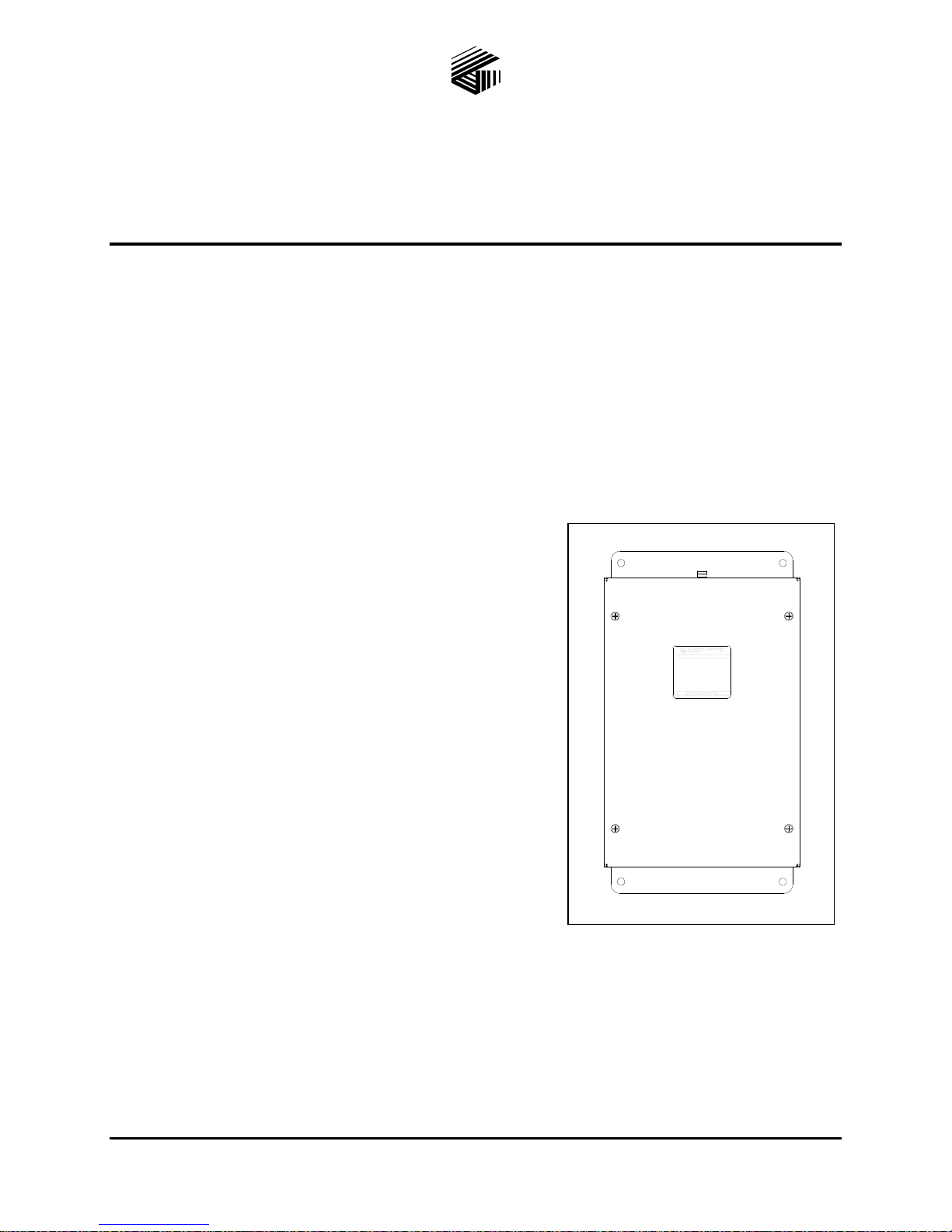
Attaching the Front Panel
After attaching the radio cable:
1. Place the front cover on the rear enclosure. Do not to pinch any cables.
2. Secure the front cover using the four screws and washers provided.
3. Torque the screws to 10–12 in∙lb (1.13–1.36 Nm).
Installation
Important Safety Instructions
Read, follow, and retain instructions—All safety and operating instructions should be read and
followed before operating the unit. Retain instructions for future reference.
Heed warnings—Adhere to all warnings of the unit and in the operating instructions.
Attachments—Attachments not recommended by the product manufacturer should not be used, as
they may cause hazards.
Servicing—Do not attempt to service this unit by yourself. Opening or removing covers may expose
you to dangerous voltage or other hazards. Refer all servicing to qualified service personnel.
This permanently connected apparatus must have a UL Listed 15-amp circuit breaker incorporated in
the electrical installation of the building.
USA and Canada Consult the National Electrical Code (NFPA 70), Canadian Standards Association
(CSA 22.1), and local codes for specific requirements regarding your installation. Class 2 circuit wiring
must be performed in accordance with NEC 725.55.
WARNING
—In 24 V dc systems: Under NO condition should this equipment be operated
from a battery charger without the batteries connected.
In 24 V dc systems, most chargers have an unloaded output of 35 to 45 volts that can quickly damage the
equipment designed for nominal 24 volts. The maximum battery voltage should never exceed the
maximum specified input voltage.

Pub. 42004-432E
Model 370-400 UHF and 370-420 VHF Page/Party® Radio Couplers Page 4 of 10
P:\Standard IOMs - Current Release\42004 Instr. Manuals\42004-432E.docx
05/18
Mounting the Enclosure
1. Mount the enclosure using the four 0.312-inch (8
mm) diameter holes located on the mounting
flanges with ¼-inch (M6) hardware. The
Page/Party® Radio Coupler is not supplied with
conduit or cable openings.
2. Remove the front panel and drill or punch entry
openings in the rear section of the enclosure (see
Figure 2 for suggested locations).
There must be a minimum of ½ inch (13 mm) of
material between entry holes. GAI-Tronics
recommends bottom entry only wherever
possible.
The standard mounting orientation (see Figure 2),
locates the power supply housing in the upper left
corner. The orientation of the enclosure can be
rotated 180º to allow clear access to the top. When
mounting the enclosure, use caution to avoid
damaging the internal components.
Antenna Installation
Select an appropriate antenna based upon the
frequency of the radio and connect it to the BNC
connector on the top of the enclosure (see Figure 3).
The antenna should be remotely mounted in a location
that provides line-of-sight communication to the
surrounding area. Refer to the Specifications section
for specific RF module frequency information.
Figure 2. Mounting Details and Wire Entry
Locations
Figure 3. Antenna Connection

Pub. 42004-432E
Model 370-400 UHF and 370-420 VHF Page/Party® Radio Couplers Page 5 of 10
P:\Standard IOMs - Current Release\42004 Instr. Manuals\42004-432E.docx
05/18
Field Wiring
Refer to Figure 4, No. 69574-001 PCBA, for reference to connection locations.
Figure 4. No. 69574-001 PCBA with attached Radio PCBA
Opening the Station
Remove the four screws from the front panel and remove the front panel from rear enclosure.

Pub. 42004-432E
Model 370-400 UHF and 370-420 VHF Page/Party® Radio Couplers Page 6 of 10
P:\Standard IOMs - Current Release\42004 Instr. Manuals\42004-432E.docx
05/18
Power
The Page/Party®Radio Coupler can be powered from the included universal ac power source or from a
24-volt dc power source.
ATTENTION
—Do NOT use both an ac and a dc power source at the same time.
AC Power
Field wire the universal ac power source to terminal block
TB1.
1. Attach #6 spade lugs to the power supply wires.
2. Connect the power supply wires to P1-LINE, P2-
NEUTRAL, and P3-EARTH.
NOTE:Terminal block TB2 is not used in this
configuration.
DC Power
Field wire the dc power supply to terminal block TB2.
1. Attach #6 spade lugs to the power supply wires.
2. Connect the dc power supply wires to the 24 VDC +
and 24 VDC –terminals.
NOTE:Terminal block TB1 is not used in this
configuration.
Audio and Control Signals
The Page/Party®Radio Coupler allows access to the audio lines along with relay outputs.
Table 3. P8—Page/Party®Interface
Pin Number
Pin Name
Function
1
PAGE L2
Bi-directional audio for 33-ohm page line
2
PAGE L1
Bi-directional audio for 33-ohm page line
3
PARTY L2
Bi-directional audio for 33-ohm party line
4
PARTY L1
Bi-directional audio for 33-ohm party line
Table 4. P7—Carrier Detect Output
Pin Number
Pin Name
Function
1
NC
Normally closed connection of carrier detect
2
COM
Common connection of carrier detection
3
NO
Normally open connection of carrier detection
Table 1. TB1—Universal AC
Power Supply Connections
Pin Number
Pin Name
1
INPUT LINE
2
INPUT NEUTRAL
3
EARTH
Table 2. TB2—24 Volt DC Connections
Pin Number
Pin Name
1
24 VDC +
2
24 VDC −
3
EARTH

Pub. 42004-432E
Model 370-400 UHF and 370-420 VHF Page/Party® Radio Couplers Page 7 of 10
P:\Standard IOMs - Current Release\42004 Instr. Manuals\42004-432E.docx
05/18
Settings and Adjustments
Jumper Settings
Radio Output Power, P5—The radio can be configured for either high or low power output. Default is
high power output (5 W).
Page Line Termination, P4—The page line can be terminated locally or remotely in the system. The
default is for remote termination (open). The party line is always terminated internally to the unit.
Terminating the party line remotely will cause the off-hook detection circuit to fail.
Selector Switches
VOX Threshold
Adjustment Switch, SW1:
Adjust the threshold of the
VOX using switch SW1 to
one of 16 levels to account
for the system signal to
noise level (see Table 5).
Radio Frequency Selector
Switch, SW2:
Configure the radio for one
of eight programmed
frequencies using the 16
position hex switch, SW2.
Each frequency is
selectable using either of
two positions on the switch
(see Table 6).
Level Adjustments
Radio to Page/Party®Volume Adjustment:
Adjust the volume from the radio to the Page/Party®lines
using potentiometer R21.
Page/Party®to Radio Volume Adjustment:
Adjust the volume from the Page/Party®lines to the radio
using potentiometer R42.
Attach the Front Panel
1. Place the front cover on the rear enclosure.
2. Secure the front cover using the four screws and washers provided.
3. Torque the screws to 10–12 in∙lb (1.13–1.36 Nm).
Table 6. SW2—Radio
Frequency Selector Settings
Radio
Channel
Selector
Switch
Position
1
0 or 8
2
1 or 9
3
2 or A
4
3 or B
5
4 or C
6
5 or D
7
6 or E
8
7 or F
Table 5. SW1—Nominal VOX
Threshold Settings
Selector
Switch
Position
VOX
Threshold
(mV)
0
380
1
350
2
330
3
300
4
275
5
250
6
225
7
200
8
190
9
160
A
140
B
110
C
90
D
60
E
40
F
20

Pub. 42004-432E
Model 370-400 UHF and 370-420 VHF Page/Party® Radio Couplers Page 8 of 10
P:\Standard IOMs - Current Release\42004 Instr. Manuals\42004-432E.docx
05/18
Operation
The Page/Party®station operator controls the coupler’s connection to the page or party line by the off-
hook and page conditions.
When all stations are on-hook, the Page/Party®Radio Coupler is connected to the page line.
When any station is off-hook on the designated party line, the Page/Party®Radio Coupler is
connected to that party line.
When the Page/Party®station operator lifts the handset and presses the handset pressbar, the
Page/Party®Radio Coupler is connected to the page line.
Calling a Radio Operator from the Page/Party® System
For paging and subsequent party line conversation:
1. Lift the handset and select the dedicated party line using the five-position rotary selector switch.
2. Press the handset pressbar to connect to the page line in the radio coupler and page the desired
individual.
The page is heard over the Page/Party®system and the radio frequency. After the page:
3. Release the pressbar to connect the station to the party line in the radio coupler and wait for a
response.
The radio operator then responds by keying the radio and talking.
The resulting communication is half duplex, meaning the person currently talking has control of the
conversation. The other operator must wait until the first person has finished talking. After the
conversation is complete, the Page/Party®operator should place the handset back on-hook.
Calling a Page/Party®
Operator from a Radio
For paging and subsequent party line conversation:
1. Turn on the radio and activate the push-to-talk (PTT) button.
2. Page the desired individual. The Page/Party®station operator lifts the handset, selects the dedicated
party line using the five-position rotary selector switch and responds to the radio operator.
The resulting communication is half duplex, meaning the person currently talking has control of the
conversation. The other operator must wait until the first person has finished talking. After the
conversation is complete, the Page/Party®operator should place the handset back on-hook.
Specifications
AC/DC Input
AC Power Supply
Input voltage ............................................................................................120/230 V ac (nominal), 50/60 Hz
Current draw @ nominal 120 V ac....................................................................................................270 mA
Current draw @ nominal 230 V ac....................................................................................................150 mA
DC Power Supply
Input voltage .......................................................................................................................................24 V dc
Current draw @ nominal 24 V dc............................................................................................................. 1 A

Pub. 42004-432E
Model 370-400 UHF and 370-420 VHF Page/Party® Radio Couplers Page 9 of 10
P:\Standard IOMs - Current Release\42004 Instr. Manuals\42004-432E.docx
05/18
Audio
33-ohm output with +/−1.5 kHz deviation, narrowband.........................................1.5 V RMS, factory aligned
2.8 V RMS maximum
Distortion.............................................................................................................................. <1.5% @ 1 kHz
Radio output deviation with 1.5 V RMS from 33-ohm line................+/−1.5 kHz narrowband, factory aligned
VOX threshold.................................................(see Table 5), Nominal VOX Threshold Settings, on Page 7
VOX activation time........................................................................................................................... <50 ms
VOX hold time......................................................................................................................................... >1 s
Off-Hook Monitoring
Activation time.................................................................................................................................... <50 ms
Deactivation time................................................................................................................................ <50 ms
Relay Outputs
Maximum load........................................................................................................................2 A @ 30 V dc
0.5 A @ 125 V ac
Mechanical
Construction/finish.................................................... 16-gauge cold-rolled steel; safety orange powder coat
Mounting...............................................................wall or column, four 0.31-inch (7.8 mm) mounting holes
Dimensions .............................................................12.0 H × 8.0 W × 5.0 D in (304.8 × 203.2 × 127.0 mm)
Shipping weight................................................................................................................... 10.5 lb (4.76 kg)
Net weight.............................................................................................................................. 9.5 lb (4.31 kg)
Environmental
Operating temperature range...............................................................................................−20 ºC to +60 ºC)
Relative humidity......................................................................................... non-condensing 85% maximum
RF Module
General
Frequency range.............................................................................................................VHF: 154–174 MHz
UHF: 450–470 MHz
Antenna impedance.................................................................................................................................50 Ω
Encoder/decoder ....................................................................................................CTCSS tone, DCS digital
Receiver (measurement procedures made per ANSI/TIA/EIA-603)
Sensitivity (12 dB SINAD)................................................................................................................0.25 μV
Inter-modulation ........................................................................................VHF @ −67 dB; UHF @ −67 dB
Transmitter (measurement procedures made per ANSI/TIA/EIA-603)
RF output ..................................................................................................................................... 2 W or 5 W
Spurious and harmonic emissions................................................................................< −20 dBm maximum

Pub. 42004-432E
Model 370-400 UHF and 370-420 VHF Page/Party® Radio Couplers Page 10 of 10
P:\Standard IOMs - Current Release\42004 Instr. Manuals\42004-432E.docx
05/18
Approvals
FCC Identifier.............................................................................................................. VHF: AIERT 17–145
UHF: AIERT 17–445
FCC Compliance..................................................................................................................................Part 90
IC Certification ........................................................................................................VHF: 1084A-RIT 17145
UHF: 1084A-RIT 17445
Frequency Restrictions
Certain transmit and receive frequencies within the coupler’s range are unavailable. Refer to the tables
below for these frequencies. Do not attempt to program the coupler to these frequencies.
Table 7. VHF (138–174 MHz) Restricted Frequencies
Receive
(MHz)
Transmit
(MHz)
Receive
(MHz)
Transmit
(MHz)
Receive
(MHz)
Transmit
(MHz)
Receive
(MHz)
143.9900
143.9900
158.3900
158.3900
172.7900
172.7900
143.5425
143.9925
143.9925
158.3925
158.3925
172.7925
172.7925
143.5575
143.9950
143.9950
158.3950
158.3950
172.7950
172.7950
157.9425
143.9975
143.9975
158.3975
158.3975
172.7975
172.7975
157.9575
144.0000
144.0000
158.4000
158.4000
172.8000
172.8000
172.3425
144.0025
144.0025
158.4025
158.4025
172.8025
172.8025
172.3575
144.0050
144.0050
158.4050
158.4050
172.8050
172.8050
144.0075
144.0075
158.4075
158.4075
172.8075
172.8075
144.0100
144.0100
158.4100
158.4100
172.8100
172.8100
Table 8. UHF (450–470 MHz) Restricted Frequencies
Receive
(MHz)
Transmit
(MHz)
460.80000
460.78750
461.23750
460.79375
461.24375
460.80625
461.25625
460.81250
461.26250

(Rev. 10/06)
Warranty
Equipment. GAI-Tronics warrants for a period of one (1) year from the date of shipment, that any
GAI-Tronics equipment supplied hereunder shall be free of defects in material and workmanship, shall
comply with the then-current product specifications and product literature, and if applicable, shall be fit
for the purpose specified in the agreed-upon quotation or proposal document. If (a) Seller’s goods prove
to be defective in workmanship and/or material under normal and proper usage, or unfit for the purpose
specified and agreed upon, and (b) Buyer’s claim is made within the warranty period set forth above,
Buyer may return such goods to GAI-Tronics’ nearest depot repair facility, freight prepaid, at which time
they will be repaired or replaced, at Seller’s option, without charge to Buyer. Repair or replacement shall
be Buyer’s sole and exclusive remedy. The warranty period on any repaired or replacement equipment
shall be the greater of the ninety (90) day repair warranty or one (1) year from the date the original
equipment was shipped. In no event shall GAI-Tronics warranty obligations with respect to equipment
exceed 100% of the total cost of the equipment supplied hereunder. Buyer may also be entitled to the
manufacturer’s warranty on any third-party goods supplied by GAI-Tronics hereunder. The applicability
of any such third-party warranty will be determined by GAI-Tronics.
Services. Any services GAI-Tronics provides hereunder, whether directly or through subcontractors,
shall be performed in accordance with the standard of care with which such services are normally
provided in the industry. If the services fail to meet the applicable industry standard, GAI-Tronics will
re-perform such services at no cost to buyer to correct said deficiency to Company's satisfaction provided
any and all issues are identified prior to the demobilization of the Contractor’s personnel from the work
site. Re-performance of services shall be Buyer’s sole and exclusive remedy, and in no event shall GAI-
Tronics warranty obligations with respect to services exceed 100% of the total cost of the services
provided hereunder.
Warranty Periods. Every claim by Buyer alleging a defect in the goods and/or services provided
hereunder shall be deemed waived unless such claim is made in writing within the applicable warranty
periods as set forth above. Provided, however, that if the defect complained of is latent and not
discoverable within the above warranty periods, every claim arising on account of such latent defect shall
be deemed waived unless it is made in writing within a reasonable time after such latent defect is or
should have been discovered by Buyer.
Limitations / Exclusions. The warranties herein shall not apply to, and GAI-Tronics shall not be
responsible for, any damage to the goods or failure of the services supplied hereunder, to the extent
caused by Buyer’s neglect, failure to follow operational and maintenance procedures provided with the
equipment, or the use of technicians not specifically authorized by GAI-Tronics to maintain or service the
equipment. THE WARRANTIES AND REMEDIES CONTAINED HEREIN ARE IN LIEU OF AND
EXCLUDE ALL OTHER WARRANTIES AND REMEDIES, WHETHER EXPRESS OR IMPLIED BY
OPERATION OF LAW OR OTHERWISE, INCLUDING ANY WARRANTIES OF
MERCHANTABILITY OR FITNESS FOR A PARTICULAR PURPOSE.
Return Policy
If the equipment requires service, contact your Regional Service Center for a return authorization number
(RA#). Equipment should be shipped prepaid to GAI-Tronics with a return authorization number and a
purchase order number. If the equipment is under warranty, repairs or a replacement will be made in
accordance with the warranty policy set forth above. Please include a written explanation of all defects to
assist our technicians in their troubleshooting efforts.
Call 800-492-1212 (inside the USA) or 610-777-1374 (outside the USA) for help identifying the
Regional Service Center closest to you.
This manual suits for next models
1
Table of contents