4
0704EN February 2020
Metering systeMs
Heat Interface UnIt wItH electronIc regUlatIon
ge556Y401, ge556Y402
ge556-2 serIes
047U53918
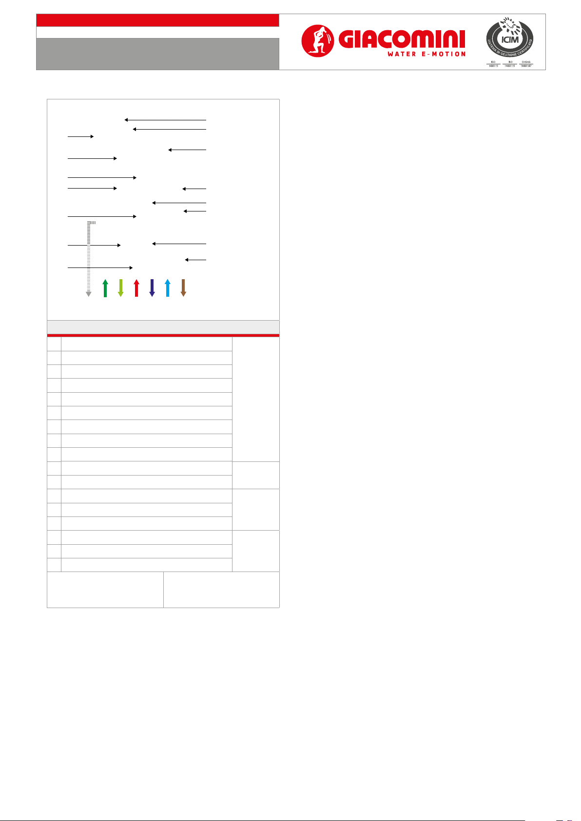
Settings of the remote control/chronothermostat
Operation in mode: OFF, SUMMER, WINTER, HEATING ONLY
The selection of the operating mode is done by repeatedly pressing the
button .
O: “OFF”and the current time are shown on the display. Only the antifreeze
function (if set) is enabled in this mode. Any request for the DHW or heating
mode operation is ignored.
Summer: the measured room temperature, the current time and the icon are
displayed . The DHW, if set, and the antifreeze function are enabled in this
mode. Any request for the heating mode operation is ignored.
Winter: the display shows the measured room temperature, the time and the
current day, the icons and the program set for the current day. All DHW,
heating and, if set, antifreeze functions are enabled in this mode.
Heating only: the display shows the measured room temperature, the time
and the current day, the icon and the program set for the current day. All
heating and, if set, antifreeze functions are enabled in this mode. Any request
for the DHW mode operation is ignored.
Clock and temperature setting
Depending on the operating mode selected (OFF / SUMMER / WINTER
/ HEATING ONLY) by pressing the button , the clock and the
temperature of the boiler can be set.
The value is displayed for a time equal to the display settings time delay and
is identied by its ashing icon. Press key to pass to the next value
and turn the knob to modify the value.
Clock: press key until the icon and the time value start to ash .
Turn the knob to select the desired time.
Press the knob to pass to the minutes.
The minutes start ashing: turn the knob to select the desired
minutes. Press the knob to pass to the day of the week. The days of
the week start ashing: turn the knob to select the desired day. Press
the knob to conrm the value entered.
Day Set point: press key until the icon and the day set point
value start to ash .
Turn the knob to select the desired value.
Night Set point: press key until the icon and the night set
point value start to ash .
Turn the knob to select the desired value.
Heating Set point: press key until the icon and the heating set
point value start to ash .
Turn the knob to select the desired value.
DHW Set point: press key until the icon and the DHW set
point value start to ash .
Turn the knob to select the desired value.
Kd: this setting is only available if the remote control is congured as
the modulator with the use of the external probe (P04 = 2 or 3). press key
until the icon and the relative value start to ash. Turn the knob
to select the desired value.
NB:
For the other operating modes of the remote control, refer to the
corresponding instruction sheet.
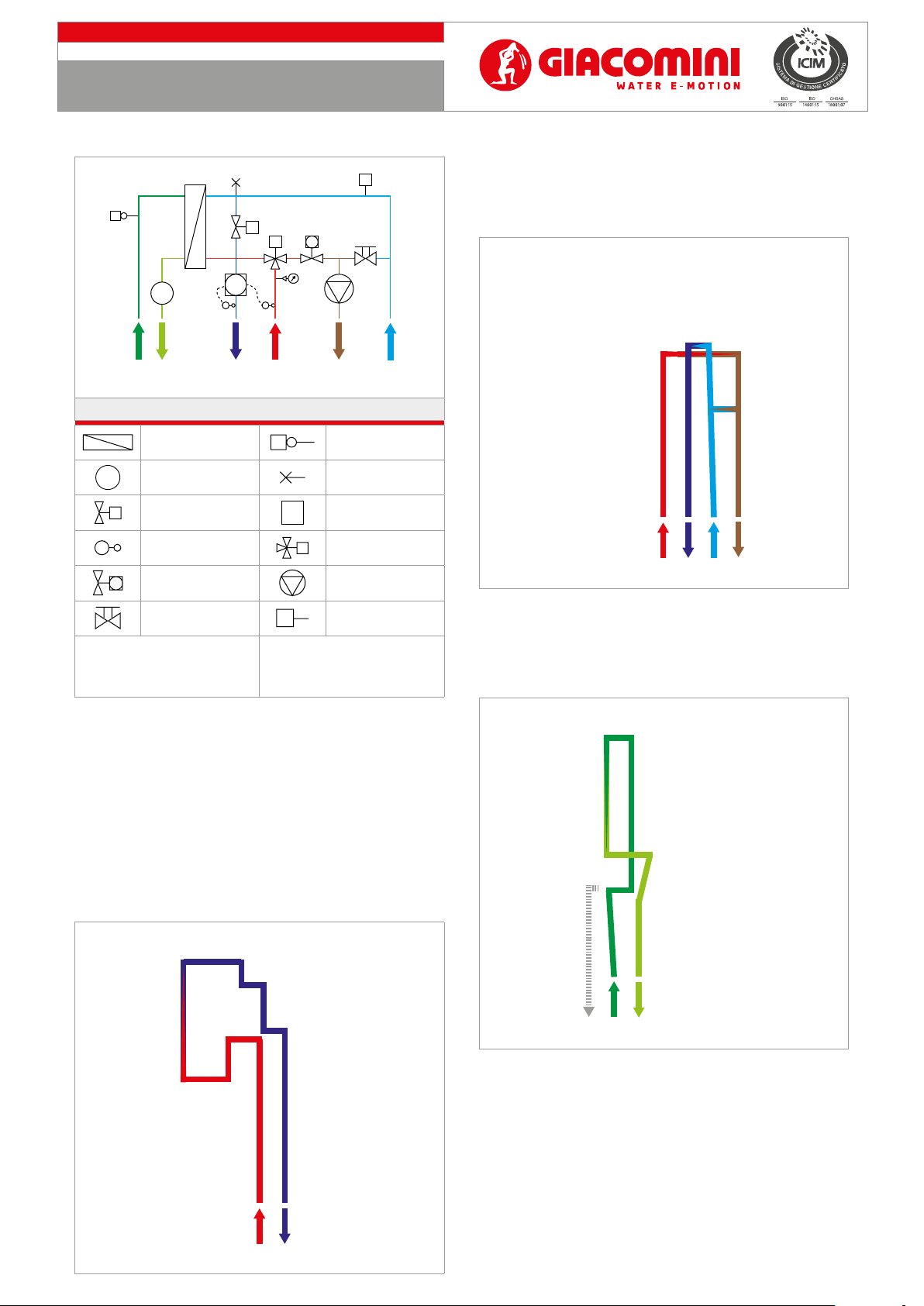
Electric connections
Electronic board
An electrical cabinet IP55 containing the electronic control board is located
at the top right of the HIU.
• The HIU is powered electrically by connecting the 230 V mains supply to the
three-pin terminal board M1 of the electronic board.
•The remote control /chronothermostat (K480Y002) is connected to terminals
23-24 of the electronic board.
• The external temperature probe (K365PY002) is connected to terminals 27-
28 of the electronic board.
• The optional safety thermostat (K373/K373I), is connected to terminals 39-40
of the electronic board.
• Multizone additional control to terminals 21-22 on the electronic board
(additional thermostats to be ordered separately).
24 23 22 21 20 1932 31 30 29 28 27 26 2540 39 38 37 36 35 34 3342 41
1 2 3 4 5 6 7 8 9 10 11 12 13 14 15
L N
M1
18
17
16
SAFETY
THERMOSTAT
K373 / K373I
REMOTE COMMAND /
CHRONOTHERMOSTAT
K480Y002
CONTROL FOR
MULTIZONE
EXTERNAL
TEMPERATURE
PROBE K365P
230 VAC
Technical data
• Electronic board power supply of the HIU: 230 V
• Supply voltage frequency: 50÷60 Hz
• Ambient operating temperature: -20÷60 °C
• Ambient storage temperature: -20÷80 °C
• Humidity: max 90 % @ 40° C non-condensing
• Maximum absorption: 7 VA
• Maximum length of external probe cable: 30 m
• Maximum length of remote control cable: 30 m
M-Bus
To connect the M-Bus data transfer cable to the concentrator, refer to the data
sheet of the heat energy meter used.
Protection and safety systems
Warning. Risk of burns and electric shock. The HIU must only
be accessed by skilled personnel, authorised by the building
administrator.
It is important that the HIU are accessed only by skilled personnel authorised
by the building administrator: the box is locked. As optional is possible to
install a K373/K373I safaty thermostat to prevent the high temperature on
the heating side.
Checks and Maintenance
Warning. Installation must be carried out by skilled personnel, authorised
by the building administrator. Respect the regulations regarding the use
(installation, xing, etc.), operation, recalibration and replacement of the
meters. Refer also to the assembly instructions provided with the meter.
Warning. Before connecting the template to the HIU, remove the lock
nuts from the threaded connections.
Heating circuit pressure
Regularly check the pressure in the heating circuit by means of the
manometer: the pressure value must be kept above 1 bar (values lower than
this may cause cavitation, damaging the circulator). There is a pressure switch
with a 0,8 bar setting to protect the circulator.
Warning. The HIU will turn o and the display on the remote control
signals an error E71 if the pressure is less than 0,8 bar.
Fill the system again to restart the HIU.
You must set up a lling system for heating - i.e. a connection from the
domestic circuit to the heating circuit, with a suitable backow preventer.
Attention: risk of burns. Use the manual air vent to remove the air in the circuit.