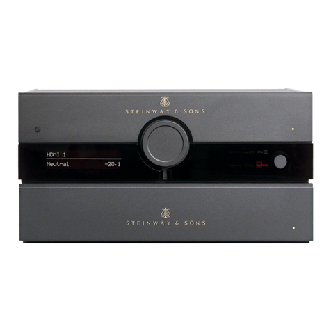
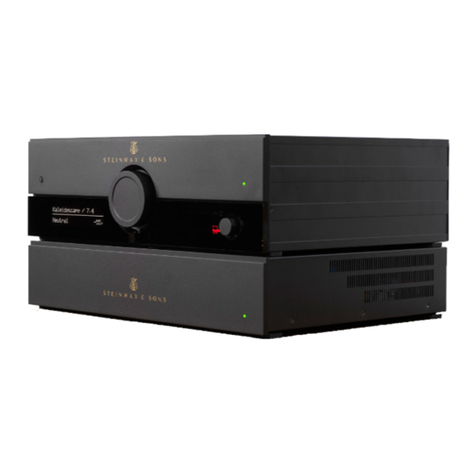
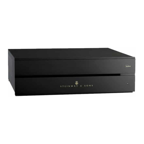
STEINWAY LYNGDORF P1 User manual

MODEL P1 SURROUND SOUND PROCESSOR
INSTALLATION MANUAL
VERSION 1.9
[Skriv tekst]

TABLE OF CONTENTS
TABLE OF CONTENTS......................................................................................2
INTRODUCTION.................................................................................................3
COMPLIANCE ....................................................................................................3
PRE-INSTALLATION..........................................................................................4
OPERATING VOLTAGE.....................................................................................7
VENTILATION REQUIREMENTS.......................................................................7
CABLE CONNECTIONS.....................................................................................7
HOME AUTOMATION SYSTEM INTEGRATION................................................8
IP CONTROL ......................................................................................................8
INSTALLATION...................................................................................................9
TROUBLESHOOTING......................................................................................36
NETWORK SETUP...........................................................................................38
POWER SUPPLY SPECIFICATIONS...............................................................42
TRADEMARKS.................................................................................................43
SERVICE INFORMATION ................................................................................44
2

INTRODUCTION
This Installation Manual was created to assist you with setting up and using your Steinway Lyngdorf
electronics and accessories.
Please read all material carefully prior to installation or first use of your Steinway Lyngdorf product. If
you need additional assistance, contact your Steinway Lyngdorf representative or email
service@steinwaylyngdorf.com.
COMPLIANCE
WEEE
The European Parliament and the Council of the European Union have issued the Waste
Electrical and Electronic Equipment Directive. The purpose of the Directive is to prevent
waste of electrical and electronic equipment and to promote reuse, recycling, and other
forms of waste recovery. Steinway Lyngdorf products and the accessories packed with them are
subject to the WEEE Directive. Please dispose of any waste materials in accordance with your local
recycling regulations. Products and equipment which must be collected for reuse, recycling, and other
forms of recovery are marked with the icon of the crossed-out waste receptacle.
FCC
Steinway Lyngdorf products and accessories comply with parts 15 and 68 of the FCC rules. Operation
is subject to the following two conditions: (1) this device may not cause harmful interference; and (2)
this device must accept any interference received, including any interference that may cause
undesired operation. Model A1/A2 amplifier and Model P1 processor contain TX FCC ID:
TYOJN5139M0
Changes or modifications not expressly approved by the party responsible for compliance could void
the user’s authority to operate the equipment. Equipment marketed to a consumer must be capable of
complying with the necessary regulations in the configuration in which the equipment is marketed.
3

PRE-INSTALLATION
Unpacking the product
Carefully remove the unit and accessory kit from the carton and check for shipping damage. Contact
both the shipper and your Steinway Lyngdorf representative immediately if the unit bears any sign of
damage. All Steinway Lyngdorf equipment is carefully inspected before leaving our factory. Note:
Keep the shipping carton and all packing material for future use or in the unlikely event that the unit
needs servicing. If this unit is shipped without the original packing, damage could occur and void the
warranty.
Inventory
Check the list below to ensure that all necessary product components have been delivered. Report all
discrepancies to your Steinway Lyngdorf representative immediately.
•Installation manual
•Power cord
•Link cable
•Installer remote
•RoomPerfect microphone
•Microphone cable
•Microphone stand
The Installer’s Kit
The Installer’s Kit contains the following items:
•Laptop
•Wireless router
•Installer remote
•RoomPerfect microphone
•Microphone cable
•Microphone stand
4

Rear Socket Panel
1. Component video input
2. Composite and S-video input
3. HDMI input and output (5 input and 1 output)
4. RS232 connector for home automation control
5. Network connection
6. USB service connection (SW updates/loading speaker setups)
7. Component video output (BNC: main / RCA: zone 2)
8. Composite output
9. S-video output
10. Compact flash card slot
11. Trigger and IR input/output
12. Multichannel analogue audio input
13. Microphone input for RoomPerfect™ calibration
14. Coaxial digital audio input
15. Connector for RF extender
16. Lyngdorf Digital Link output A, B and C
17. Mains input and on/off switch
18. Balanced analogue audio input
19. Stereo analogue audio input
20. AES/EBU digital audio input
21. Optical digital audio input
22. Zone 2 analogue audio output
5

LED signaling - P1
Red: Standby
Green: On
Blinking green: Switching on
Orange: Zone 2 active
Blinking red: Power failure
Blinking red/green: Update of software.
When update is complete, the P1 will automatically switch off and on again.
6

OPERATING VOLTAGE
Steinway Lyngdorf products must be connected to the mains power system only.
Note: it is of utmost importance that the mains voltage switch is set appropriately. Turning the
product on with the incorrect voltage setting will cause serious damage to the product. Use only mains
power cables and power plugs approved by Steinway Lyngdorf or you may cause damage to the
electronics and infringe the warranty.
VENTILATION REQUIREMENTS
Steinway Lyngdorf products do not have built-in ventilation, nor do they need any special cooling
systems for heat dissipation.
When installing this product in an open cabinet or elsewhere without rack mounts, keep a minimum
clearance of one inch on all sides. Do not install it in an environment that will expose it to excessive
heat.
CABLE CONNECTIONS
Cables and Plugs
Use only the power cables included with the product when connecting it to the mains. Use only mains
cables and power plugs approved by Steinway Lyngdorf. Using other cable and/or plug types will void
the warranty and may cause damage to the system.
Connecting
For cabling between the processor and amplifiers, please use RJ45 to RJ45 B standard cables.
•For cable lengths less than 1 meter, use CAT5E/shielded CAT6 cable.
•For cable lengths in excess of 1 meter, use double-shielded CAT5E cables.
•All RJ45 connectors should be shielded.
Please refer to the wiring diagram supplied by Steinway Lyngdorf to determine which cables you
need. Poor quality cables may violate safety/ EMC regulations as well as cause significant noise and
interference. Use only cables and connectors approved by Steinway Lyngdorf.
7

HOME AUTOMATION SYSTEM INTEGRATION
The Model P1 is compatible with home automation systems via the RS232 and network connector on
the rear socket panel. The P1’s IR and trigger connections can also be programmed for use in a
home automated system.
IP CONTROL
Open a TCP connection on port 50042 and use the same protocol as on the serial interface (see
Model P1 Serial Control Manual). Use Telnet, Putty, or similar programs to open the TCP connection.
If you do not know the IP-address of the P1 on your local network, the P1 also supports Bonjour
Discovery service to locate the P1 on the local network. Before connecting the Model P1 to the
network, please download and install Apple Inc.´s “Bonjour Print Services” software on the computer
you want to set up the Model P1 with. This software will make it easy to access the Model P1 on the
network. For Windows operating systems the software can be found at
http://www.apple.com/support/bonjour/.The software is built-in as part of the Apple Inc.´s Mac
operating system (not iOS devices).
8

INSTALLATION
Using in a Rack System
The Model P1 processor is equipped from the factory with feet for free-standing placement on a shelf
or table. However, the Model P1 can also be mounted in a rack, along with the amplifiers and other
connected sources. Before mounting the Model P1 in a rack, you must first remove the feet and
attach the brackets included with the Model P1 as shown in the illustration.
Turn the Model P1 upside down and place it on a stable, even surface. Using a TORX 10 screwdriver,
remove the screws and washers holding the feet in place (see illustration). Keep the feet, screws and
washers for future use. The screws used to fasten the rack brackets to the Model P1 are in the holes
designated for the brackets when the product leaves the factory. Remove these four screws from the
Model P1 using the same screwdriver you used to detach the feet from the Model P1. Fasten the
brackets for rack mounting to the Model P1 as shown. You can now mount the Model P1 in the rack
using the screws included with the rack system you have chosen.
9

Reminder:
•The Model P1 should always have at least one inch of free space on all sides;
•Should be placed in an environment free of excessive heat;
•When placed in a rack system, Model P1 should be placed at the bottom of the rack, with the
amplifiers above it. This allows for proper dissipation of the heat generated by the amplifiers
without adverse effects on the Model P1.
10

The Installer Remote
The Model P1 comes with a dedicated remote control for use in installations and updates involving a
connected screen.
… Move up and down in menus;
Browse available settings in a menu
… Move left and right in menus
OK … Select a menu to view;
Store a selected setting;
Activate the main user menu
… Turn sound volume up
… Turn sound volume down
MENU … Access the Installer menu
… Switch the Model P1 on or off
… Mute and restore the sound
BACK … Return to the previous menu
INFO … Shows operational status
11

Use the Installer Remote to Name Sources
In the Source Setup menu you can name sources you have connected to the Model P1. This is done
using the arrow buttons on the Installer Remote. When you have selected the Edit option in the
menu, press the up or down arrow buttons to highlight the source you wish to rename, then press OK.
You can then do the following:
•Press the left arrow or the BACK button to delete a character.
•Press the up or down buttons repeatedly to browse through characters. Digits, lower-case
letters, upper-case letters, and punctuation characters (including space) are available.
•Press the right arrow button to select the highlighted character and move to the next
character.
•When the source name is complete, you can store the name selecting the carriage return
symbol (
↵
) from the character list and pressing OK.
Changing the Batteries
The installer remote is shipped with two AAA batteries. If the
Model P1 does not respond to remote control commands, it
may be because the remote control batteries need to be
replaced. Use a cross-tip (PH1) screwdriver to remove the
locking screw from the battery compartment.
The locking screw is at the base of the remote control, just
below the CE-label. When you have removed the locking
screw, the battery compartment is automatically ejected from
the bottom of the remote control. Remove the used batteries
and replace them with two AAA-size alkaline batteries. Insert
the battery compartment and tighten the locking screw.
12

Set-Up
Note: To perform the installation using the Installer Remote, you will need a connected display to
show the on-screen menu (OSD). If a screen is not available, or if you prefer to perform the web-
based installation, use the laptop PC and the wireless router in the Installer’s Kit to set up the Model
P1. Both setup procedures are explained in this manual.
Set up your Steinway Lyngdorf Model P1 Surround Sound Processor by following these steps in this
order:
1. ID-assign all Model A1/A2 amplifiers via dip-switches on A1/A2 socket panel according to the
wiring diagram for the installation.
2. Check that the mains voltage switch on the A1/A2amplifiers are correctly set to either 115V or
230V. The Model P1 will automatically detect the voltage and does not have a mains voltage
switch.
3. Connect speakers to the Model A1/A2 amplifiers.
4. Connect Model A1/A2 amplifiers to Model P1 and to each other as shown in the project-
specific wiring diagram included with every Steinway Lyngdorf system.
5. Connect external audio and video sources to the Model P1.
6. Connect power to the Model P1, the amplifiers, and all connected audio and video sources.
7. Switch on the Model P1 with the installer remote.
8. Access Installer menu via Web or via the Installer Remote.
9. Load Speaker Configuration file, page 19.
10. Verify Setup, page 20.
11. Check speaker phases, refer to speaker installation manuals
12. Run RoomPerfect™ Guided Set-up.
See RoomPerfect™ Installation Manual for more information.
13. Set up sources, page 21.
14. Optional: Add remote control in the P1 Remote Control Setup, page 33.
15. Save and back-up settings.
These steps complete the basic Model P1 set-up. For further programming options (zone set-up etc.)
refer to the Table of Contents.
13

Installation via Installer Remote: Connect a Screen
You can connect a screen to the Model P1 using any of the video output sockets on the back of the
Model P1, such as HDMI or component. However, the zone video outputs are off by default and
cannot be used for system setup purposes. For further information about the rear panel, refer to
Model P1 Rear Panel on page 5. NOTE: If an HDMI display is connected to the Model P1, it will not
be possible to view picture content via the analogue outputs. Disconnect the HDMI display and repeat
the setup.
Installation via Web: Connect to the Model P1
The optional Installer’s Kit includes a laptop PC, a wireless router and a CAT5 Ethernet cable. Using
this cable, connect the network socket on the back of the Model P1 to one of the ports on the wireless
router labeled 1-4. The laptop connects automatically to the wireless router when switched on. If you
wish to perform the installation via Web, but are not using the Installer’s Kit, you must either connect
the Model P1 to an existing network or use a crossover network cable for direct connection. For
further information about network setup, refer to Network Setup on page 30.
14

Final Connections
1. Connect all external equipment, such as a Blu-ray player or home automation system, to the
Model P1, including inputs, outputs and mains.
2. Connect all speakers to the amplifiers and connect the amplifiers to the Model P1 processor
as shown in the wiring diagram for the installation.
3. Connect the amplifiers and the Model P1 processor to the mains and flip the switch on the
back of each product to turn it on.
Installation via Installer Remote – Access the Installer Menu
Once the necessary connections have been completed, you can access the menu system by pressing
the MENU button on the Installer remote control.
Installation via Installer Remote – Menu Navigation
Press the up and down arrow buttons on the Installer remote to move between sub-menus or
between the options in a menu. Press the right arrow button to highlight the current setting for a
specific option. While a setting is highlighted, press the up and down buttons to browse through the
available settings. Press OK to store a setting. Press BACK to return to the previous menu.
15

Installation via Web – Access the Installer Menu
Switch on the PC and router supplied in the Installer’s Kit. Access the Model P1 Installer menu via the
shortcut on the desktop, or enter the IP-address of the P1 in the address field of the Internet browser
(http://192.168.1.222/setup.html). To enter the main user menu website, enter only the IP-address.
NOTE: If there is more than one Model P1 in the setup, the new Model P1 must be assigned to the
existing network. For more information, refer to Network Setup on page 30.
16

Installation via Web – Menu Navigation
Click Setup to access the Installer menu.
Click a menu name at the top of the window to open a sub-menu of the Installer menu, such as
Speaker & Room. Click an option tab at the left of the window to view the current settings for that
option. Click the arrow next to a setting to view alternative settings. Click a white input field directly to
be able to enter a new setting, name or value. Click Save to save your settings or Back to return to a
previous menu without saving.
Menu Hierarchy – Installer Menu
•Speaker And Room Setup
oSpeaker Configuration
oRoom Perfect
Guided Setup
Advanced Options
oLevel Offsets
oDistance Settings
Unit
Position
•Source Setup
oEdit
oCreate New
oDelete
oArrange
•Audio Processing Setup
oAudio Mode Setup
oDolby Setup
oDTS Setup
oAdvanced Audio Setup
oVoicing Setup
•Zone Setup
oPower
oFixed Volume
oVideo Output
oEdit Zone Sources
•System Setup
oVideo Setup
oSerial Setup
oNetwork Setup
oTrigger Input Setup
oTrigger Output Setup
oP1 Remote Control Setup
Add Remote
17

Remove Remote
Assign Remote
Set Channel
•General Setup
oOSD Feedback
o2d OSD Position
•Device Management
oBackup And Restore
New Backup
Restore Backup
Delete Backup
oRead Roomperfect Data
oSoftware Info
oSoftware Update
oFactory Defaults
18

Speaker Configuration
The Speaker Configuration menu provides information about the current speaker channel
configuration, allowing you to select a configuration that is either stored on the Model P1, on a laptop,
or on a connected memory stick. Upload the desired configuration to the Model P1 and verify the
setup.
Press the down button on the Installer remote to highlight Select Setup and press OK. If using the
Web installation tool, click Change Speaker Configuration. Press the right button to be able to
select the location of the setup to be loaded and press the up or down buttons to browse the available
locations. Press OK to confirm your selection.
In the Web interface, click Select Configuration Location to browse locations and click the relevant
location in the list. Press the down button to highlight Select Setup and press OK. Press the up or
down button to select a configuration from the list and press OK to confirm your selection. In the Web
interface, click the down arrow next to Select Speaker Configuration to view the available
configurations and click Use this setup to select a configuration.
19

To verify the setup, press the down button to highlight Verify Setup and press OK. When verifying
the setup, pink noise is emitted from each speaker in turn. If the speaker playing the pink noise is the
same as the speaker highlighted in the menu, press OK on the installer remote or click OK in
the menu.
Note that there are some differences between the options available via the Installer remote and the
Web interface. The Web interface allows you to verify individual speakers in the setup, while the
verification includes all speakers when performed via the OSD interface. In addition, the Web
interface allows you to select a setup stored on the Model P1, on the Installer laptop or on a memory
stick connected to the laptop, while the OSD interface allows for setup uploads only from the Model
P1 or from a memory stick connected to the Model P1.
20
Other manuals for P1
2
Table of contents
Other STEINWAY LYNGDORF Recording Equipment manuals

STEINWAY LYNGDORF
STEINWAY LYNGDORF Steinway & Sons P300 User manual

STEINWAY LYNGDORF
STEINWAY LYNGDORF D User manual

STEINWAY LYNGDORF
STEINWAY LYNGDORF P200 Use and maintenance manual

STEINWAY LYNGDORF
STEINWAY LYNGDORF P1 User manual

STEINWAY LYNGDORF
STEINWAY LYNGDORF P300 2.1 User manual

STEINWAY LYNGDORF
STEINWAY LYNGDORF P200 User manual