Electronaut M97 User manual

M97 COMPRESSOR/LIMITER
USER’s GUIDE
Serial Number Built By Build Date Ship Date Line Voltage set to
120 240
ELECTRONAUT COMPANY
Revision 0, January 2016

USER’S GUIDE 2
ELECTRONAUT COMPANY M97 COMPRESSOR/LIMITER
SERIOUSLY.
Read this entire manual before plugging in and turning on the M97!
Refer servicing to qualified personnel only!
To prevent electric shock, do not operate the M97 near water or moisture!

USER’S GUIDE 3
ELECTRONAUT COMPANY M97 COMPRESSOR/LIMITER
TABLE OF
CONTENTS
CONTACT
INFORMATION 5
DECLARATION of CONFORMITY 5
THANK YOU SINCERELY 6
GETTING STARTED 8
INSPECTION 8
OPENING THE CRATE 8
REMOVING THE M97 FROM
THE CRATE 8
THOROUGH INSPECTION
PROCEDURE 9
CONFIGURATION 9
FRONT PANEL 9
REAR PANEL 9
B+ ADJUST (325V) KNOB 10
BALANCE/CHASSIS KNOB 10
IEC POWER INLET SWITCH 10
INSTALLATION 11
AIRFLOW AND THERMAL
CONSIDERATIONS 11
CALIBRATION 11
POWER UP the M97 11
CALIBRATING THE B+ VOLTAGE 11
CALIBRATING THE BALANCE 12
THE BALANCING SYSTEM 12
BALANCE CALIBRATION
PROCEDURE 12
BALANCE/CHASSIS 14
AT THIS POINT THE M97
SHOULD BE PROPERLY CALIBRATED
AND READY FOR SERVICE
REFERENCE 15
INPUT ATTENUATOR 15
THE INPUT ATTENUATOR and the
HIGH FREQUENCY RESPONSE 17
THE CONTROLLING AMPLIFIER 18
DC THRESHOLD 18
ATTACK 18
RELEASE 19
ATTACK and RELEASE
INTERDEPENDENCE 19
THE USABILITY OF THE FASTEST
ATTACK TIMES 19

USER’S GUIDE 4
ELECTRONAUT COMPANY M97 COMPRESSOR/LIMITER
SUGGESTED SET-UP FOR
TRANSIENT LIMITING: 19
UNDERSTANDING THE EFFECTS
OF THE AC AND DC THRESHOLD
CONTROLS 20
COMPRESSION CURVES 21
A NOTE ABOUT WORKFLOW 22
CHOOSING A CURVE BY
MAXIMUM OUTPUT 22
THE METERING SYSTEM 25
METER MODE KNOB 25
THE SIGNAL GENERATOR 26
MAKING GOOD USE OF THE
TONE AND METER 26
SET FOR UNITY GAIN: 26
FIGURE OUT WHERE THE “KNEE”
(OR EFFECTIVE THRESHOLD) OF
THE COMPRESSION CURVE IS: 26
HIGH PASS FILTER 27
BYPASS/COMPRESS/PASS 27
BYPASS 27
COMPRESS 27
PASS 27
The FUNCTION SWITCH 28
NORMAL 28
SIDECHAIN 28
INTERLOCK 28
SIDECHAIN/INTERLOCK 28
EXTERNAL 28
LINKING TWO M97S FOR STEREO 29
BLOCK DIAGRAM OF SIGNAL AND
CONTROL CIRCUITRY 30
POWER SCHEME 31
METER MODE SWITCH 31
IEC POWER INLET 31
IEC POWER CABLE 31
REPLACING THE FUSES 32
MAIN FUSES 32
INTERNAL FUSES 32
REPLACEMENT FUSE PART
NUMBERS 33
TUBE COMPLEMENT 33
OPTIONAL REMOTE-CUTOFF
TUBES 35
TUBE SOCKET WIRING AND TUBE
COMPATIBILITY 36
HEATER VOLTAGE TOGGLE
SWITCH 36
REPLACING THE TUBES 36
WARRANTY & REGISTRATION 37
SERVICING 37
SPECIFICATIONS 38
ACKNOWLEDGEMENTS 39
REIN NARMA 39
DR. DANIEL FLICKINGER 39
MIKE AND KAY DORROUGH 39
EARLY BELIEVERS 39
TABLE OF FIGURES 40
TABLE OF TABLES 41

USER’S GUIDE 5
ELECTRONAUT COMPANY M97 COMPRESSOR/LIMITER
CONTACT
INFORMATION
Electronaut Company
333 N Oakley Blvd STE 100
Chicago, IL 60612 U.S.A.
(312) 212-3983 (skype)
All information provided in this manual is
thought to be accurate and free of errors at
the time of printing; however, Electronaut
Company shall not be held liable for any errors
or omissions in this manual, nor any
subsequent damage resulting from the use of
the information in this manual. This manual
and any future updates can be downloaded
from the Electronaut Company website, at:
www.electronaut.info/manuals
This user’s manual contains information
protected by copyright. No part of this manual
may be reproduced in any form without prior
written consent from Electronaut Company.
©2002–2016 Electronaut Company
M97_UsersManual.pdf
DECLARATION of
CONFORMITY
Name of Manufacturer:
Electronaut Company
Address of Maufacturer:
333 N. Oakley Blvd. Ste 100
Chicago, IL 60612
USA
Product:
M97 Compressor/Limiter
Declaration:
ELECTRONAUT COMPANY is committed to
manufacturing products that are
fully-compliant with the RoHS Directive.
The M97 Compressor/Limiter complies with
the requirements of the Low Voltage Directive
(73/23/EEC) and the protection requirements
of the EMC Directive (89/336/EEC) issued by
the Commission of the European Community.
The M97 Compressor/Limiter is built
with RoHS-compliant components and is
assembled with RoHS-compliant lead-free
solder and assembly processes.

USER’S GUIDE 6
ELECTRONAUT COMPANY M97 COMPRESSOR/LIMITER
First of all,
THANK YOU
SINCERELY
for adding the M97 Compressor/Limiter to
your system. This compressor is the result of
literally thousands of hours of eort studying,
experimenting, designing, building, testing,
listening, redesigning, rebuilding, retesting,
relistening, (insert seemingly ininite loop
here), until a compressor finally emerged
that seemed refined enough to be worthy
of production. The sheer amount of work
required to undertake such a project begs the
question: does the world really need another
monster tube variable-mu1compressor?
Aren’t there already enough Fairchild clones
available?
The answers are unequivocally YES, and YES.
The year 2016 marks 110 years since the triode
vacuum tube was invented in Chicago in 1906.
As we look back over this incredible span of
ingenuity, a trend-line immediately reveals a
constant incremental progress, with creative
thinkers picking up where others left oand
pushing things a little bit further, inspired by
limitations they thought could be improved
upon. Every single audio equipment designer
throughout history benefited from the work
done by their predecessors, and the trend
of incremental progress happened because
people were driven to look forward and think
of new ideas. The engineers that created the
tools we musicians and recordists depend
upon generally shared three key things: a
willingness to study and learn from the past,
a solid understanding of the present, and a
creative vision for the future.
Something interesting started to happen
within the last couple of decades: musicians
and engineers began to realize that despite
a century of constant progress, many old
designs still held their own against new
designs, and in a lot of instances the older
designs simply sounded better. One hundred
years of constant improvement had also been
heavily influenced by 100 years of economic
interests, and the result wasn’t always good
for the sound. This realization, combined with
the emergence of internet auction services
and a globally interconnected world, inspired a
frenzy of trading in vintage electronics, which
in turn inspired a frenzy of manufacturers
issuing ‘clones’ of vintage designs.
Deeply rooted in Electronaut’s philosophy is
a belief that audio equipment design should
be informed not only by an engineering
perspective, but also from a musician’s
perspective. If we consider equipment design
from a musician’s perspective, some things
immediately become clear: cloning other
people’s designs from the past is basically
the same thing as being in a cover band.
Cloning is an attempt to celebrate the work
of people who left behind a legacy that still
may have untapped market potential, just as
a classic-rock cover band may find paid work
playing other people’s songs at weddings
or corporate events. There’s nothing wrong
with that, and there are many examples of
designers who have labored tirelessly to
reproduce every detail of a vintage design to
exacting standards, flaws and all, just as there
are musicians who have labored tirelessly to
perfect every riin the Beatles’ discography.
A lot of people really want to hear songs from
the past performed live, so naturally someone
will step up and provide such an experience.
That’s just how the world works.
But the world works in other ways too: people
are creative and not everyone is interested in
mimicking other people’s original ideas. Many
people have their own ideas and a strong
desire to actualize them, and that’s the reason
we have new music and art and books and
movies.
For some people, admiration for the great
work of the past reaches a fever pitch,
resulting in a belief that these past works are
so perfect that they can never be improved
upon. Again, viewed from the musician’s
perspective, this seems totally absurd: try
convincing musicians that they shouldn’t
bother to write new music because great
music has already been achieved!
The world needs another variable-mu
compressor because the variable-mu
technique is an amazing idea with a totally
unique sound that has stood the test of time,
and continues to show new potential even in
a vastly dierent technological world. Simply
USER’S GUIDE 7
ELECTRONAUT COMPANY M97 COMPRESSOR/LIMITER
stated, the idea still works amazingly well, yet
there is still plenty of room for improvement.
But does the M97 sound like a Fairchild or not?
The M97 is a heavy-duty, single-stage variable-
mu compression amplifier with a fast and
powerful controlling amplifier, and as such it
shares many of the qualities that made the
Fairchilds sound the way they do. However,
no attempt has been made to mimic the
Fairchild’s limitations. Instead, Electronaut
designed a series of improvements that
just make sense in a 21st century vari-mu,
including: continuously-variable attack and
release controls instead of a small number
of fixed time constants, a higher-current
controlling amplifier providing faster attack
and improved peak transient reduction
capability, a significantly-improved balance
calibration method for reduced distortion and
thump-free operation, Lundahl transformers
for improved frequency response and optimal
interfacing, a 24-position balanced bridged-T
input attenuator, a tube regulated high voltage
power supply filtered solely by a large choke
and four polypropylene capacitors, and a
vastly superior dB-accurate metering system
displaying input and output level, threshold
level, gain reduction, 2nd harmonic distortion,
and even peak transient reduction!
Ultimately, the important characteristic is the
audio circuit topology: the Fairchild was a
single-stage variable-mu compressor with a
powerful controlling amplifier, and at the time
it was arguably the best implementation of
that particular technique. What made it such a
great sounding compressor was not that it had
a magic combination of flaws; what made it
great was that it expanded the usability of the
variable-mu concept to the extent that it could
handle nearly any type of program material —
something previous variable-mu compressors,
arguably, could not achieve.
One of the main advantages of the single-
stage approach is an incredibly simple signal
path: an input transformer, a tube amplifier,
and an output transformer. Not even a single
capacitor is present in the signal path.
Not all variable-mu compressors are built
this way — many currently available designs
economize on the vari-mu stage and add
additional capacitively-coupled gain stages
to make up for it, but this is a move in the
direction of a more complex signal path, which
in Electronaut’s belief, is fine when necessary
but less than ideal.
Simpler is almost always better, and the
single-stage variable-mu concept managed to
maintain a simple signal path while oering
ample control of the audio’s dynamics.
Electronaut chose to use this approach as its
jumping opoint, and to try and hunt down
things that could be improved upon, not only
in terms of sonics, but in usability, interface,
and features.
In Electronaut’s view, the prevailing spirit of
pro audio equipment design is the desire to
constantly improve, just as a musician may
practice for a lifetime to constantly improve.
An environment where recordists exhibit
a healthy resistance to stagnation and the
status quo is better for every musician who
ever wants to make a record. We can let
the luddites be luddites without criticism or
judgement, and remember that they don’t
have to stand in the way of new ideas.
With this spirit in mind, Electronaut humbly
presents the M97 Compressor/Limiter. I
couldn’t be happier with the results, and I
can’t wait for you to hear it!
Rob Roy M. Campbell
January, 2016

USER’S GUIDE 8
ELECTRONAUT COMPANY M97 COMPRESSOR/LIMITER
GETTING STARTED
Preparing the M97 for service requires the
following five steps to be carried out in order:
1) Inspection
2) Configuration
3) Installation
4) Calibration
5) Reference
INSPECTION
The M97 Compressor/Limiter is shipped in a
wooden crate with a pouch for the shipping
label that includes a Shockwatch™ drop
indicator. If the crate has been dropped or has
otherwise suered a shock exceeding 75G, the
drop indicator will change to red. See Figure 1.
Figure 1 — The little plastic vile in the center of the
Shockwatch™ label will turn RED if the crate has
suered excess shock during transit.
In the event that a crate has been received
with a red drop indicator, please notify the
carrier immediately, and follow the “Thorough
Inspection Procedure” on page 9, before
applying power to the M97.
OPENING THE CRATE
The top cover of the crate is attached by 10
small metal tabs. Locate the tabs and use
pliars or a screwdriver to bend each tab
vertically. Once all 10 tabs are vertical, lift the
cover othe crate and set it aside.
See Figure 2.
CAUTION:
The metal edges are sharp!
The M97 weighs 33 lbs (15kg).
Figure 2 — Pry up the tabs on the wooden
crate and liothe top cover.
REMOVING THE M97 FROM
THE CRATE
The M97 is suspended within the crate by two
foam side caps. See Figure 3.
Lift the M97 and foam caps from the crate and
set it on a sturdy table surface. Remove the
foam endcaps and plastic wrapping. Set aside
the documentation and power cord, and place
the packaging materials back in the crate for
storage.
Figure 3 — The M97 is insulated from shock and
suspended in place by two foam end-caps.
USER’S GUIDE 9
ELECTRONAUT COMPANY M97 COMPRESSOR/LIMITER
THOROUGH INSPECTION
PROCEDURE
It’s a good idea to thoroughly inspect the M97,
especially if the shipping container shows
evidence of exceedingly rough transport as
described above. The following procedure
should be performed before the power cable
is attached, preferably by an experienced
technician who is familiar with high voltage
vacuum tube equipment.
1. Look for signs of damage around the
external surfaces of the M97. Test every
switch and knob on the front and rear
panels for mechanical integrity.
2. Using a #2 Phillips screwdriver, remove all
of the top cover screws and set the cover
aside.
4. Inspect all tubes. Make sure they are
properly seated in their sockets, and make
sure that none of the tubes show a white
powdery substance inside the glass, which
would indicate a compromised vacuum.
Inspect for cracked glass and other signs of
damage. Contact Electronaut immediately
if any tubes appear to be damaged, and do
not apply power.
5. Take a minute to visually inspect the rest of
the internal electronics.
6. If everything appears to be okay, reinstall
the top cover. Install all eight screws loosely
by hand first; then, once they are all
installed, tighten all the screws.
If the inspection process causes any doubt
as to the condition of the M97 upon arrival,
please contact Electronaut immediately to
discuss it before proceding with the remainder
of the set-up process.
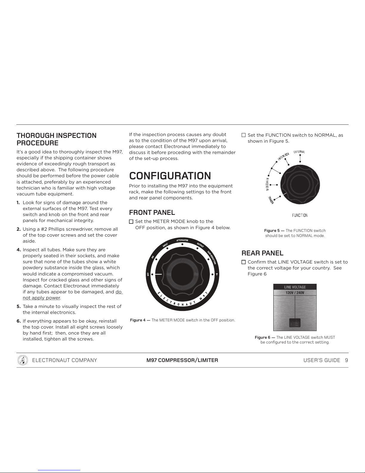
CONFIGURATION
Prior to installing the M97 into the equipment
rack, make the following settings to the front
and rear panel components.
FRONT PANEL
Set the METER MODE knob to the
OFF position, as shown in Figure 4 below.
Figure 4 — The METER MODE switch in the OFF position.
Set the FUNCTION switch to NORMAL, as
shown in Figure 5.
Figure 5 — The FUNCTION switch
should be set to NORMAL mode.
REAR PANEL
Confirm that LINE VOLTAGE switch is set to
the correct voltage for your country. See
Figure 6
Figure 6 — The LINE VOLTAGE switch MUST
be configured to the correct setting.
USER’S GUIDE 10
ELECTRONAUT COMPANY M97 COMPRESSOR/LIMITER
NOTE:
The LINE VOLTAGE switch is old-school and
specifies the voltages as 115 or 230; however,
the intended operating voltages are 120 or
240 volts respectively.
To change the line voltage setting, use a flat
screwdriver to slide the switch to the correct
setting.
The LINE VOLTAGE switch is set at the factory
based on the buyer’s shipping address or by
request at the time of order.
The standard M97 accommodates 120 volt 60
Hz operation, as well as 240V 50 Hz operation.
Electronaut may be able to accommodate
other power line voltages and frequencies
upon request.
NOTE:
Do not operate the M97 with the
LINE VOLTAGE switch in the wrong position!
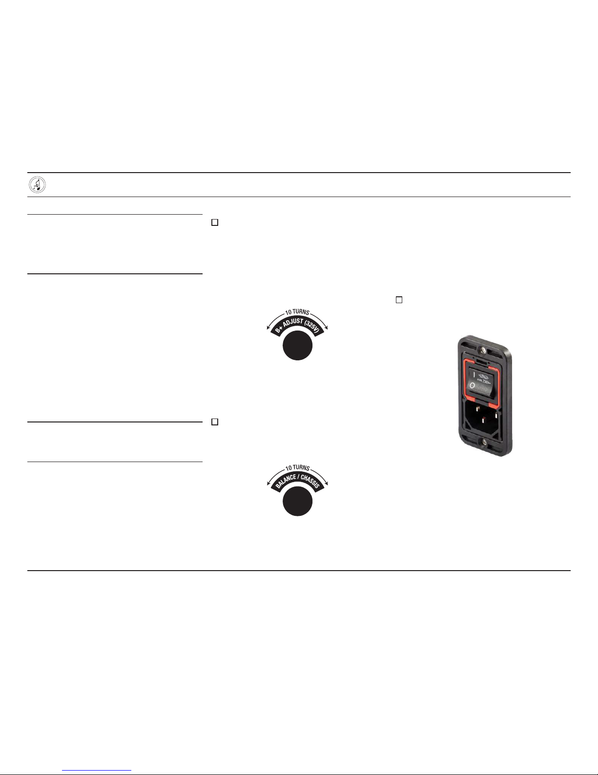
B+ ADJUST (325V) KNOB
Set the B+ ADJUST (325V) knob to its
center position. This is a 10-turn knob;
to find the center, turn the knob in one
direction continuously until it stops, then
turn it back five full rotations. (You can
count the rotation of the brass set-screw on
the top of the knob). See figure Figure 7.
Figure 7 — The B+ ADJUST control permits
adjustment of the high voltage tube regulator.
BALANCE/CHASSIS KNOB
Set the BALANCE/CHASSIS knob to its
center position. This is also a 10-turn knob;
refer to the procedure in the previous step.
Figure 8 — The BALANCE/CHASSIS control is a
secondary balancing control used to fine-tune
the balance the push-pull audio amplifier.
IEC POWER INLET SWITCH
The IEC power inlet includes a switch which
is used to completely disconnect the mains
power from the M97. See ““POWER SCHEME”
on page 29.
The ON position is shown by the symbol “I”,
and the OFF position is shown by the symbol
“O”. See Figure 9 below.
Switch the IEC power switch to the OFF or
“O” position.
Figure 9 — The IEC power inlet, with the
switch shown in the ON position.
USER’S GUIDE 11
ELECTRONAUT COMPANY M97 COMPRESSOR/LIMITER
INSTALLATION
NOTE:
These instructions assume that you will have
access to the rear panel of the M97 after it
has been installed into your rack. If your
rack prohibits rear-panel access, perform the
CALIBRATION procedures before installation.
The M97 is designed to be mounted in a
standard 19” equipment rack, occupying four
units (4U) of rack space. Additional space
above and below is strongly recommended to
ensure adequate airflow around the unit.
A locking IEC power cable is included with
North American versions, but any IEC cable
with a current rating of 5A or higher will work
fine. (See ““IEC POWER CABLE” on page 29 for
stock part numbers).
AIRFLOW AND THERMAL CONSIDERATIONS
The M97 is designed to run fairly cool
considering the number of tubes and the size
of the power supply, but it is normal for the
unit to be warm to the touch. The M97 should
never be so hot as to make it impossible to
leave your hand on the side panels or the top
and bottom covers indefinitely.
Avoid installing the M97 into an equipment
rack shared by other excessively hot
equipment.
To help control the internal temperature, a
very quiet brushless-DC fan is installed on the
rear panel. The fan runs continuously when
the M97 is powered on.
NOTE:
The fan has a service life of 80,000 hours,
equivalent to 18 years of 12 hour-per-day
operation. It should be replaced near the end
of its service life.
Install the M97 into the equipment rack,
making sure to leave adequate space
around the unit for airflow.
Attach the power cable to the IEC power
inlet, and plug it into a power source.
CALIBRATION
For best performance, it is necessary to
calibrate the high voltage power supply as
well as the balance of the audio amplifier. This
calibration procedure should be followed at
the time of installation, then verified from time
to time as needed.
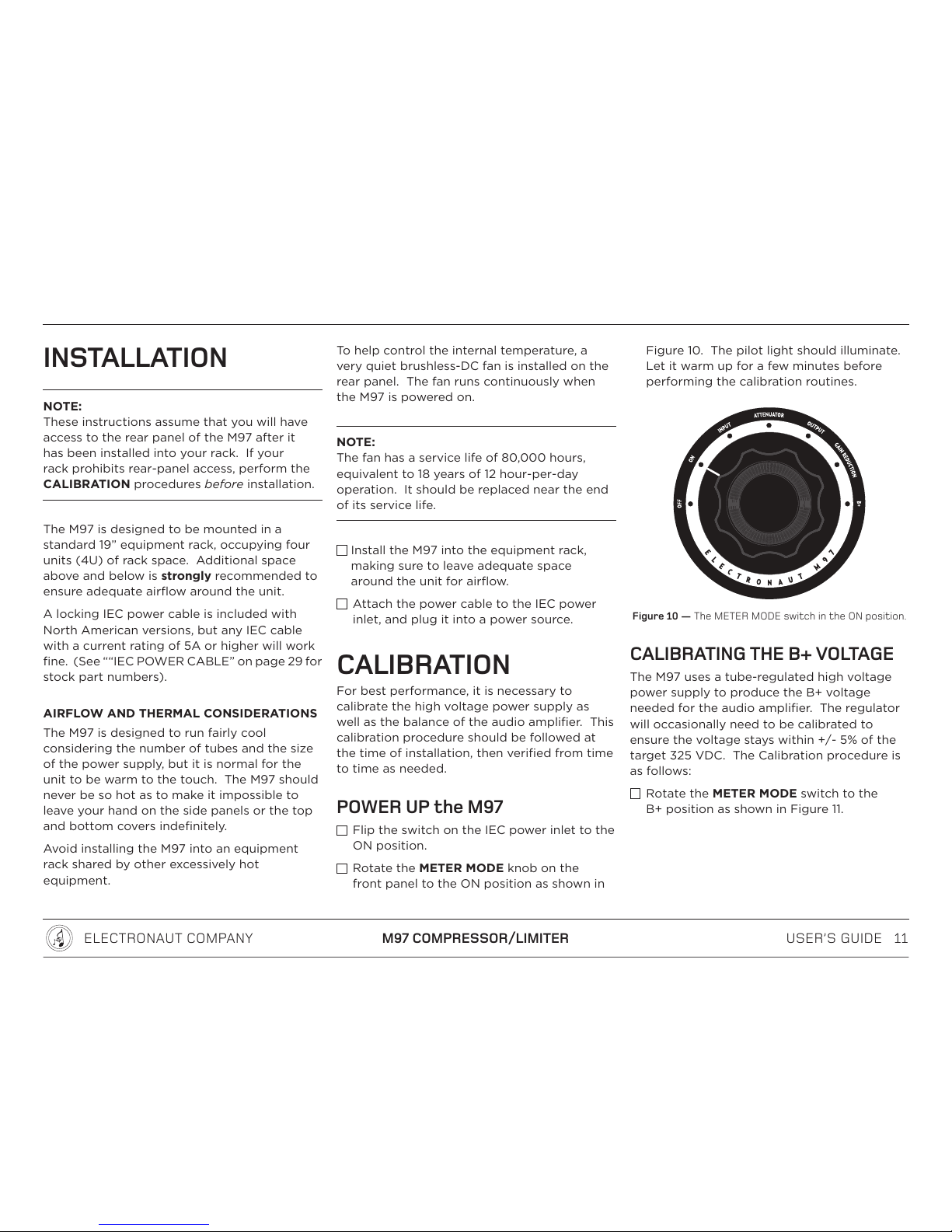
POWER UP the M97
Flip the switch on the IEC power inlet to the
ON position.
Rotate the METER MODE knob on the
front panel to the ON position as shown in
Figure 10. The pilot light should illuminate.
Let it warm up for a few minutes before
performing the calibration routines.
Figure 10 — The METER MODE switch in the ON position.
CALIBRATING THE B+ VOLTAGE
The M97 uses a tube-regulated high voltage
power supply to produce the B+ voltage
needed for the audio amplifier. The regulator
will occasionally need to be calibrated to
ensure the voltage stays within +/- 5% of the
target 325 VDC. The Calibration procedure is
as follows:
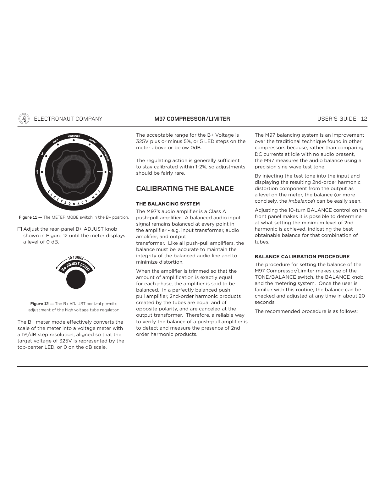
Rotate the METER MODE switch to the
B+ position as shown in Figure 11.
USER’S GUIDE 12
ELECTRONAUT COMPANY M97 COMPRESSOR/LIMITER
Figure 11 — The METER MODE switch in the B+ position.
Adjust the rear-panel B+ ADJUST knob
shown in Figure 12 until the meter displays
a level of 0 dB.
Figure 12 — The B+ ADJUST control permits
adjustment of the high voltage tube regulator.
The B+ meter mode eectively converts the
scale of the meter into a voltage meter with
a 1%/dB step resolution, aligned so that the
target voltage of 325V is represented by the
top-center LED, or 0 on the dB scale.
The acceptable range for the B+ Voltage is
325V plus or minus 5%, or 5 LED steps on the
meter above or below 0dB.
The regulating action is generally sucient
to stay calibrated within 1-2%, so adjustments
should be fairly rare.
CALIBRATING THE BALANCE
THE BALANCING SYSTEM
The M97’s audio amplifier is a Class A
push-pull amplifier. A balanced audio input
signal remains balanced at every point in
the amplifier - e.g. input transformer, audio
amplifier, and output
transformer. Like all push-pull amplifiers, the
balance must be accurate to maintain the
integrity of the balanced audio line and to
minimize distortion.
When the amplifier is trimmed so that the
amount of amplification is exactly equal
for each phase, the amplifier is said to be
balanced. In a perfectly balanced push-
pull amplifier, 2nd-order harmonic products
created by the tubes are equal and of
opposite polarity, and are canceled at the
output transformer. Therefore, a reliable way
to verify the balance of a push-pull amplifier is
to detect and measure the presence of 2nd-
order harmonic products.
The M97 balancing system is an improvement
over the traditional technique found in other
compressors because, rather than comparing
DC currents at idle with no audio present,
the M97 measures the audio balance using a
precision sine wave test tone.
By injecting the test tone into the input and
displaying the resulting 2nd-order harmonic
distortion component from the output as
a level on the meter, the balance (or more
concisely, the imbalance) can be easily seen.
Adjusting the 10-turn BALANCE control on the
front panel makes it is possible to determine
at what setting the minimum level of 2nd
harmonic is achieved, indicating the best
obtainable balance for that combination of
tubes.
BALANCE CALIBRATION PROCEDURE
The procedure for setting the balance of the
M97 Compressor/Limiter makes use of the
TONE/BALANCE switch, the BALANCE knob,
and the metering system. Once the user is
familiar with this routine, the balance can be
checked and adjusted at any time in about 20
seconds.
The recommended procedure is as follows:
USER’S GUIDE 13
ELECTRONAUT COMPANY M97 COMPRESSOR/LIMITER
Turn the AC Threshold knob to its minimum
level (fully counterclockwise) to reduce the
limiting eect to zero. See Figure 13.
Calibrating the balance during linear
operation, when the imbalance is the
biggest contributor to the 2nd harmonic
distortion, yields a more accurate result.)
Figure 13 — The AC THRESHOLD control should be
set to the maximum counter-clockwise position
during the BALANCE procedure..
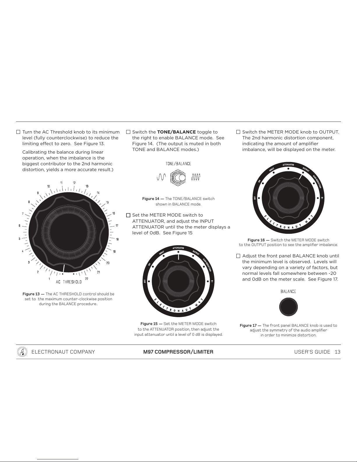
Switch the TONE/BALANCE toggle to
the right to enable BALANCE mode. See
Figure 14. (The output is muted in both
TONE and BALANCE modes.)
Figure 14 — The TONE/BALANCE switch
shown in BALANCE mode.
Set the METER MODE switch to
ATTENUATOR, and adjust the INPUT
ATTENUATOR until the the meter displays a
level of 0dB. See Figure 15
Figure 15 — Set the METER MODE switch
to the ATTENUATOR position, then adjust the
input attenuator until a level of 0 dB is displayed.
Switch the METER MODE knob to OUTPUT.
The 2nd harmonic distortion component,
indicating the amount of amplifier
imbalance, will be displayed on the meter.
Figure 16 — Switch the METER MODE switch
to the OUTPUT position to see the amplifier imbalance.
Adjust the front panel BALANCE knob until
the minimum level is observed. Levels will
vary depending on a variety of factors, but
normal levels fall somewhere between -20
and 0dB on the meter scale. See Figure 17.
Figure 17 — The front panel BALANCE knob is used to
adjust the symmetry of the audio amplifier
in order to minimize distortion.
USER’S GUIDE 14
ELECTRONAUT COMPANY M97 COMPRESSOR/LIMITER
Bear in mind that as the M97 approaches a
perfect balance, the 2nd harmonic is reduced
until it is eventually buried in the noise floor.
At this point the system cannot distinguish
between the 2nd harmonic and the noise, and
the level shown on the display gets “jumpy” as
it tries to track the subtle fluctuations of the
noise floor. This is about as perfect a balance
as is achievable without laboratory equipment.
With perfect tubes, the perfect balance would
be at the center of the BALANCE knob’s
rotational range, or 5 turns from either end-
stop. Real-world tubes will likely require some
other non-center setting.
NOTE:
The absolute value shown on the meter is not
important — it’s the relative value that matters!
The purpose of the calibration is to find the
minimum distortion obtainable for that set of
tubes.
The absolute level can vary by a few dB from
time to time, based on temperature and other
factors. This is normal and should not be of
concern.
It should be mentioned that a precise balance
is a theoretically correct target. For distortion
performance other than minimum, experiment
at will! One advantage of having a precise
balance control is the ease with which a
recalibration for minimum distortion can
be achieved after experimenting with other
settings.
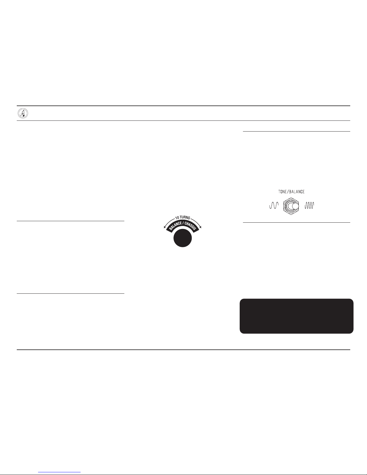
BALANCE/CHASSIS
Most of the time, the BALANCE/CHASSIS
knob should be set to its center position, five
turns in from either end-stop. In rare cases
where mismatched tubes provide some
diculty in obtaining a good balance, the
BALANCE/CHASSIS knob can be employed
for further refinement if necessary.
See Figure 18.
Figure 18 — The BALANCE/CHASSIS control is a
secondary balancing control used to fine-tune
the balance the push-pull audio amplifier.
NOTE:
The engraving on the front panel of the M97
shows both the TONE and BALANCE symbols
as sine waves, but the BALANCE wave is at
twice the frequency. This symbolizes the
function of the BALANCE mode, which is to
detect and display the 2nd harmonic of the
test tone at the output of the audio amplifier.
AT THIS POINT THE M97
SHOULD BE PROPERLY CALIBRATED
AND READY FOR SERVICE

USER’S GUIDE 15
ELECTRONAUT COMPANY M97 COMPRESSOR/LIMITER
REFERENCE
To get the most out of the M97, it is
recommended that the remainder of this
manual be thoroughly read and understood.
INPUT ATTENUATOR
The input attenuator is a high-quality
24-position ELMA switch configured as
a balanced bridged-T network with an
impedance of 600 ohms. The attenuator
is placed between the input XLR and the
input transformer, and provides 1 dB steps
throughout its range, with an “o” mute
function at the most counterclockwise
position.
Once the AC and DC Thresholds and the
Attack and Release controls have been set up,
the degree of limiting can be controlled by
adjusting the input attenuator. See Figure 19.
Figure 19 — The INPUT ATTENUATOR is a 3-pole
23-position balanced bridged-T stepped attenuator.

USER’S GUIDE 16
ELECTRONAUT COMPANY M97 COMPRESSOR/LIMITER
when ZSOURCE = 100 ohms
Figure 20 — The high frequency response can be extended by setting the INPUT ATTENUATOR to zero
and driving the input with a lower impedance source signal, as shown here when driven by a 100 ohm signal.

USER’S GUIDE 17
ELECTRONAUT COMPANY M97 COMPRESSOR/LIMITER
THE INPUT ATTENUATOR and the
HIGH FREQUENCY RESPONSE
The Fairchild 660/670 had a limited high
frequency response, down by several dB at 20
kHz. The primary cause was a low-pass filter
formed by the interaction between the “Miller”
capacitance of the variable-mu tube amplifier
and the impedance of the signal.
What’s “Miller” capacitance?
Vacuum tubes exhibit a tiny amount of
capacitance between the internal electrodes
which is amplified by the gain of the tube,
resulting in an eectively larger capacitance.
This “Miller” capacitance interacts with the
circuit’s impedances, forming a low pass filter
that limits the high frequency response.
A circuit with only one vacuum tube typically
has a small enough Miller capacitance that the
filter has a corner frequency well beyond 20
kHz, having a negligible eect on the sound.
Doubling the number of tubes in the circuit
doubles the Miller capacitance, moving the
corner frequency lower by one octave, and
rolling omore highs.
The Fairchild 660/670 has EIGHT triodes,
adding up to a sizeable capacitance, which
correspondingly moves the corner frequency
to a point within the audible bandwidth.
This was a classic design trade-o, as the
advantage of building a monster compressor
with eight triodes greatly outweighed the
disadvantage of losing a few dB at 20 kHz,
and this gentle high frequency response
characteristic became a part of the Fairchild
sound.
When Electronaut set out to design a modern
“descendent” of the Fairchild 660/670, a
decision had to be made as to whether to
identify this high frequency roll-oas a
problem that should be fixed, or as a feature
that should be preserved. Ultimately, the
point became moot; the M97 can be set to
provide either a Fairchild-like roll-oor a more
modern extended frequency response.
When the INPUT ATTENUATOR is set to any
position other than 0dB, the Miller capacitance
is driven by the attenuator impedance (600
ohms), and the high frequency response is
very similar to the Fairchild 660/670.
When the INPUT ATTENUATOR is set to 0dB,
it is eectively bypassed. This means the
Miller capacitance is driven by the impedance
of the source signal instead of the impedance
of the input attenuator.
Since modern recording systems drive audio
lines at fairly low impedances (often 100
ohms or less), more energy is available to
drive the Miller capacitance when the INPUT
ATTENUATOR is set to 0dB, and this pushes
the pole of the low-pass filter back out to the
ultrasonic range.
Please refer to the frequency response plot
shown in Figure 20.
NOTE:
When setting the INPUT ATTENUATOR to 0dB
for extended high frequency bandwidth, it is
necessary to use a fader or other means to
control the level driving the M97 input, since
the amount of compression is dependent on
input level.
The graph shows several distinct
characteristics:
• With 6dB of attenuation and no
compression, the response is down
approximately 2.5 dB at 20 kHz.
• With the attenuator at 0 dB and no
compression, the response is relatively flat
out to 50 kHz.
The high frequency response is also influenced
to a lesser degree by the limiting action,
which tends to boost the top end slightly,
compensating for the natural roll-o.
• With 6dB of attenuation and 6 dB of
compression, the response is down only
1 dB at 20 kHz.
• With the attenuator at 0 dB and 6 dB of
compression, a boost of nearly 2 dB at 20
kHz can be obtained.

USER’S GUIDE 18
ELECTRONAUT COMPANY M97 COMPRESSOR/LIMITER
THE CONTROLLING AMPLIFIER
DC THRESHOLD
The DC THRESHOLD knob determines at
what level the limiting action begins with the
application of a sine wave or the RMS value
of a complex waveform. Turning the knob
clockwise raises the level at which limiting
action begins. See Figure 21.
Figure 21 — The DC THRESHOLD control raises the
threshold as it is rotated clockwise.
AC THRESHOLD
The AC Threshold is the input attenuator to
the controlling amplifier, which receives its
signal from the output of the audio amplifier.
Used in conjunction with the DC THRESHOLD,
it is set to determine the ratio of compression
during limiting. Turning the knob clockwise
increases the amount of limiter action. See
Figure 22.
Figure 22 — The AC THRESHOLD control increases the
limiter action as it is rotated clockwise.
The AC and DC Threshold are explained
in more detail in the section titled
““UNDERSTANDING the eects of
the AC and DC Threshold controls” on page 20
ATTACK
The attack control determines the speed with
which the limiter attacks a level above the
threshold point, and also determines the ratio
of action the limiter will have on short duration
spikes and transients. Increasing the control
clockwise slows the attack. See Figure 23.
Figure 23 — The ATTACK control slows down the limiter’s
response time as it is rotated clockwise.
USER’S GUIDE 19
ELECTRONAUT COMPANY M97 COMPRESSOR/LIMITER
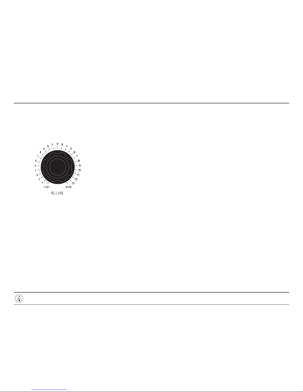
RELEASE
The release control determines the time-rate
of limiter holding action. Increasing the control
clockwise lengthens the holding time. See
Figure 24
Figure 24 — The RELEASE control slows down the
limiter’s recovery time as it is rotated clockwise.
ATTACK and RELEASE INTERDEPENDENCE
The attack and release controls are
interdependent. The attack control provides
a resistance before the time base capacitor
network with the associated release control,
and the input transformer’s center tap feed
network.
In the extreme counterclockwise positions of
the attack and release controls, the limiter is
intended primarily for peak limiting; where it is
desirable to only trim transients and not limit
the basic program material’s dynamic range.
If program level compression is desired in a
ratio greater than 6:1, the attack and release
controls should be set to 7. As the bass
content of the program material increases it
may be necessary to either:
• increase the release control clockwise to
prevent waveform distortion as the limiter
follows the waveform of the program
signal, or
• engage the high-pass switch
There are no cut-and-dry rules to these
settings; they will need to be determined
through experimentation.
THE USABILITY OF THE FASTEST
ATTACK TIMES
The high-powered controlling amplifier in the
M97 can produce large control voltages very
quickly, allowing a good amount of limiting
and very fast attack times approaching
50 microseconds. Very fast attack times
are useful for limiting brief, short-duration
transients. Typically the DC Threshold control
is used at the higher end of its range to ensure
that only the transient peaks are aected.
Due to the nature of the timing circuits and
the controlling amplifier topology, very fast
attack times cannot be sustained indefinitely.
A good analogy to the fast attack limitaiton
is the classic camera flash found in old-school
analog cameras. The flash was capable of
producing an enormous amount of light, but
could only maintain it long enough for the
shutter to expose the frame. Once the energy
was depleted, a period of time was required to
recharge the flash.
Superficially, the fastest ATTACK times are
similar in that they can produce very large
control voltages very quckly, but for a limited
length of time. For this reason they are ideally
suited for fast-transient peak limiting.
Distortion will be obvious if the ATTACK time
is set to its fastest setting (fully counter-
clockwise) and the M97 is set for heavy
limiting.
If distortion, thumping, or other compression
artififacts are audible, slow down the ATTACK
time until the distortion disappears.
SUGGESTED SET-UP FOR TRANSIENT
LIMITING:
Turn on the TONE and increase both DC and
AC THRESHOLD controls clockwise gradually
until an increase of 10 dB to the input
provides an increase of 2dB at the output. It
is necessary to increase the DC THRESHOLD
control to bring the compression curve
closer to flat as the AC Threshold control is
increased.
The design settings for the DC and AC
THRESHOLD controls at an input level of +4
dBu are 14 and 14 respectively.
Once this setup has been configured, the
INPUT ATTENUATOR can be used to control
the amount of limiting action. If heavier
program limiting is desired: increase the
attack and release controls until waveform
tracking and distortion are eliminated.
USER’S GUIDE 20
ELECTRONAUT COMPANY M97 COMPRESSOR/LIMITER
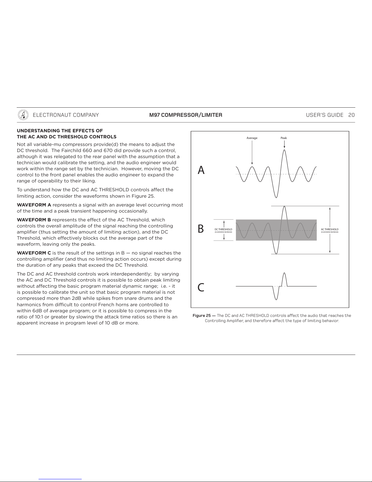
UNDERSTANDING THE EFFECTS OF
THE AC AND DC THRESHOLD CONTROLS
Not all variable-mu compressors provide(d) the means to adjust the
DC threshold. The Fairchild 660 and 670 did provide such a control,
although it was relegated to the rear panel with the assumption that a
technician would calibrate the setting, and the audio engineer would
work within the range set by the technician. However, moving the DC
control to the front panel enables the audio engineer to expand the
range of operability to their liking.
To understand how the DC and AC THRESHOLD controls aect the
limiting action, consider the waveforms shown in Figure 25.
WAVEFORM A represents a signal with an average level occurring most
of the time and a peak transient happening occasionally.
WAVEFORM B represents the eect of the AC Threshold, which
controls the overall amplitude of the signal reaching the controlling
amplifier (thus setting the amount of limiting action), and the DC
Threshold, which eectively blocks out the average part of the
waveform, leaving only the peaks.
WAVEFORM C is the result of the settings in B — no signal reaches the
controlling amplifier (and thus no limiting action occurs) except during
the duration of any peaks that exceed the DC Threshold.
The DC and AC threshold controls work interdependently; by varying
the AC and DC Threshold controls it is possible to obtain peak limiting
without aecting the basic program material dynamic range; i.e. - it
is possible to calibrate the unit so that basic program material is not
compressed more than 2dB while spikes from snare drums and the
harmonics from dicult to control French horns are controlled to
within 6dB of average program; or it is possible to compress in the
ratio of 10:1 or greater by slowing the attack time ratios so there is an
apparent increase in program level of 10 dB or more.
DC THRESHOLD
(CLOCKWISE INCREASE)
AC THRESHOLD
(CLOCKWISE INCREASE)
A
B
C
Average Peak
Figure 25 — The DC and AC THRESHOLD controls aect the audio that reaches the
Controlling Amplifier, and therefore aect the type of limiting behavior.
Table of contents


