INSTALLATION & OPERATING INSTRUCTIONS
1) The unloader is to be positioned on the discharge side of the pumping unit.
2) The bottom port (in) receives the pump discharge.
3) The side port (out) is the pressure outlet. Make sure all side ports are tightened securely.
4) The backside port (bypass) redirects the pumped media when the pressure outlet is closed.
CAUTION: The bypass line must always be open. No shut-ff device is permitted on this side of the unloader.
5) The proper sized bypass line can be directed to a holding tank, to atmosphere, or back to the pump inlet.
NOTE: Bypass lines returning to the pump inlet should be equipped with a thermal relief to prevent excessive
heat buildup in the bypass line that can be damaged the pumping system during periods of prolonged bypass.
CAUTION: Improper placement of the accumulator can affect the unloader capacity of your unloader and can
lead to severe system damage and possible bodily injury.
6) If an accumulator is used as a pulsation dampener in your pumping system, the accumulator must be positioned on the
downstream side of the unloader.
CAUTION: A properly sized pressure gauge must be used when attempting to adjust your unloader to its pres-
sure setting. Position gauge between the pump and unloader.
7) Select the proper spring assembly for your Series 22900 unloader. All spring ratings are based on the maximum operat-
ing pressure of the respective unloaders in the series. See reverse side for ratings.
NOTE: Cracking pressures at which the unloader is activated can rise 300-400 PSI over rated operating pres-
sures depending on your system.
8) Always adjust unloader springs to system pressure with the system open. Be sure before adjusting that the spray
nozzle orice is properly sized for the volume and pressure you desire and then ne tune the unloader.
Adjusting Pressure:
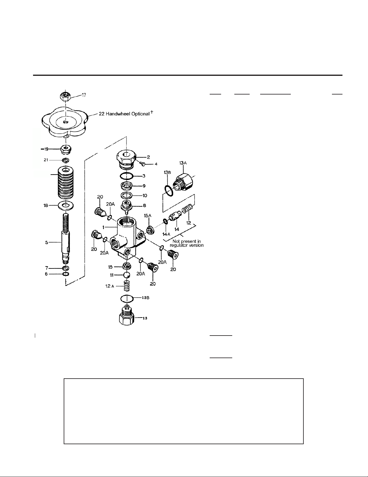
1) Valve should be tension-free, i.e. loosen nut (17) and adjusting nut (19) so that the piston rod can be moved manually.
2) Spring set and adjusting nut (19) -as well as nut (17) on spiral spring design- are to be tensioned while pump is running
and with open gun (in case of more guns, all have to be open) until required operating pressure is reached and no more
water runs out on bypass side. When the nozzle hole coordinates exactly with ow‑rate and pump pressure, no more
water should run over bypass when required operating pressure is reached.
3) Giant Industries, Inc. strongly recommends the use of a pop-off valve positioned between the pump and the unloader
as a safety backup to unloader malfunction.
IMPORTANT!Ifthenozzleholeistoosmalltoallowalltheuidtorunthroughtheholeaftertherequiredoper-
ating pressure has been reached, on no account is the valve to be adjusted higher than the maximum operating
pressure of the pump. In this case, the bypass is to be left paritally open. Nevertheless, it is advisable to have
suitable nozzles installed.
IMPORTANT! The spacer discs (21, 21A) which are under the adjusting nut (16) are there to keep the adjusted
pressure within limits. These discs are not to be removed.
REPAIR INSTRUCTIONS
Renewal of Piston Seals:
Screw guide plug (2) out of casing and remove hexagon screw (4). Remove piston body (8) by turning counterclockwise
with aluminum pliers or tongs (do not use a hard tool). Cut out worn seals. Carefully slide O-ring (6) an support rings (7)
onto piston rod. Note order of installation. Clip sleeve support ring (10) and sleeve (9) onto piston body. Check casing
surfaces and guide plugs (dirt or damage wear seals out quickly). Fasten piston body onto piston rod with Loctite 270.
Grease all parts lightly with Silicone before reinstalling.
To Check Valves:
Screw out plug (13A) and check whether kickback valve taper (14) or kickback valve plate (14) and kickback valve body
(15A) are worn out. Check O-ring (14A) for damage. Remove spring tensioning disc (13) with taper nose pliers and exam-
ine ball (11) and bypass valve body (15) damage. Valve seats can be screwed out with an inserted hexagon key (size 8).
Glue in new valve seats with Loctite 270. Allow to dry for 60 minutes before putting into operation.
Giant Industries, Inc.
900 N. Westwood Ave.
Toledo, Ohio 43607
419-531-4600
Fax: 419-531-6836
www.giantpumps.com Copyright 2015 Giant Industries, Inc.
DEFECT CAUSE REMEDY
Valve switches Leaky gun. Repair gun.
repeatedly when Leaky pressure pipe. Seal pressure pipe.
gun is closed.
Leaky cup. Change cup (9).
Worn out kick-back Change kick-back
valve seat or 0-ring. valve seat (15A) and
O-Ring (14A).
Examine valve seat.
Leaky piston rod. Defective O-Ring/ Change piston rod seals
support Ring. (6,7) and examine
surface of guide plugs.
Leaky bypass at Nozzle too small, Install larger nozzle.
nominal pressure. too much water.
Worn out bypass Examine and change as
valve ball. necessary, ball (11), and
bypass valve seat (15).
Pressure gauge shows Valve set too high Turn back adjusting
high pressure above operating nut (19) and hexagon
uctuations when pressure. nut (17).
shutting off gun. Dirty valve. Clean valve (removing
lime deposits etc.)
Grease parts before
reinstalling.
11/15 22910_22913_22910A_22913A.indd