3
6.Remove the outer access door to the combustion chamber.
7.Disconnect the two (2) wires from the gas control to the high limit switch located
on the right portion of the inner access door to the combustion chamber.
8.Remove the right portion of the inner access door to the combustion
chamber by: first removing the two (2) screws on the right
side of the door and secondly removing the two (2) screws
joining the two (2) pieces together.
9.Disconnect the wire from the spark rod on the pilot
assembly to the piezo ignition button.
10.Unscrew the thermocouple fitting from the gas control.
11.Unscrew the pilot tube fitting from the gas control.
12.Unscrew the gas manifold fitting from the gas control.
13.Remove the burner assembly from the combustion chamber.
14.Separate the burner from the manifold by removing the two (2)
screws on the burner bracket.
15.Remove the natural gas main burner orifice from the manifold tube.
16.Install the propane main burner orifice into the manifold
tube (Supplied in the bag attached to the drain valve).
17.Put the burner back in place by screwing the two (2) screws
on the burner bracket.
18.Replace the pilot assembly set for natural gas with the one supplied
in the bag attached to the drain valve set for propane.
19.Put the burner assembly back into the combustion chamber
ensuring that the flat end of the manifold tube is inserted
in the slot of the manifold bracket welded in the
combustion chamber.
20.Screw the gas manifold fitting into the gas control.
21.Screw the pilot tube fitting into the gas control.
22.Screw the thermocouple fitting into the gas control.
23.Connect the wire from the spark rod on the pilot assembly to the piezo ignition button.
24.If necessary, remove the high limit switch (set for natural gas) on the right portion of the inner access door and
replace it by the high limit switch supplied in the bag attached to the drain valve (set for propane).
Refer to Table 1.
25.Inspect the gasket on the interior side of the door for damage. If damaged,
change the gasket.
26.Replace the right portion of the inner access door to the combustion chamber.
27.Connect the two (2) wires from the gas control to the high limit
switch located on the right portion of the inner access door
to the combustion chamber.
28.Install the outer access door to the combustion chamber.
29.Attach the conversion label to the outside of the
water heater near the rating plate. The label should
be filled out and signed by a qualified installer
or service organization.
30.Return the unused parts to the bag for possible
future conversions.
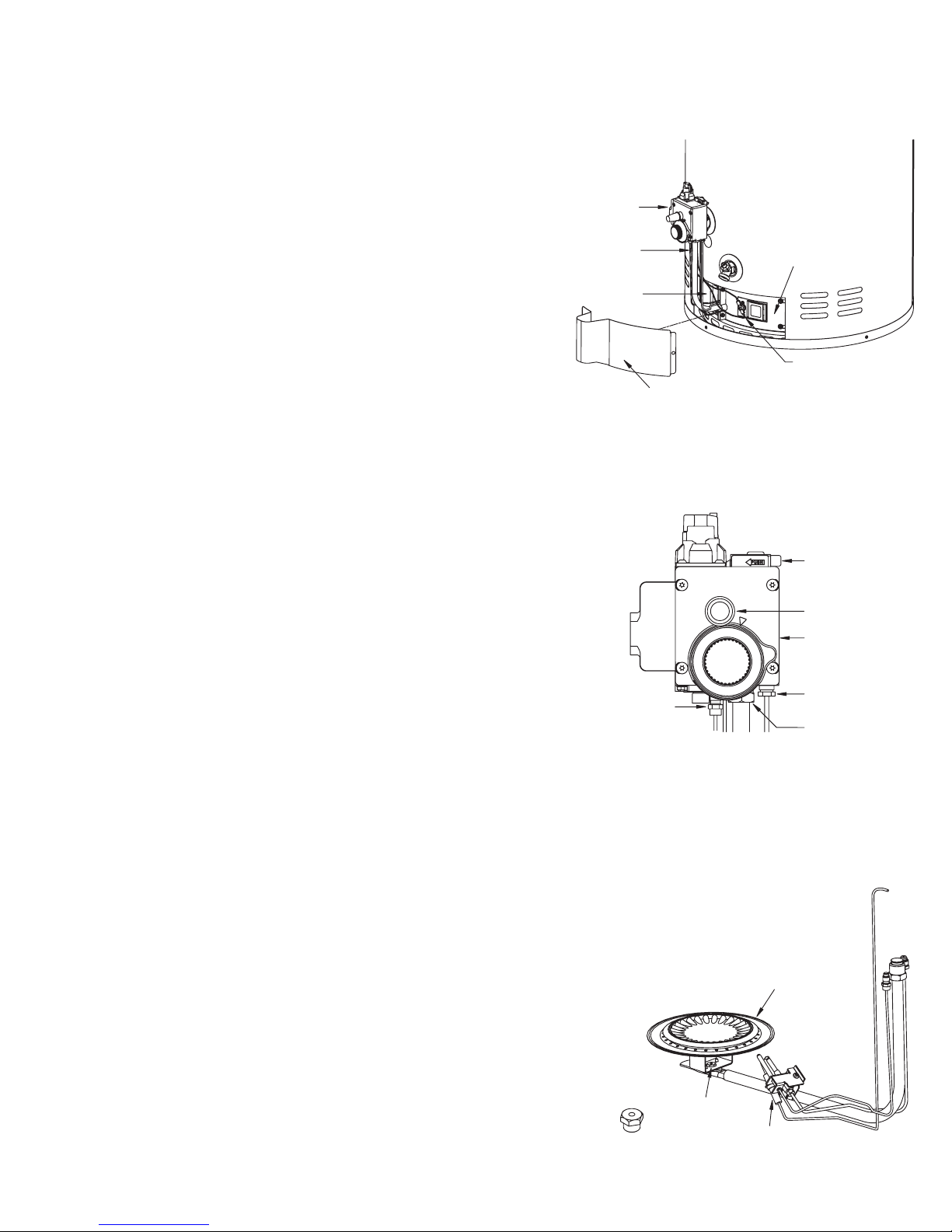
High Limit Switch
(7) (24) (27)
Left Portion
Inner Access Door
Right Portion
Inner Access
Door (8) (25) (26)
Outer Access Door (6) (28)
Burner
Assembly
Gas
Control
Interrupteur
haute température
(7) (24) (27)
Porte d’accès
intérieure gauche
Porte d’accès
intérieure droite
(8) (25) (26)
Porte d’accès
extérieure (6) (28)
Assemblage
du brûleur
Contrôle
au gaz
Burner (14) (17)
Main Burner
Orifice
(15) (16) Pilot
Assembly (18)
Brûleur (14) (17)
Orifice
du brûleur
(15) (16) Assemblage
de la veilleuse (18)
Burner Assembly (13) (19)
Assemblage du brûleur (13) (19)
Piezo
Ignition Button
(9) (23)
Gas Control
Gas Regulator
Thermocouple
Fitting
(10) (22)
Pilot Tube
Fitting (11) (21)
Gas Manifold
Fitting (12) (20)
Bouton d’allumage
piezo-électrique
(9) (23)
Contrôle au gaz
Connecteur
du thermocouple
(10) (22)
Connecteur
de la veilleuse (11) (21)
Connecteur
du tube de gaz (12) (20)
Régulateur de gaz
Gas Control Knob (1)
(Off-pilot-on)
Gas
Regulator
Cap (3) (5)
Gas
Regulator
Manette (1)
d’admission du gaz
(Off-pilot-on)
Capuchon
du régulateur (3) (5)
Vis en laiton (4)
Régulateur
de gaz
Gas Control
Knob Shown In
“OFF” Position (1)
Manette
d’admission du gaz
à la position «OFF» (1)
Brass Screw (4)
Gas Control
Contrôle au gaz


 null")
 null")


 Operation and maintenance instructions")