FF10
2© Gigahertz Solutions GmbH
.Deutsch.
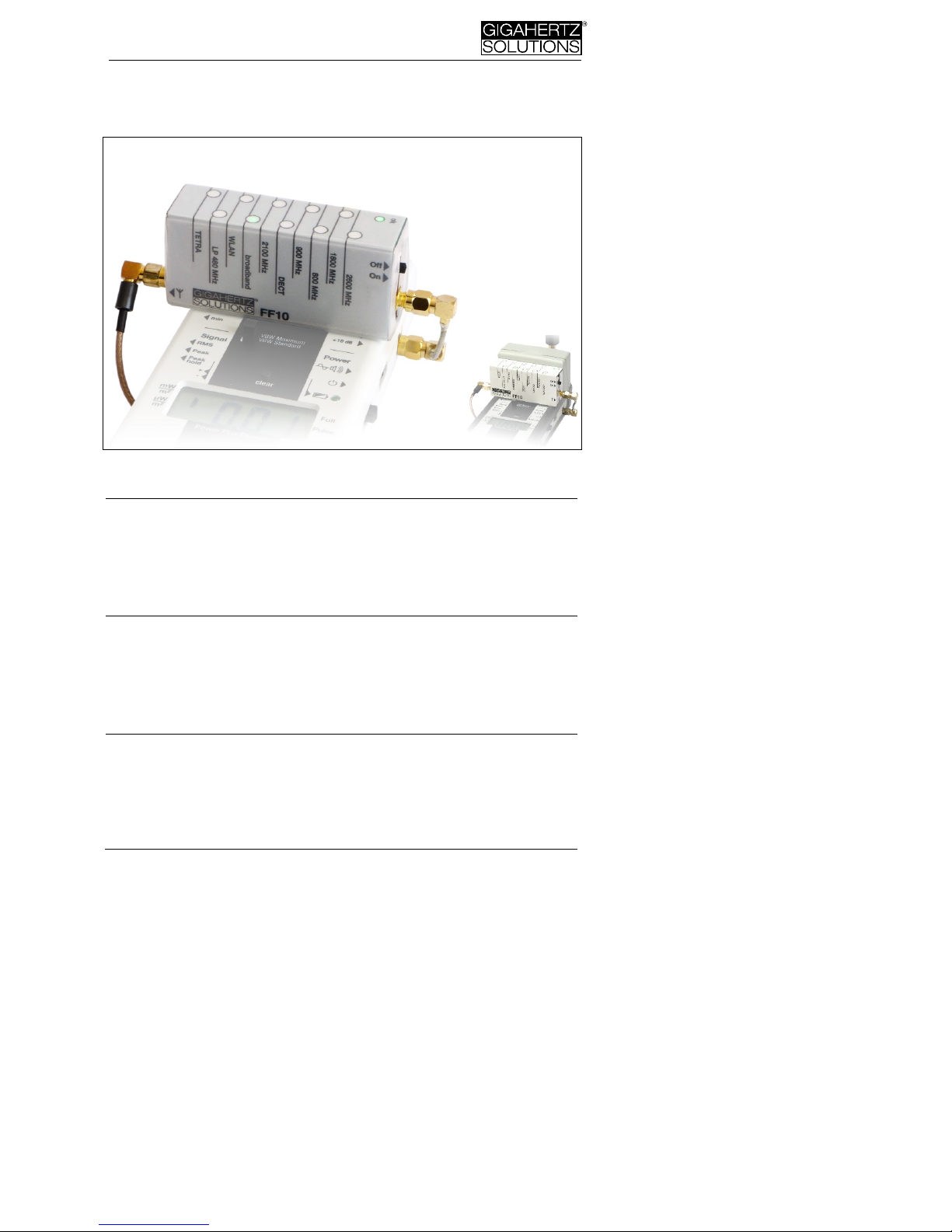
Bedienelemente
Anschlussbuchse für das Antennen-kabel. Kabel
nicht knicken (Kabelführung siehe Seite 4) und Mutter
nicht überdrehen!
On/Off Ein-/Ausschalter (nur für Batteriebetrieb, ohne
Funktion bei Fernspeisung)
ok Leuchtet grün bei ausreichender Stromver-
sorgung.
Das Gerät verfügt im Batteriebetrieb über eine Auto-Power-Off-Funktion. Um
es nach dem Abschalten wieder in Betrieb zu nehmen bitte aus- und wieder
einschalten. Bei Anschluss an den HF Analyser, z.B. für Langzeitaufzeichnun-
gen, ist die Auto-power-Off-Funktion des Filters deaktiviert.
Stromversorgung
Mit einem HF58B, HF58B-r oder HF59B wird die zusätzliche
Batterie des Filters nicht benötigt – der FF10 wird durch den HF-
Analyser mit Strom versorgt. In diesem Fall braucht das Batte-
riegehäuse also nicht montiert zu werden.
Beim HFE35C unterstützt die Filterbatterie diejenige des Mess-
geräts. Beim HF32D, HF35C und HF38B erfolgt die Stromver-
sorgung des Filters ausschließlich über die Batterie im externen
Batteriegehäuse des Filters.
Wenn die „ok“-LED nicht mehr leuchtet, ist eine zuverlässige
Messung nicht mehr garantiert. Wenn auch die Filter-LEDs aus-
gehen, hat die Auto Power Off-Funktion das Gerät abgeschaltet.
Die Auto Power Off-Funktion ist deaktiviert, solange der Filter
vom HF-Analyser mit Strom versorgt wird, z.B. für Langzeitauf-
zeichnungen.
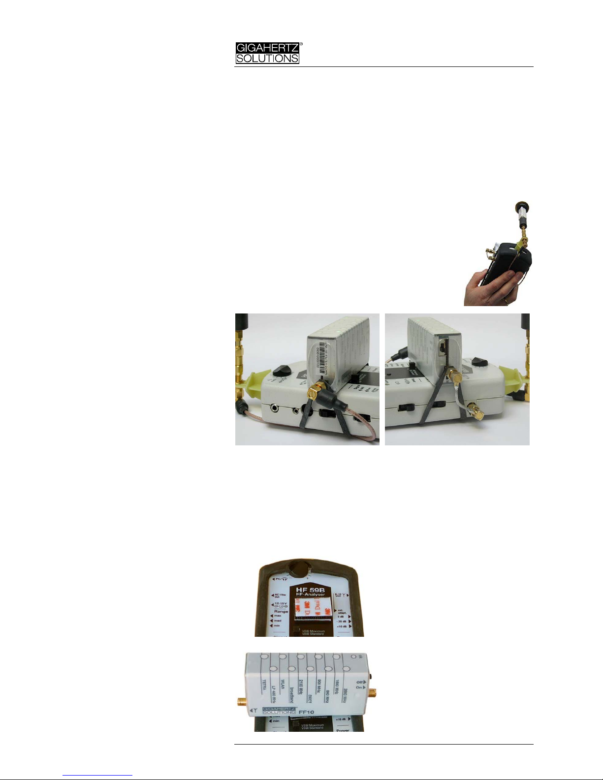
Nur HF35C, HF38B und HFE35C:
Batteriegehäuse montieren
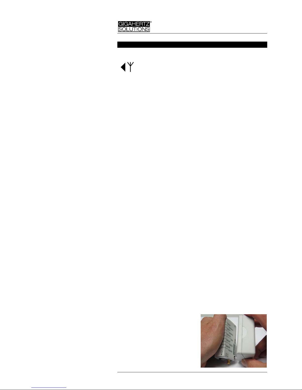
Das externe Batteriegehäuse ist auf der Rückseite mit einer Haft-
folie versehen. Zunächst Schutzfolie abziehen und das Silikon-
schläuchlein zum Schutz der Batteriekontakte entfernen. Vor der
Kontaktierung auf jeden Fall die
Batterie aus dem Gehäuse ent-
fernen!
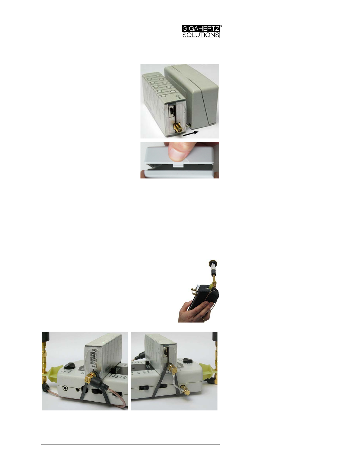
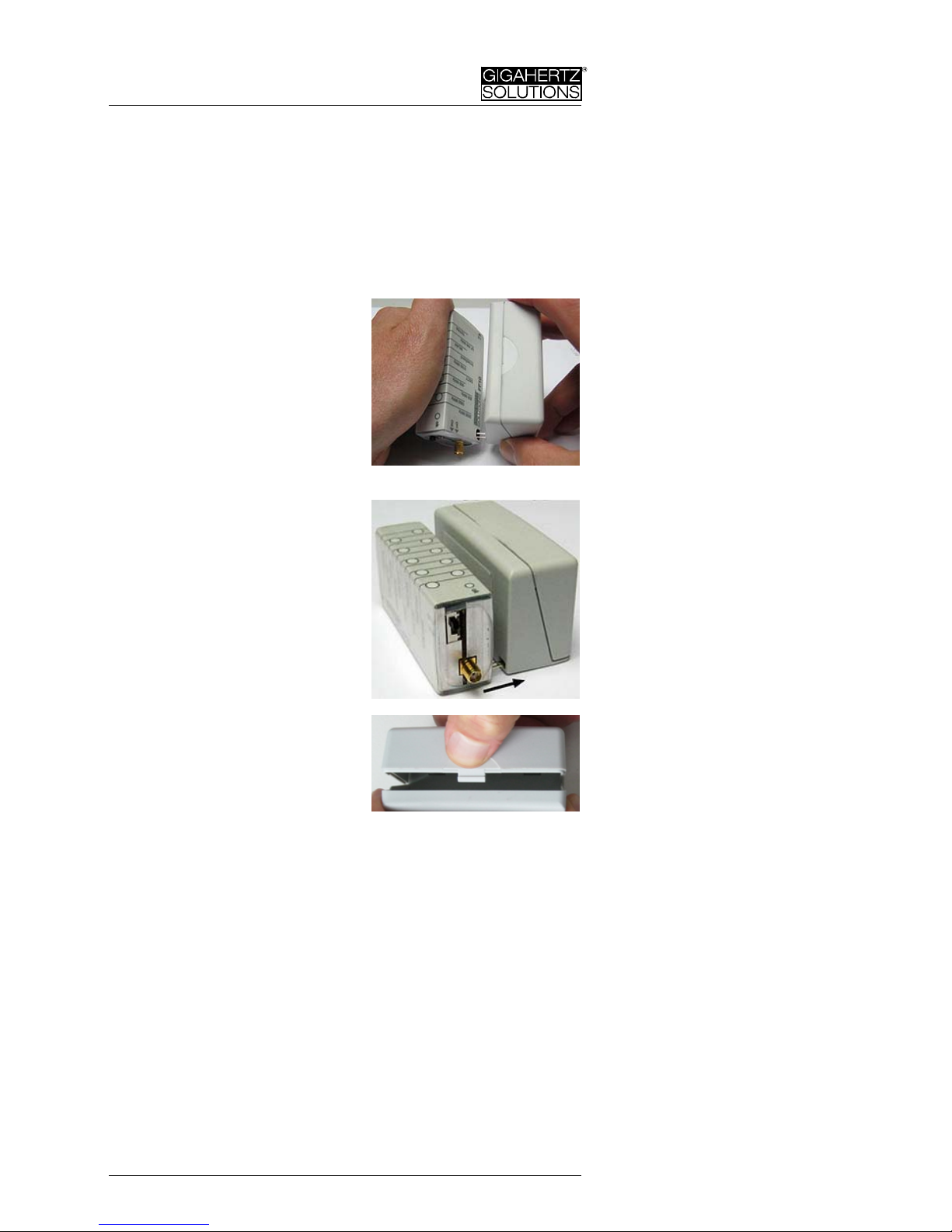
Dann können Sie das Batteriege-
häuse bei Bedarf auf der Rücksei-
te des Filters befestigen, wobei
sorgfältig auf die richtige Kontak-
tierung der Batteriekontakte
rechts unten am Batteriegehäuse