4582
4601
4514
6003
4528-S
4530-S
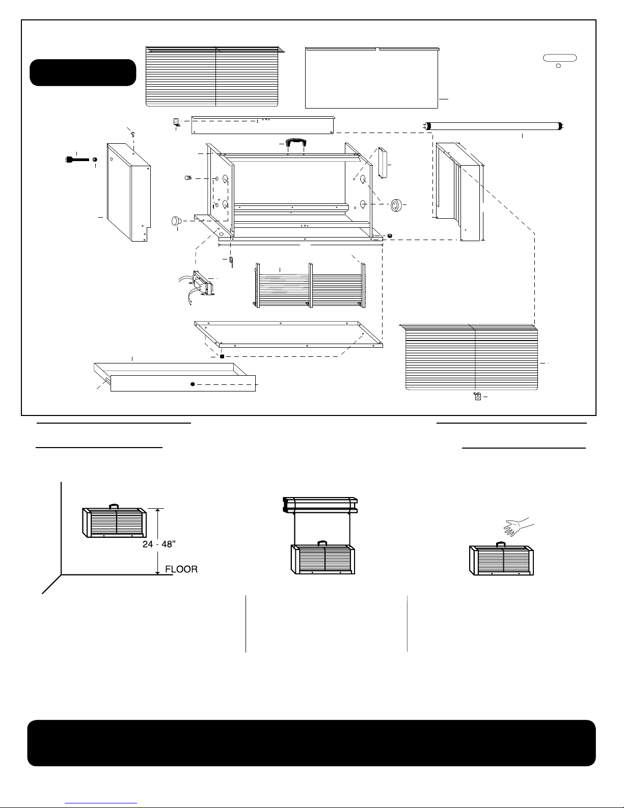
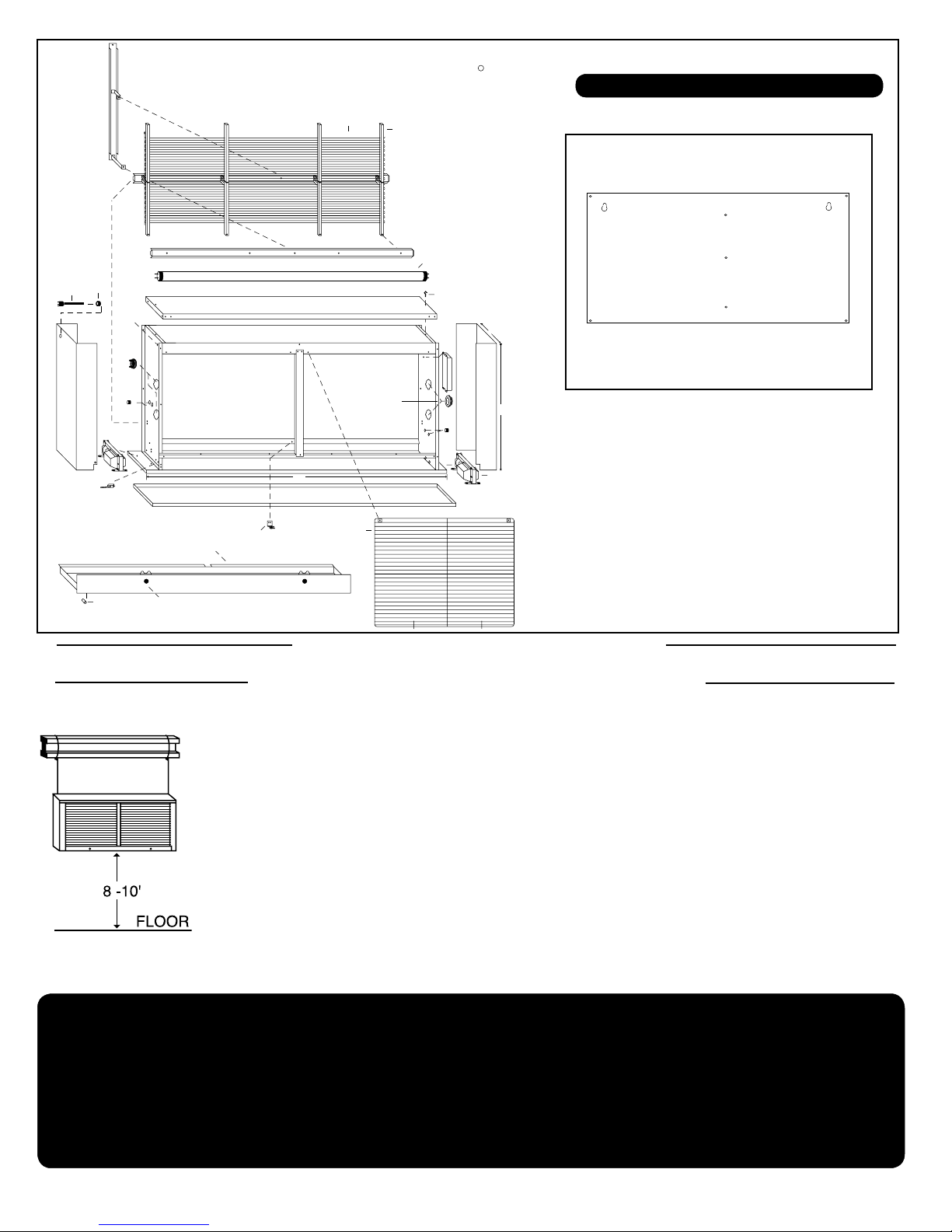
Models 601T-230 Don™, 601E-230 Executive™
INSTALLATION INSTRUCTIONS
1. LAMPS SHOULD BE IN A VERTICAL POSITION WHEN UNIT IS PROP-
ERLY INSTALLED.
2. FOR FLAT-WALL MOUNTING: USING A LEVEL AND PENCIL, DRAW
A STRAIGHT 7" LINE APPROX. 5' ABOVE FLOOR. COME IN 1/4" FROM
ONE END AND MARK ACROSS THAT LINE. MEASURE 5 1/4" FROM
THAT POINT AND MAKE A SECOND MARK. MOUNT THE TWO SCREWS
(PROVIDED) AT THE CROSSPOINTS, LEAVING 1/2" OF THE SCREW
STICKING OUT. SLIDE UNIT ONTO MOUNTING SCREWS AND CONNECT
TO AC POWER.
3. FOR CORNER MOUNTING: USING A LEVEL AND PENCIL, DRAW A
STRAIGHT 8 1/2" LINE FROM THE CORNER IN BOTH DIRECTIONS, AP-
PROX. 5' ABOVE FLOOR. MAKE A CROSS MARK AT THE END OF BOTH
LINES. MOUNT THE TWO SCREWS (PROVIDED) AT THE CROSSPOINTS,
LEAVING 1/2" OF THE SCREW STICKING OUT. SLIDE UNIT ONTO MOUNT-
ING SCREWS AND CONNECT TO AC POWER.
4. AFTER MOUNTING UNIT, OPEN THE GUARD AND PUT THE 2 ADDI-
TIONAL SCREWS (PROVIDED) IN THE 2 SLOTS AT THE BOTTOM.
5. MODELS 601E & 601C (ONLY) MAY BE RECESS MOUNTED IN WALL.
NOTE: IF MOUNTING ON MASONRY, USE A 3/16" BIT (NOT PROVIDED)
AND DRILL OUT THE TWO CROSS MARKS AND INSERT THE TWO PLAS-
TIC ANCHORS (PROVIDED) BEFORE MOUNTING THE TWO SCREWS.
The Don™, Executive™, Custom™ and Junior™
are for use indoors to control ies and other ying
insects. These models have keyhole slots located
on the back for wall or corner installation and should
be mounted 6" to 12" above oor for best results.
To recess mount the Executive™ or Custom™,
remove wing nut at bottom of inner body (which
contains all electrical components), pull out bottom
of inner body, slide down and out. Mount outer case
permanently into wall. Reverse process to insert
inner body.
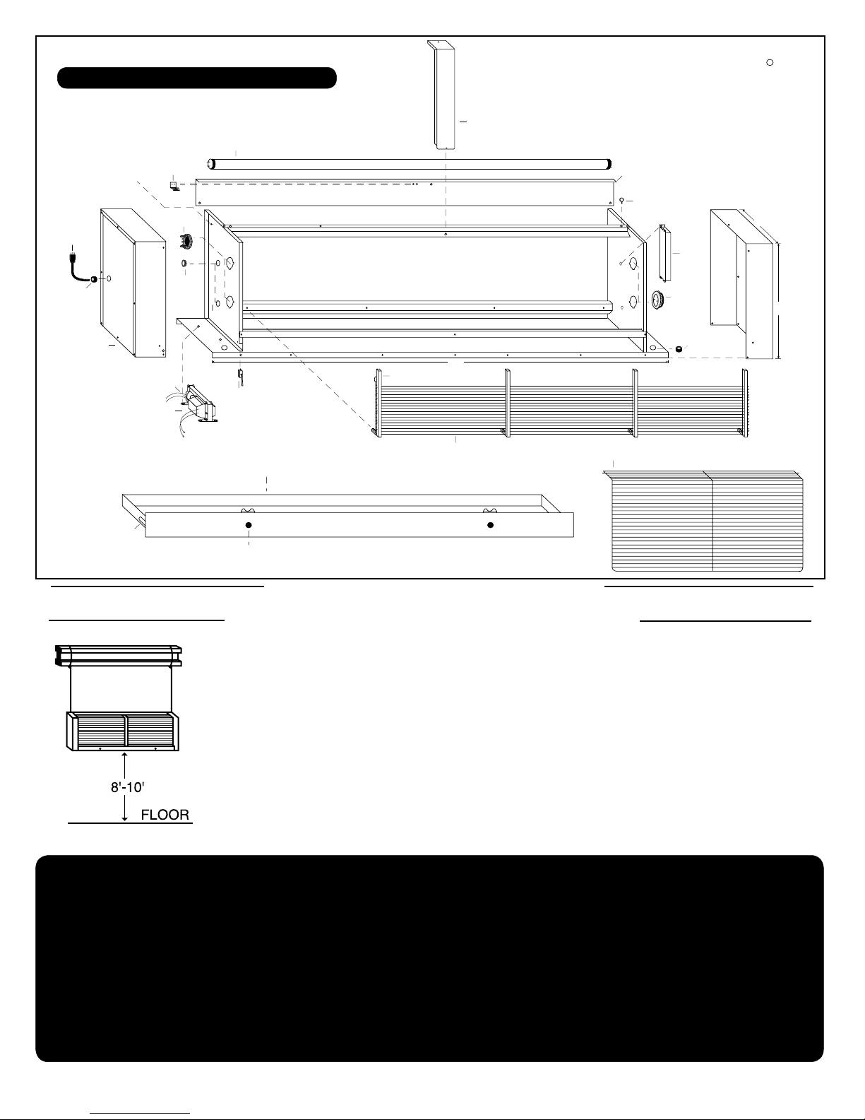
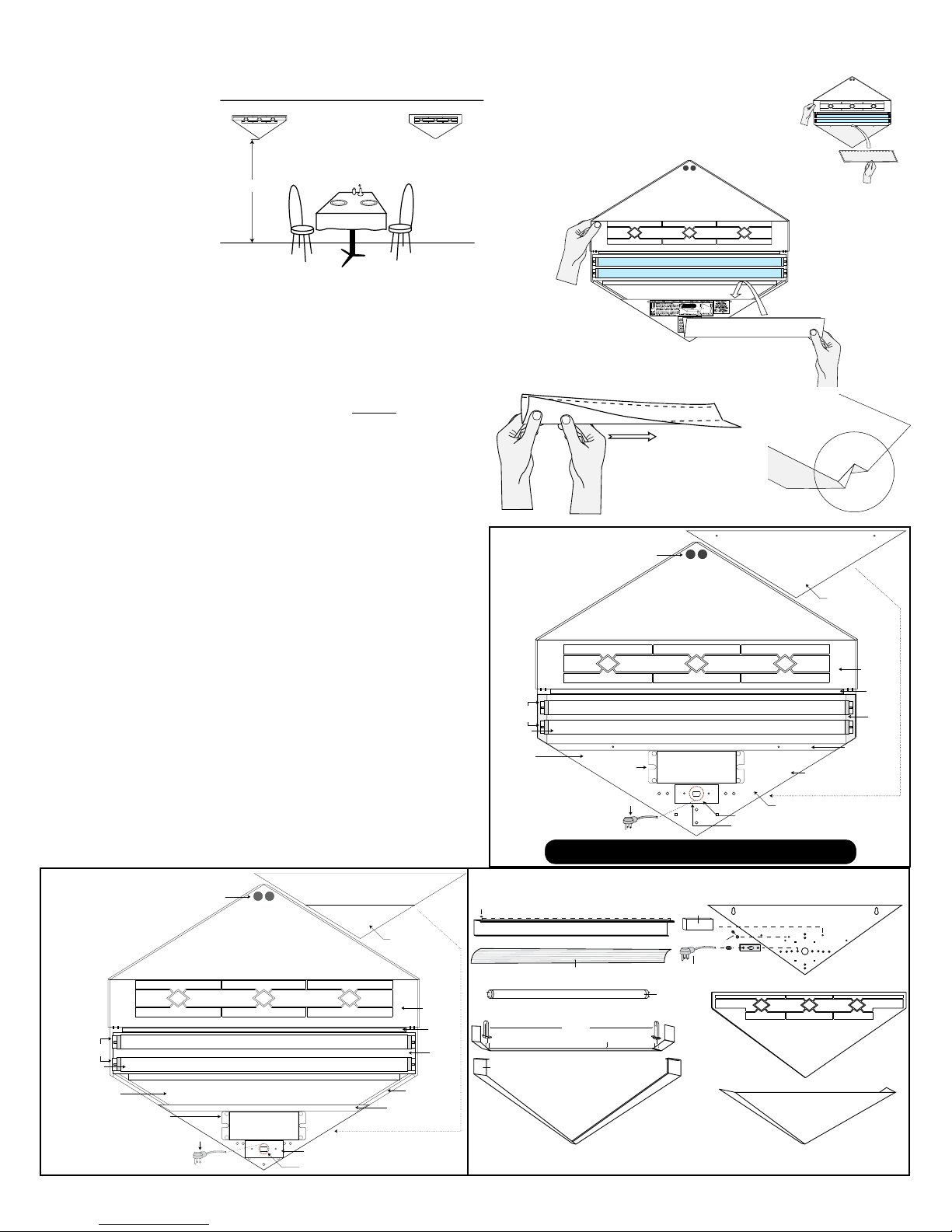
INSTALLATION INSTRUCTIONS
1. LAMPS SHOULD BE IN A HORIZONTAL POSITION WHEN UNIT IS
PROPERLY INSTALLED.
2. USING A LEVEL AND PENCIL, DRAW A STRAIGHT 33" LINE APPROX. 3'
ABOVE FLOOR. COME IN 1/4" FROM ONE END AND MARK ACROSS THAT
LINE. MEASURE 32" FROM THAT POINT AND MAKE A SECOND MARK.
MOUNT THE TWO SCREWS (PROVIDED) AT THE CROSSPOINTS, LEAV-
ING 1/2" OF THE SCREW STICKING OUT. SLIDE UNIT ONTO MOUNTING
SCREWS AND CONNECT TO AC POWER.
NOTE: IF MOUNTING ON MASONRY, USE A 3/16" BIT (NOT PROVIDED)
AND DRILL OUT THE TWO CROSS MARKS AND INSERT THE TWO PLAS-
TIC ANCHORS (PROVIDED) BEFORE MOUNTING THE TWO SCREWS.
The Flying Lion™ is a superior trap to control ies
and other ying insects. Keyhole slots are located
on back for wall installation. Generally speaking,
the lower any trap is placed, the more effective
it is against ies. The Flying Lion™ is normally
mounted 24" above the oor.
Model 711-230 Flying Lion™
4
PROFESSIONAL ELECTROCUTING LIGHT TRAP
INSTALLATION AND APPLICATION
REMOVE ALL PACKING MATERIALS BEFORE INSTALLATION
Traps may be place higher than recommended, however,
the lower any light trap is placed almost always makes it more effective against ies!
See also: gilbertinc.com.strategic.htm
MODEL: Gilbert® 711-230 "Flying Lion"
See Parts List (Page 15) For Part Descriptions