manuals.online logo
Brands
  1. Home
  2. •
  3. Brands
  4. •
  5. Gio Electric
  6. •
  7. Scooter
  8. •
  9. Gio Electric ELEMENT User manual

Gio Electric ELEMENT User manual

ELEMENT
MOBILITY SCOOTER
OWNERS MANUAL - EN
PRIOR TO FIRST USE, READ THIS MANUAL COMPLETELY AND ATTENTIVELY! IMPERATIVELY FOLLOW
THE SAFETY INSTRUCTIONS! NONOBSERVANCE CAN LEAD TO INJURIES! CAREFULLY KEEP THIS
MANUAL!
PLEASE INSPECT YOUR GIO ELECTRIC ELEMENT MOBILITY
SCOOTER UPON ARRIVAL AND REPORT ANY DAMAGES THAT
MAY HAVE OCCURRED DURING SHIPPING
ATTENTION
⚠
This scooter is designed only for one adult only. Never exceed the max
load capacity of the vehicle. 460lbs(209kg)
This scooter is designed for even surfaces with a maximum
recommended incline of 12°
Before using this scooter read this manual carefully. Failure to follow
the instructions herein may result in damage to the scooter or injury to
the driver. Do not let anyone else operate this scooter without reading
this manual prior to use.
⚠
The electronics of this scooter, especially the controller, need to be
kept away from water. Avoid accidental exposure to water while
cleaning the scooter.
When the battery monitor shows under the yellow level, always
recharge the battery. Failure to do so my shorted the life of the battery
Avoid physical contact with the contacts of the charging socket. Shock
may occur, leading to injury.
2
Table of Contents
Diving Safety 3
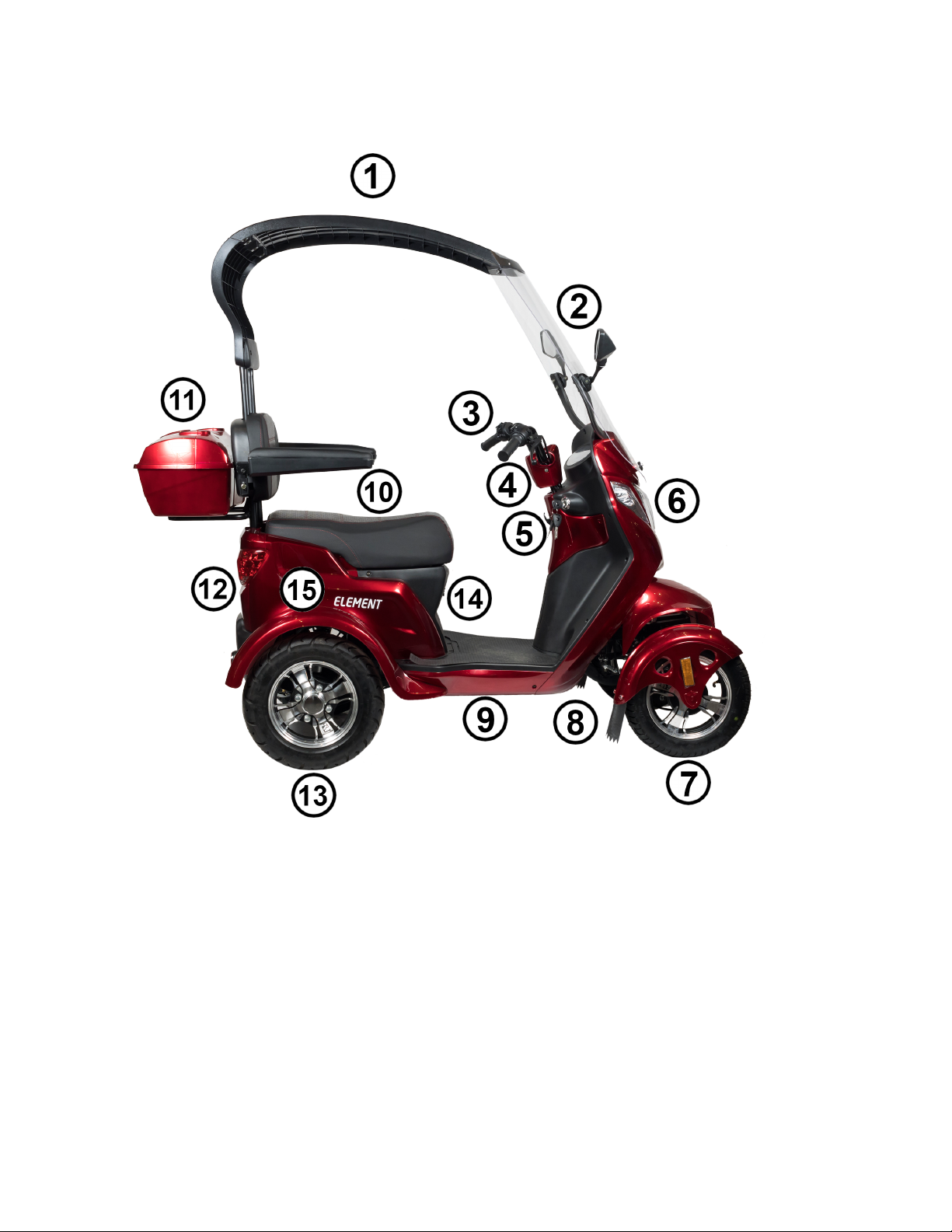
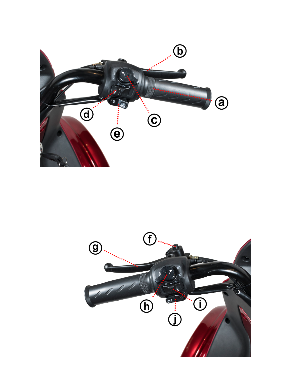
Scooter & Control Diagrams 4
Scooter Assembly 5
Operating Your Scooter 20
Maintenance & Care 22
Specifications & Troubleshooting 24
Warranty Information 26
Driving Safety
Take time to practice and get a feel for your scooter’s handling in a
safe location away from pedestrians and traffic.
Inspect the scooter prior to each use
AVOID driving while fatigued or tired
AVOID driving under the influence of drugs or alcohol
AVOID distracted driving by not using a cell phone while driving
AVOID driving in conditions that may get the electric components wet
AVOID driving off-road or on surfaces that may lead to scooter damage
ALWAYS drive with caution at appropriate speeds
ALWAYS obey local traffic law
ALWAYS be aware of your surroundings, pedestrians, traffic etc
ALWAYS take extra care when driving in spaces shared with motor
vehicles, parking lots, driveways, crosswalks etc
ALWAYS use your lights when driving in darker conditions
3
Scooter Diagram
1) Canopy 9) Footrest
2) Mirrors 10) Seat
3) Handlebars & Controls 11) Storage Compartment
4) Steering column & LCD Display 12) Rear lights/turn signals
5) Ignition Switch 13) Rear wheels/brakes
6) Headlight & Turnsignals 14) Charging port
7) Front wheels/brakes 15) Battery, Controller,
8) Front fender/mud flaps Motor (Internal)
4
Control Diagram
a) Twist Throttle f) Parking Brake
b) Rear Brake Level g) Front brake lever
c) Speed Setting Switch h) Brightness Switch
d) Light On/Off i) Turn Signal Switch
e) Forward/Reverse Switch j) Horn Switch
5
SCOOTER ASSEMBLY
Hardware Guide
(a) 5.5cm M10
(b)4cm M8
(c) 3cm M8
(d) 2.5cm M6
(e) 2cm M6
(f) 4cm M6
(g) 2.5cm M6
(h) 2cm M6
(i) Larger
(j) Smaller
(k)
(l)
(m) M10
(n) M6
(o) Large
(p) Medium
(q)
(r)
Please note that this visual hardware
guide is for comparative reference
only. It is not to scale and actual
hardware may vary in appearance or
size.
(s)
(t) Larger
(u) Smaller
Tool List
You will need a minimum of basics of the following:
Phillips head screwdriver
Wrenches (8mm,10mm,12mm, 14mm, 19mm)
Allen Wrench (5mm)
Pliers
6
Hardware List
Assembly Section
Part
Size
Qty
Handlebars
Bolt
(a) 5.5cm M10
1
Spacer
(l)
1
Nut
(m) M10
1
Fenders & Hood
Phillips Head Bolt
(h) 2cm M6
6
Bolt
(e) 2cm M6
2
Bolt
(d) 2.5cm M6
1
Windshield Brackets
Bolt
(b) 4cm M8
4
Screw
(j) Small
4
Backrest
Bolt
(c) 3cm M8
3
Screw
(i) Bigger
6
Rear Top
Threaded clip
(t) Larger
3
Bolt
(d) 2.5cm M6
3
Bolt
(h) 2cm M6
2
Rooftop
Threaded clip
(u) Smaller
4
Screw
(j) Smaller
4
Windshield
Rubber Grommet
(p) Medium
4
Rubber Grommet
(o) Large
2
Hex Bolt
(k)
2
Aluminum Washer
(q) Large
2
Bolt
(d) 2.5cm M6
3
Rubber washer
(s) Small
3
Metal Washer
(r) Small
3
Nut
(n) M6
3
Mirrors
Phillips Head Bolt
(f) 4cm M6
4
Nut
(n) M6
4
Arm Rests
Bolt
(c) 3cm M8
2
Cargo container
Bolt
(d) 2.5cm M6
5
Nut
(n) M6
5
Steering Cover
Screw
(j) Small
2
7
Assembly Instructions
Your GIO Element arrives partially assembled and requires assembly
before use. For a complete assembly video from our technician
checkout the following video online for the step by step process
https://youtu.be/KeWwoIXZ1lE
To begin assembly, remove the scooter and all pieces from the metal
frame and box it arrived in. It is always best to save all packing
materials until assembly is complete to ensure no component is
accidentally discarded.
1) Wheels
Remove the nut and washer that comes pre installed on each of the
front axles. Lift the scooter and slide on each wheel, making sure to
follow the rotation markings on each wheel to ensure it is on the
correct side. Replace the washer and nut and tighten until secure.
8
Steering Handlebars
Insert the handlebars on top of the steering column aligning the holes.
Insert the large bolt (a) and halfmoon spacer (l) from the front facing
side of the handlebars and align the spacer with the cut out. Secure
the corresponding nut (m) on the bolt and secure using 2 wrenches.
Front Fenders & Hood
To install the fenders, one at a time, place each fender onto the fender
bracket with the mudguard at the rear. Align the fender so the inside
divot is on top of the axle nut and the 3 holes aligned with the threaded
holes on the bracket.
9
Please make sure the cable for the integrated LED lights is on the
outside of the bracket, not between the bracket and tire.
Attach each fender with bolts (h) in each of the 3 holes. Connect the
connector from the fender lights to one of the 3 connectors on the front
end.
To install the hood, first connect the light wire to the last remaining
connector, as making this connection is a bit more cumbersome after
the hood is installed. Align the hole on the front of the hood with the
front bracket and insert and finger tighten the bolt. (d).
10
Next align the side holes on the hood with the side mounting brackets.
Please note the hood may have warped during shipping, if the holes do
not align carefully bend the hood so they do. Once aligned insert bolts
(e) on each side and then tighten them and the front bolt.
Windshield brackets
Remove the windshield bracket cover secured with packing material,
and set aside. Place each bracket in the correct inward position and
install with bolts (b) onto the mounts located behind the removed
cover.
Replace the bracket cover making sure that the lower windshield
mount holes align, and secure from the rear with small screws. (j) You
can now push in the silicon gaskets located on the brackets into
position.
11
Backrest
To install the support for the backrest the seat must be temporarily
removed to attach the support to the frame. First open the seat
compartment by inserting the key into the ignition and turning it to the
left to unlatch it.
With it now unlatched you can lift the seat cushion forward and remove
the 4 bolts holding the underseat tray in position. Carefully set the seat
aside as it will still be attached via the cable on the seat latch. You can
now access the piece of trim that also needs to be removed, remove
all the screws holding it in place.
12
Now is also a perfect time to double check that all the electrical
connections on your scooter are secure. Reconnect any separated
connection or tighten any loose ones. Please note there will be extra
connections on the controller, not used in the function of your scooter.
With the trim removed align the holes on the backrest support with
those on the frame and secure into place with bolts (c). Replace the
trim, making sure it is tucked under the main body(it will not line up
correctly otherwise) and replace the screws holding it in place.
Replace the seat and secure it back into place with the bolts removed
early from the seat tray. At this point check the connections on the
breaker, tightening if necessary, and turn the breaker to the on position,
it will now charge or work otherwise.
13
To complete the backrest the seat cushion and cushion back panel
have to be installed. First attach the back panel by aligning the holes
on the panel with those on the support and screwing (i) into place. Next
align the cushion into place and screw (i) into place through the back
panel.
Rear Top
The first piece of the attached canopy is the rear top section which is
attached to the top of the backrest support. To start, insert the larger
threaded clips (t) into the slots on the rear top piece. Align the now
threaded holes with those on backrest support and bolt into place. (d)
14
To complete this finish on the rear top install the cover over the
mounting connections just installed with bolts(h). (Not pictured)
Rooftop
The rooftop is the next section installed for the scooter’s canopy and
attaches to the previously installed rear top. Insert the smaller clips (u)
into the corresponding slots on the rooftop, align the now threaded
holes with the ones on the rear top section and screw (j) into place.
Please note a second person helping to hold this piece into place while
fastening hardware may be required.
15
Windscreen (Part 1)
The windscreen is the last section of the attached canopy. It attaches
first to the front of the scooter and then to the rooftop. First locate and
install 2 large rubber grommets (p) into the lower holes and 4 (o)
medium rubber grommets into the upper holes. These grommets just
press into place, a screwdriver may be required to push them in
completely.
Secure the windscreen to the 2 mounts below the windshield brackets
with the shiny aluminum washers (q) and hex bolts (k) .
Mirrors
The mirrors for your scooter both attach to the windshield brackets and
secure your windshield into place.
16
Start and place the rubber mirror base grommets on the back of each
mirror. Align the holes of each mirror with the grommet holes on the
windshield and the ones on the windshield bracket.
Secure the mirrors into place with the bolts (f) on the outside, and the
nuts (n) on the inside.
Windscreen (Part 2)
It is now time to connect the windshield to the rooftop, completing the
canopy. First align the holes of the roof top over top of the holes on the
windshield. Then secure each mounting point with a bolt (d) passing
through the following layers and hardware in order; rooftop, small
rubber washer (s), windshield, small metal washer (r), nut (n). Because
the layers are both plastic, carefully tighten all hardware.
17
Arm Rests
Insert each arm rest into the corresponding bracket on the backrest
support and secure it with bolts (c).
Cargo Container
Place the storage container on the mounting plate located on the rear
of the backrest support. Align the holes on the container with those on
the mounting plate and secure with nuts (n) and bolts (d).
18
Steering Cover
Carefully align the 2 halves of the steering handle cover, making sure
all wires pass through wire opening. Slot the 2 halves into place, align
the holes on the cover with threaded holes on the steering handle and
screw (j) into place on both sides.
Your GIO Element should now be fully assembled. The Element
does not arrive fully charged. Please charge before your first use.
19
Operating Your Scooter
Turning your Scooter ON/OFF
To turn the scooter on, insert the key and turn clockwise. To turn your
scooter off, turn the key counterclockwise from the on position.
Driving your Scooter
The Element features a variable twist throttle on the right handlebar. (See
control diagram) Gently twist the throttle grip to slowly accelerate to the
desired speed. Avoid twisting too hard or too quickly as this may result in
jumps in accelerations making steering less controllable.
To slow or stop your scooter, release the throttle and squeeze both brake
levels to apply both front and rear brakes. Always apply both brakes at
the same time, especially when traveling at higher speeds. Please note
the electric braking function of your scooter will prevent the motor from
starting if the brakes are applied.
Drive with care on wet/slippery/icy surfaces as it will increase the distance
needed to stop, allow extra room for braking in these conditions. When
driving downhill it is recommended to release the throttle and apply
brakes as needed to control the scooter’s speed.
Your scooter features control switches next to the throttle grip that adjust
driving features. (See control diagram) The top switch labeled 1-3 sets
the current speed setting of the scooter. The lowest switch marked with D
& R, controls the direction of motion for your scooter. Bring your scooter
to a complete stop before switching between forward and reverse.
(D for Drive to go forward and R for Reverse to move backwards)
The brake lever also features a parking brake option. Once stopped you
can apply the parking brake by squeezing the brake normally and then
pressing in the parking brake button. (See control diagram) To release the
parking brake simply squeeze the brake lever again. Always attempt to
park on a level surface if possible.
20

Other Gio Electric Scooter manuals

Gio Electric WISP User manual

Gio Electric

Gio Electric WISP User manual

Gio Electric Tron User manual

Gio Electric

Gio Electric Tron User manual

Gio Electric TITAN User manual

Gio Electric

Gio Electric TITAN User manual

Gio Electric Italia 500W User manual

Gio Electric

Gio Electric Italia 500W User manual

Gio Electric ITALIA-MK User manual

Gio Electric

Gio Electric ITALIA-MK User manual

Popular Scooter manuals by other brands

PIAGGIO X7 250ie Service station manual

PIAGGIO

PIAGGIO X7 250ie Service station manual

Segway RMP 210 V3 user manual

Segway

Segway RMP 210 V3 user manual

Baotian Classic Service and repair manual

Baotian

Baotian Classic Service and repair manual

Electric Mobility Eco 4 Owners manual & service record

Electric Mobility

Electric Mobility Eco 4 Owners manual & service record

APRILIA ATLANTIC 125 - 05-2003 manual

APRILIA

APRILIA ATLANTIC 125 - 05-2003 manual

Curv S14 user manual

Curv

Curv S14 user manual

Shoprider TE-9 user guide

Shoprider

Shoprider TE-9 user guide

Razor A 5 Lux owner's manual

Razor

Razor A 5 Lux owner's manual

ForU k-lite user manual

ForU

ForU k-lite user manual

Ducati PRO-I PLUS user manual

Ducati

Ducati PRO-I PLUS user manual

Authentic Sports & Toys Muuwmi owner's manual

Authentic Sports & Toys

Authentic Sports & Toys Muuwmi owner's manual

Dualtron REPTOR II user manual

Dualtron

Dualtron REPTOR II user manual

FREESKY Himalaya user manual

FREESKY

FREESKY Himalaya user manual

Drive Viper user manual

Drive

Drive Viper user manual

Drive Medical S35010 owner's manual

Drive Medical

Drive Medical S35010 owner's manual

Trevi VELOCIPTOR ES 100W user guide

Trevi

Trevi VELOCIPTOR ES 100W user guide

aventon SINCH ST quick start guide

aventon

aventon SINCH ST quick start guide

RATTAN LF PRO Series user manual

RATTAN

RATTAN LF PRO Series user manual

manuals.online logo
manuals.online logoBrands
  • About & Mission
  • Contact us
  • Privacy Policy
  • Terms and Conditions

Copyright 2025 Manuals.Online. All Rights Reserved.