Gio Pelle 16 Series Installation instructions

Operator & Owner’s Manual
Aesthetic Procedure Chair
Gio Pelle
SKIN CARE

2
Thank you for purchasing the Gio Pelle Aesthetic Procedure Chair. This precision designed piece of equipment, engineered with you
in mind, will provide many years of trouble free operation. It will save time and increase your ability to service your client in ways you
never believed possible.
Please read carefully and understand this owner’s manual before proceeding. Be sure to thoroughly familiarize yourself with the
operation of the equipment prior to using it.
We appreciate your business and believe the performance, value and reliability of our equipment will earn your trust.
Sincerely,
Table of Contents
Gio Pelle, Inc. reserves the right to incorporate any modications or improvements in machines and machine specications which it considers necessary and does not assume
any obligation to make these said changes in machines and equipment previously sold. The information in this document is subject to change without notice and does not
represent a commitment on the part of Gio Pelle, Inc. No part of this document may be reproduced or transmitted in any form or by any means, electronic or mechanical,
including photocopying, for any purpose without the express written permission of Gio Pelle, Inc.
Unpacking Your Aesthetic Chair................................................................................................................................................... 3
Inspection Checklist .......................................................................................................................................................................... 3
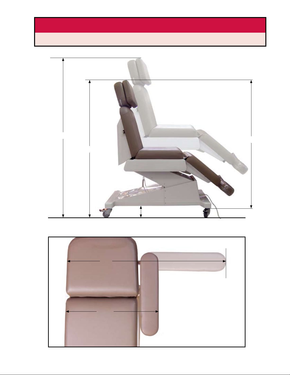
Aesthetic Chair Dimensions........................................................................................................................................................4-5
Attaching Aesthetic Chair Parts & Accessories............................................................................................................... 6-13
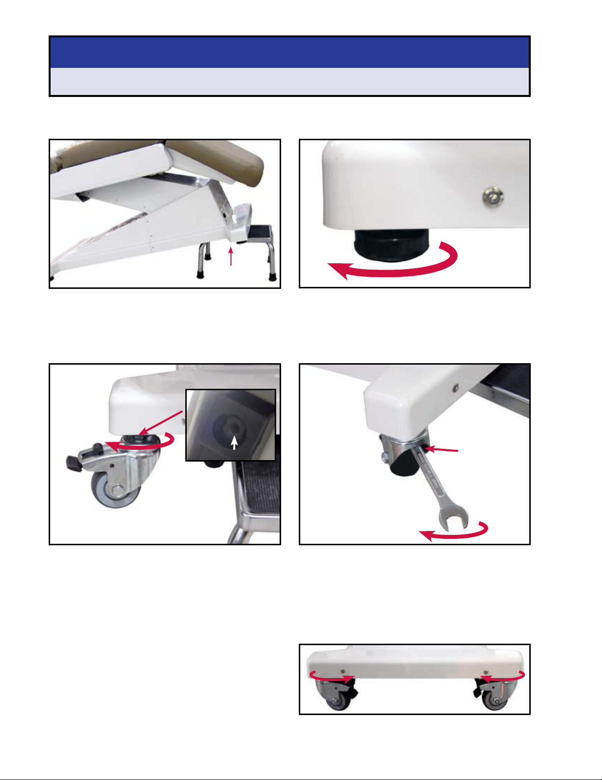
Attaching Wheels........................................................................................................................................................................ 6
Attaching Gliders ........................................................................................................................................................................ 7
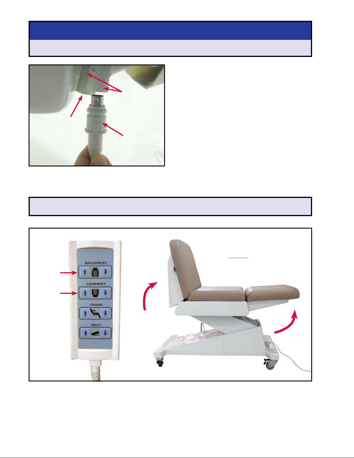
Connecting the Power Cord ................................................................................................................................................... 7
Attaching Hand Control & Foot Control............................................................................................................................. 8
Adjusting Chair Backrest & Legrest ...................................................................................................................................... 8
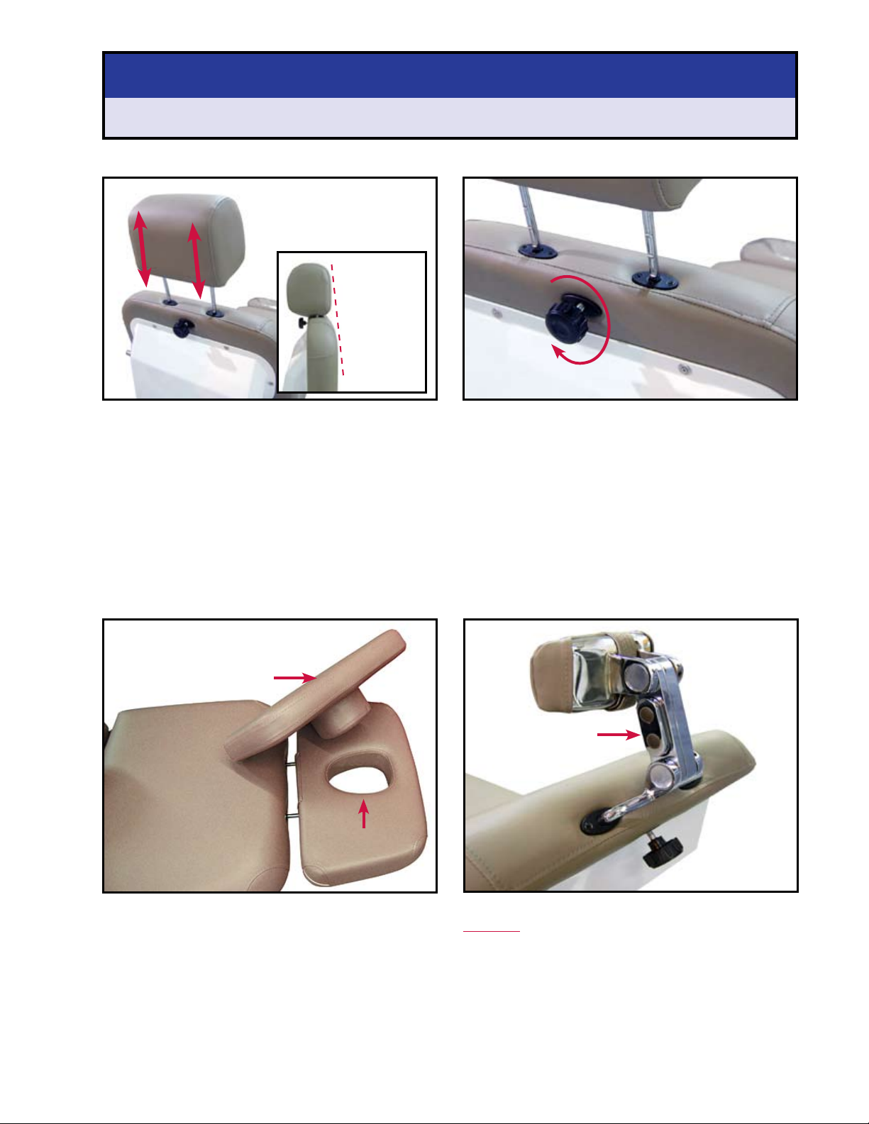
Attaching Headrests .................................................................................................................................................................. 9
Attaching Footrest....................................................................................................................................................................10
Attaching Armrests ..................................................................................................................................................................10
Attaching Paper Holder..........................................................................................................................................................11
Attaching Armboard Kit.........................................................................................................................................................12
Attaching Rails and Stirrups..................................................................................................................................................13
Operating Aesthetic Chair......................................................................................................................................................14-19
Backrest Up / Down .................................................................................................................................................................14
Footrest Up / Down..................................................................................................................................................................15
Chair Up / Down........................................................................................................................................................................16
Seat Up / Down..........................................................................................................................................................................17
Locking the Wheels..................................................................................................................................................................18
Adjusting Armrests / Armboard ..........................................................................................................................................18
Using the Paper Holder ..........................................................................................................................................................19
Using the Multi-Use Power Outlets....................................................................................................................................19
Maintenance.........................................................................................................................................................................................20
Troubleshooting.................................................................................................................................................................................21
Weights & Electrical Specications ...........................................................................................................................................22
Notes........................................................................................................................................................................................................23
Warranty.................................................................................................................................................................................................24
Joanne Bianchini
President Gio Pelle, Inc.

Unpacking Your Aesthetic Chair
3
Inspection Checklist
Your chair should look like the photo shown below when removed from the shipping box.
You will need to attach the parts shown in the “Inspection Checklist” to the chair.
Your chair may include these parts which were purchased for an additional cost
Every Aesthetic Procedure Chair includes the parts shown below
and were included in the purchase price.
4 Casters
4 Gliders
Paper Roll
Large Headrest with
Cut-out Cushion
Foot Control
Footrest
with Slip Cover
Hand Control
Small
Headrest
Articulating
Headrest
4 Leveling Feet
(factory installed
and on chair)
2 Armrests
(one right/one left)
1. Carefully unpack your Aesthetic Chair. Pay special attention not
to damage any parts or upholstery with box knives or other
tools during the unpacking process.
2. Use the checklist below as you unpack each Aesthetic
Chair part.
NOTE: If any of the parts shown below are missing or
have been damaged during shipping please contact
Gio Pelle, Inc. at 800-428-1610.
Dual Outlets
Single Outlets
Armboard Kit (1 armboard)
Armboard Kit (2 armboards)
Paper Holder
(2 brackets, 4 Phillips screws & washers)
Power Cord
Stirrup Kit
(2 stirrups, 2 stirrup brackets,
2 side rails, 4 bolts, 4 spacers,
2 set screws)

Aesthetic Chair Specications
Dimensions
4
4"
57"
75"
20" 20" 16 ½" 7"11"
32 ½” 24"
84"
29"
25" 37"
33"

Aesthetic Chair Specications
Dimensions
5
57"
60"
51"
31 1/2"
4"
53"

Attaching Aesthetic Chair Parts & Accessories
Part 1: Attaching Wheels
6
1. Elevate one end of the chair about 12 inches.
2. Chair needs to rest on something sturdy that will not
move (like the step stool shown in photo).
PART 1/STEP 1: Elevate One End of Chair
1. Remove the factory installed Leveling Feet by rotating
them COUNTER CLOCKWISE.
2. Repeat for other leveling feet.
PART 1/STEP 2: Remove Leveling Feet
Lift about 12”
o ground
PART 1/STEP 5:To connect wheels to opposite
side of chair repeat Steps 1 through 4.
Helpful Hint: Turn wheels parallel to frame of chair so they
are not in the way during procedures.
PART 1/STEP 3: Attach Wheels to Chair
1. Insert male threads on top of the casters into the female
connectors on the bottom of the chair legs.
2. Hand tighten wheel assembly by turning it CLOCKWISE
until assembly no longer turns.
Male threads on wheels attach
to female connectors on bottom of chair legs
Female Connector
1. Use an 11/16" inch wrench to nish securing the wheel
assembly to the chair legs.
CAUTION: Casters must be securely attached to chair
WITHWRENCH to prevent personal injury and/or damage
to chair
2. Lower chair end.
Wrench inserts
between wheel
and metal caster
assembly to nish
tightening screw
to chair legs
SKIP TO PART 2 IF YOU DID NOT PURCHASE WHEELS
PART 1/STEP 4: Secure Wheel with Wrench

Part 3: Connecting Power Cord
Attaching Aesthetic Chair Parts & Accessories
Part 2: Attaching Gliders
7
Male threads on glider attaches
to female connectors on bottom of chair legs
Female Connector
SKIP TO PART 3 IF YOU DID NOT PURCHASE GLIDERS
Step 4: To connect gliders to opposite side
of chair repeat Steps 1 through 3.
PART 2/STEP 3: Attach Gliders to Chair
1. Insert male threads of the glider into the female
connectors on the bottom of the chair legs.
2. Hand tighten glider by turning it COUNTER CLOCKWISE
until it no longer turns.
3. Lower chair end.
1. Elevate one end of the chair about 12 inches.
2. Chair needs to rest on something sturdy that will not
move (like the step stool shown in photo).
PART 2/STEP 1: Elevate One End of Chair
1. Remove the factory installed leveling feet by rotating
them COUNTER CLOCKWISE.
2. Repeat for other leveling feet.
PART 2/STEP 2: Remove Leveling Feet
PART 3/STEP 1: Plug Cord into Chair
1. Plug power cord into connector located on the base of
the chair.
PART 3/STEP 2: Plug Cord into Wall
2. Plug the three prong end of the power cord into a
properly grounded wall outlet supply 110vac (or 220vac
depending on model).
WARNING:
Failure to plug power cord into a properly grounded
electrical outlet with the correct voltage can result in
damage to the chair.
Power Cord
connects to
base of chair
Lift about 12”
o ground
Wall Outlet

Attaching Aesthetic Chair Parts & Accessories
Part 4: Attaching Hand Control and Foot Control
Part 5: Adjusting Chair Backrest & Legrest
8
PART 5/STEP 1: Adjust Backrest
1. Push the“BACKREST UP ARROW BUTTON” on the hand
control until backrest is in the upright position.
PART 5/STEP 2: Adjust Legrest
2. Push the“LEGREST UP ARROW BUTTON” on the hand
control until legrest is in the upright position.
Backrest
UP Button
Legrest
UP Button
It is recommended that the chair
be placed into the position shown
below BEFORE attaching additional
parts and accessories.
Hand Control Plug
Pigtail Adapter Plugs
PART 4/STEP 1: Plug Hand Control into Chair
1. Insert hand control plug into one of the two pigtail
adapter plugs located under the seat and behind the
left side panel trim.
PART 4/STEP 2: Plug Foot Control into Chair
1. Insert foot control plug into the other pigtail adapter
plug located under the seat and behind the left side
panel trim.
NOTE: There are two pigtail adapter plugs. The hand
control and foot control can be plugged into either pigtail
plugs.
Attach foot control plug
into the other
pigtail adapter plug
(NOTE: There are two
pigtail adapter plugs.
The hand control and
foot control can be
plugged into either
pigtail plugs)

Attaching Aesthetic Chair Parts & Accessories
Part 6: Attaching Headrests
9
Large Headrest Helpful Hint
The large headrest cushion contains a cut-out for prone
position procedures. Lift the top part of the cushion away
from the bottom part of the cushion to reveal the face
cut-out.
Articulating Headrest Helpful Hint
Articulating Headrest adjustment button MUST be on the
LEFTSIDE of the chair when attaching it to the backrest.
If attached to chair with adjustment button on the right
side, headrest will not work properly.
Adjustment
Button
Top section of
large headrest
Bottom section of large
headrest features
cut-out
HELPFUL HINTS
PART 6/STEP 1: Attaching Headrests to Chair
1. Carefully slide one of the headrests into the backrest of
the Aesthetic Chair.
2. Headrests can be can be adjusted for patients height
by sliding it closer to or away from the backrest.
Headrest can be positioned
to accommodate patient’s
height
Hand tighten knob to
secure to chair
PART 6/STEP 2: Secure Headrest
1. Hand tighten knob located on back of backrest to secure
headrest to backrest after the headrest is positioned for
patient comfort.
If needed, the
small headrest
can be reversed
so it is ush
with backrest
of chair

Attaching Aesthetic Chair Parts & Accessories
Part 7: Attaching Footrest
PART 7/STEP 3: Secure Armrest to Chair
1. Hand tighten thumbscrew back onto chair post by
turning it CLOCKWISE to secure armrest to chair.
1. Remove thumbscrew from armrest post by turning it
COUNTER CLOCKWISE.
PART 8/STEP 1: Remove Thumb Screw
1. Slide armrest onto post.
PART 8/STEP 2: Attach Armrest to Chair
Part 8: Attaching Armrests
10
PART 7/STEP 4:To connect armrest to opposite
side of chair repeat Steps 1 through 3.
Upholstery zipper must be
face down when attaching.
If zipper is facing up the
armrest is being installed on
the wrong side of the chair
and will not work correctly.
Right side
armrest
Left side
armrest
PART 7/STEP 2: Secure Footrest
1. Carefully slide the footrest into the legrest of the
Aesthetic Chair.
2. Footrest can be can be adjusted for patients height by
sliding it closer to or away from the legrest.
1. Hand tighten knob located on bottom of legrest to
secure footrest to legrest after the f ootrest is positioned
for patient comfort.
Footrest can be positioned
to accommodate patient’s
height
Hand tighten knob to
secure to chair
Add petroleum jelly
to armrest posts if
armest does not
slide on easily or if
armrests squeak
when rotated.
PART 7/STEP 1: Attaching Footrest

Attaching Aesthetic Chair Parts & Accessories
Part 9: Attaching Paper Holder
11
PART 9/STEP 1: Remove Backrest Screws
1. Use a Phillips screwdriver to remove the screws and
washers located at the top of the backrest just under
the headrest.
NOTE: Do not lose the screws and washers. You will need
them to when attaching the paper holder.
PART 9/STEP 3: Create New Pilot Holes
PART 9/STEP 2: Attaching Bottom Brackets
Brackets Paper Holder
Reattach
screw & washer
from Step 1
NOTE: You will need to create pilot holes for the top screws
to t into.
1. Place one of the screws and a washer (included with
bracket) into one of the top bracket holes.
2. Using a power screwdriver, slowly secure the screw
into the chair back upholstery. You may need to apply
a small amount of pressure as the screw is creating the
new hole. DO NOT OVERTIGHTEN.
3. Repeat the above two steps to create a pilot hole and
secure the top of the other bracket to the chair.
NOTE: If a power screwdriver is not available you may
create a pilot hole using a power drill and the appropriate
drill bit.
Create a new hole for the
top bracket by simply
screwing the screw into
the chair back
Remove screws & washers
on back of the chair located
just under the headrest Reattach
screw & washer
from Step 1
Bottom Screw
Bottom
Washer
Top Screw
Top
Washer
Bracket
Paper
Holder Chair
Back
New Pilot Hole
Exisiting Hole
1. Using the two screws and washers from Step 1, attach
the brackets and paper holder to the chair back.
NOTE: Make sure to attach the two screws and washers
back into the holes that they were removed from.
Helpful Hint

Attaching Aesthetic Chair Parts & Accessories
Part 10: Attaching Armboard Kit
1. Remove thumbscrew from armrest post by turning it
COUNTER CLOCKWISE.
PART 10/STEP 1: Remove Thumb Screw
1. Slide armboard post onto chair post.
2. Align hole on armboard post with hole on chair post.
PART 10/STEP 2: Attach Armboard Post
PART 10/STEP 3: Secure Armboard Post
1. Insert small thumbscrew through aligned holes of the
armboard post and the chair post.
2. Hand tighten small thumbscrew by turning it
CLOCKWISE.
3. Remove large black thumb screw by turning it COUNTER
CLOCKWISE.
1. Slide armboard onto armboard post.
2. Hand tighten large thumbscrew onto armboard post
by turning it CLOCKWISE to secure armboard to post.
3. Make sure that the upholstery zipper for the armboard
is facing down and inward toward the chair when
attaching. If the zipper is facing away from the chair, it is
being attached incorrectly and will not work properly.
PART 10/STEP 4: Secure Armboard to Post
12
Slide Armboard Post
onto Chair Post
Armboard
Post
Align these
two holes
Remove large black
thumb screw
Attach small
thumb screw
through
aligned holes
Upholstery
zipper must be
face down and
facing inward
toward the chair
when attaching
Attach large black
thumb screw
Slide Armboard
onto post
PART 10/STEP 5: To connect armboard to
opposite side of chair repeat Steps 1 through 4.
Add petroleum jelly
to armrest posts if
armboard posts do
not slide on easily
Add
petroleum jelly
to armboard posts
if armboards do not
slide on easily or if
armboards squeak
when rotated.

Attaching Aesthetic Chair Parts & Accessories
Part 11: Attaching Rails & Stirrups
PART 11/STEP 1: Remove Plastic Caps
1. Remove the two round plastic caps on the trim of the
chair located under the chair seat.
PART 11/STEP 2: Attach Side Rail
1. Insert 3/16” bolt through hole on side rail
(tapered end out).
2. Slide spacer onto bolt.
13
Round
Plastic Caps
3/16” Bolt
Side Rail
Spacer
PART 11/STEP 6: To connect siderails and
stirrups to opposite side repeat Steps 1
through 5.
PART 11/STEP 3: Rail/Stirrup Brackets
1. Locate the brackets that attach to the side rails and
supports the stirrups.
Stirrup inserts here
This groove sits
on side chair rail
This handle rotates
to secure the stirrup
to the bracket
1. Slide groove of bracket over side rail.
2. Insert stirrup into bracket.
3. Rotate handle on bracket to secure it to siderail.
Side rail
Rotate handle to secure
stirrup to bracket
Bracket
Stirrup
inserts into
bracket
PART 11/STEP 4: Attach Stirrups
Set screw
PART 11/STEP 5: Set Screw
1. Thumb tighten set screw on both ends of siderail.
Longer distance
from hole to end
of siderail
Shorter distance
from hole to end
of siderail
Siderail
This end of
siderail is closest
to footrest
This end of
siderail is closest
to headrest
Helpful Hint

Operating Aesthetic Chair
Backrest Up / Down
14
To Move Backrest Up
Press and hold the BACKREST UP ARROW button on
the Hand Control/Foot Control.
To Move Backrest Down
Press and hold the BACKREST DOWN ARROW button
on the Hand Control/Foot Control.
Hand Control
Foot Control
Up Down
Up
Down

Operating Aesthetic Chair
Legrest Up / Down
To Move Legrest Up
Press and hold the LEGREST UP ARROW button on
the Hand Control/Foot Control.
To Move Legrest Down
Press and hold the LEGREST DOWN ARROW button
on the Hand Control/Foot Control.
Hand Control
Foot Control
Up Down
Up
Down
15

Operating Aesthetic Chair
Chair Up / Down
16
Hand Control
Foot Control
Up Down
Up
Down
To Raise Chair Up
Press and hold the CHAIR UP
ARROW button on the Hand
Control/Foot Control.
To Lower Chair Down
Press and hold the CHAIR
DOWN ARROW button on the
Hand Control/Foot Control.

Operating Aesthetic Chair
Seat Up / Down
To Move Seat Up
Press and hold the SEAT UP ARROW button on the
Hand Control/Foot Control.
To Move Seat Down
Press and hold the SEAT DOWN ARROW button on
the Hand Control/Foot Control.
Hand Control
Up Down
Up
Down
17
Foot Control

Operating Aesthetic Chair
Locking the Wheels
Locking Wheels
Push the caster lock DOWN to lock each wheel.
CAUTION
It is recommended to lock all four caster wheels prior to
procedures to ensure patient and sta safety.
UnLocking Wheels
Pull the caster lock UP to unlock each wheel.
WARNING
Caster wheels must be unlocked before moving the chair.
Moving the chair with the casters locked can damage the
wheels and/or chair and void the warranty.
Adjusting Armrests / Armboard
Adjusting Armrests Adjusting Armboard
18
Push lock DOWN
to lock wheel
Pull lock UP
to unlock wheel
Armrests can be rotated 180˚ from the front of the
chair to the back of the chair.
NOTE: Armrests will not lock in an elevated position.
Armboard can be rotated perpendicular to chair.

Operating Aesthetic Chair
Using the Paper Roll
Using Multi-Use Power Outlets
19
Attaching Paper Roll
Slide paper roll onto paper roll holder arm.
Using Paper Roll
Pull the paper over the headrest and secure the
end of it between the legrest and foot rest.
Inserting Electrical Plugs
The Aesthetic Procedure Chair comes with Multi-Use
Power Outlets (one outlet on the front of the chair,
two outlets on the back of the chair).
These power outlets allow you to conveniently plug
equipment directly into the chair.
The Multi-Use Power Outlets accept a large variety of
power cords including the standard 3-prong power
cords.
NOTE: All chairs are wired for 110V UNLESS specied.
Single power outlet on front of chair
Dual power outlets on back of chair

Maintenance
Cleaning Aesthetic Chair Surfaces
20
Cleaning Upholstery
Chair upholstery is stain resistant to most medical-type stains, however care should be taken to immediately remove
any uids spilled on the upholstery.
Spot Cleaning Upholstery....................................................Use mild soap and water
Dicult Stains on Upholstery ...................................................Use mild solvent
Disinfecting Upholstery ...............................................................Use 20:1 diluted bleach solution (20 water: 1 bleach)
..........................................................................................................MadaCide Disinfectant and Steri-Fab may also be used
WARNING: Spot test any solvents or disinfectants in a small, inconspicuous place on your chair upholstery prior to
applying to avoid damage to upholstery.
Cleaning Painted/Plastic/Metal Surfaces
Wipe painted, plastic and metal surfaces with a clean, soft cloth, and mild cleaners.
WARNING: Never submurge electrical parts including hand and foot controls into liquid. Doing so could result in personal
injury as well as damage the submerged parts thereby voiding your warranty.
Inspect for Damage
Periodically inspect the following areas of your chair for damage:
• Power Cord should be free of cuts or other visible damage.
• All fasteners should be present and tightened securely.
• All mechanical functions should operate properly.
WARNING: Never operate the chair with a damaged power cord or with missing/damaged parts.
Calling for Service & Replacement Parts
We take pride in designing our equipment as reliable as possible. Occasionally though a problem does arise. Please make
an attempt to follow the section on troubleshooting before calling. When contacting us, please have the equipment
model number and serial number available.
Our oce hours are 8am-6pm EST/EDT, Monday through Thursday and 8am-5pm EST/EDT on Friday.
If the part is covered (see terms of the warranty agreement) then prior to sending the part back, contact us for a return
authorization number. Under the terms of the warranty, you must return the broken part to our factory prepaid, then
we will supply back to you a fully warranted replacement part at no additional cost.
Contact Information
Gio Pelle, Inc.
Local Phone: (317) 545-6196
Toll-Free: 800-428-1610
Fax: (317) 543-3289
w ww.giopelle.com
Table of contents
Popular Indoor Furnishing manuals by other brands

Furniture of America
Furniture of America Valencia CM-AC209 Assembly instructions

Studymate
Studymate DYSON TRESTILE SMDYSONOB Assembly instructions

Hay
Hay AAT 10 instruction manual

Welltime
Welltime 8142 7026 Assembly instructions

OAKWORKS Spa
OAKWORKS Spa Halo Slimline SL user manual

Eromesmarko
Eromesmarko Honey instruction manual

atmosphera
atmosphera ANTONELLA 192932 manual

Furniture of America
Furniture of America CM7952CK Assembly instructions

Crivit
Crivit 291566 Assembly and Safety Advice

Diagone
Diagone AMSTERDAM E57 Assembly instructions

Alice's Home
Alice's Home Loft ILFLIFTCT100 manual

Maco
Maco MULTI POWER Aassembly Instructions