Giorik FLG72 Series Service manual

03/2017
rev.02/2018
ENGLISH: Installation, Use and Maintenance Manual
EN - GAS FRY TOP
FLG72.. - FRG72.. - FMG72..
FLG74.. - FRG74.. - FMG74..
FLG92.. - FRG92.. - FMG92..
FLG94.. - FRG94.. - FMG94..


3
Contents
1. INSTALLATION 5
1.1 General and safety warnings .............................................. 5
1.2 Positioning ......................................................................... 9
1.3 Equipotential .....................................................................10
1.4 Smoke exhaust ..................................................................10
1.5 Gas connection ..................................................................11
1.6 Transformation for use with Dierent Gas .........................13
2. TECHNICAL SPECIFICATIONS 15
3. GENERAL INSTRUCTIONS FOR USE 17
3.1 Commissioning ..................................................................17
3.2 Functioning of models with plate in mild steel and compound 17
3.2.1 Ignition ..........................................................................17
3.2.2 Switch-o.......................................................................18
3.3
Operation of models with valve (chrome-plated top)...........18
3.3.1 Ignition ..........................................................................18
3.3.2 Switch-o.......................................................................19
3.4 Emptying the drip tray .......................................................19
4. MAINTENANCE and CLEANING 20
5. DISPOSAL OF THE APPLIANCE 21
Dear Customer,
Thank you for purchasing one of our products.
This appliance is part of a full range of equipment specically designed for the
food & beverage industry. They are appliances that combine ease of use and
ergonomics in a pleasant and modern design.
The appliance has a 12 month warranty against any manufacturing defects which
is eective as of the date indicated on the sales invoice. The warranty covers
normal operation of the appliance and does not include consumable materials
(light bulbs, etc.) and failures due to installation, maintenance, incorrect repairs
and cleaning, tampering and improper use.
The manufacturer reserves the right to make changes at any time it deems
necessary or useful.

4

5
1. INSTALLATION
1.1 General and safety warnings
• Read thismanualthoroughly
before installation and
use of the oven, as
it provides important
instructions regarding its
safe installation, use and
maintenance.
• Keep the manual in a
location that can be easily
accessed by the operators
for further consultation.
• Always include the manual if
the appliance is transferred;
if necessary, request a new
copy from the authorised
dealer or directly from the
manufacturer.
• For appliances weighing
more than 50 Kg, use
suitable devices for
handling.
• As soon as the packaging
is removed, make sure
the appliance is in good
condition and there is no
damage caused during
transportation. Never
install or use a damaged
appliance; if in doubt,
contact the after-sales
technical assistance or your
local dealer immediately.
• As the packaging material
is potentially dangerous,
it must be kept out of the
reach of children or animals
and disposed of correctly
in compliance with local
regulations.
• Installation must be
performed in compliance
with the mandatory
regulations of the country
of installation.
• Before installing the
equipment, check that the
systems are compliant with
the regulations in force
in the country of use and
with that stated on the
information plate axed to
the appliance.
• Installation or maintenance
dierent to those indicated
in the manual can cause
damage, injury or fatal
accidents.
• Installation, extraordinary
maintenance and repair
operationson theequipment

6
must only be performed
by professionally qualied
personnel and following
the manufacturer's
instructions.
• During assembly of the
equipment, the transit or
permanence of personnel
not assigned to installation
is not permitted in the work
area.
• The appliance was designed
to cook foodstus in
indoor environments and
must only be used for this
function. Any dierent use
must therefore be avoided
as it is considered improper
and dangerous.
• The appliance must only
be used by personnel who
have been appropriately
trained in its use. To avoid
the risk of accidents or
damage to the equipment,
it is essential that personnel
are constantly trained with
regard to safe operation.
• The appliance must not
be used by persons with
reduced physical, sensory
or mental capacities or by
those who do not have the
necessary experience or
knowledge unless they are
supervised or instructed in
the use of the equipment by
a person who is responsible
for their safety.
• The appliance must
be placed in a suitably
ventilated room to prevent
the excessive accumulation
of harmful substances in
the air.
• Children must be supervised
to ensure they neither play
with nor use the appliance.
• During operation, pay
attention to the hot areas
on the exterior surfaces
of the equipment which,
during operation, can
exceed 60°C.
• The use of hearing
protection is not necessary
as the sound pressure level
of the appliance is lower
than 70 dB(A).
• In the event of failure
or malfunctioning, the
equipment must be
deactivated; any repairs
must only be performed

7
by an assistance centre
authorised by the
manufacturer and original
spare parts must be used.
• Interventions, tampering or
modications not expressly
authorised, which do not
respect that stated in this
manual, will make the
warranty null and void.
• Do not deposit or use
ammable substances near
the equipment.
• In the event of prolonged
non-use of the appliance,
the gas must be turned o.
• Before commissioning the
appliance, make sure that
all parts of the packaging
have been removed, making
sure they are disposed of
in compliance with current
legislation.
• Any changes to appliance
installation that become
necessary must be
approved and performed by
authorised technicians.
• The appliance is intended
for professional use only.
• Failure to comply with the
previous warnings may
compromise both your
safety and the safety of the
equipment.
• ATTENTION: the oor near
the appliance must not be
slippery.
• The technical plate, axed
to the appliance, provides
important information: this
is essential if interventions
must be requested for
maintenance or repairs of
the appliance; therefore,
it must not be removed,
damaged or modied.
• After installation, it is
recommended to set-up
a scheduled maintenance
plan (at least once a year),
performed by qualied
personnel.
• The equipment is compliant
with the Gas Directive
2009/142/EC expiring in
April 2018 and EU regulation
426/2016 with eect from
April 2018.
• The appliance complies with
the Food Contact Regulation
1935/2004.

8

9
1.2 Positioning
The appliance was designed to be installed in enclosed spaces. It cannot
be used outdoors and must be exposed to atmospheric agents.
The place designated for the installation of the
appliance must have a rigid, level and horizontal
surface, which must be able to safely support
the weight of the appliance (approx. 150 kg) and
the load at maximum capacity.
The appliance must be transported on wooden
pallets using suitable means and must handled
using all necessary precautions to prevent over-
turning.
The appliance must be installed at a minimum
distance of 100 mm from the side wall and 50
mm from the rear wall (Fig 1).
All of the materials used for packaging are
compatible with the environment, they can be stored without danger or
be disposed of according to local regulations.
Remove the appliance from the
packaging and inspect it for damage,
then position it in the place of use.
Ensure the appliance rests on a level
oor and adjust the height via the
levelling feet as shown in Fig 2.
Signicant unevenness or inclinations
can compromise the operation of the
oven.
The oor of the premises where the appliance is installed must be re-
proof.
If the appliance is placed against a wall, this must be able to withstand
temperatures of 80°C and if it is ammable, heat insulation must be
installed.
Remove the entire protective lm from the external panels of the
appliance, detaching it slowly to remove all traces of adhesive.
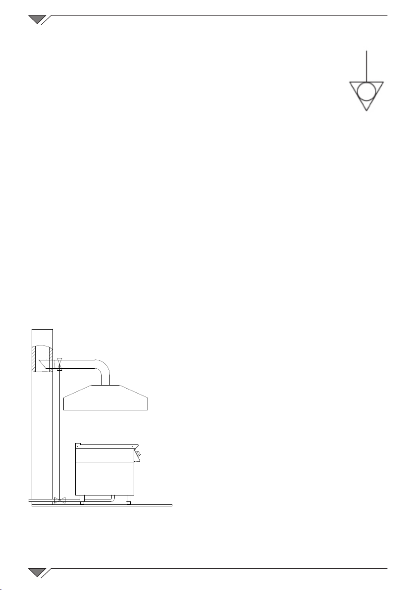
Make sure that all openings and holes designed for heat intake/discharge
are not obstructed.
Do not block the intake or heat dissipation openings and vents and
place the appliance beneath an extractor hood whose system must be
legally compliant.
100
50
Fig. 1

10
1.3 Equipotential
The appliance must be included within an equipotential
system whose eciency is checked in compliance with the
standards in force.
For connection there is a clamp, located on the frame and
marked with the symbol of Fig. 3.
If the appliance is installed in the vicinity of other household appliances,
ensure the electrical cables and pipes are suciently distanced from the
hot parts of the same.
Make sure there is sucient air circulation around the appliance.
1.4 Smoke exhaust
The machine must always be installed under a fume hood.
For proper installation, make sure that the following guidelines are
followed:
• the volume extracted must be higher
than that of the ue gases generated
(see current regulation);
• the gas supply to the appliance must
be controlled directly by this system and
must cut-o whenever the ow rate
drops below the values prescribed;
• the gas must only be re-admitted to
the appliance manually;
• the end part of the appliance
evacuation pipe must be positioned
inside the base perimeter projection of
the hood (Fig.4).
Fig. 4
Fig. 3

11
1.5 Gas connection
Check on the rating plate (Fig. 5),
placed on the side in the bottom
left corner, that the appliance has
been tested and approved for the
type of gas that the user uses.
Make sure the nozzles installed
upstream of the appliance
correspond to the type of gas that
is available.
Check the data on the technical
plate to make sure that the
pressure reducer capacity is
sucient for the appliance supply.
The appliance has been set in the
factory for use with G20 gas at a
pressure of 20 mbar, unless requested
dierently on placing the order.
Do not reduce the diameter of
the section between the reducer
and the appliance. Fit a gas lter
above the pressure adjuster in order to ensure optimum operation.
Connect the appliance to a special gas pipe with an internal diameter of
at least 16 mm for G1/2” connections and a diameter of at least 20 mm
for G3/4” connections.
The pipe may be xed or exible
and the coupling can be in metal.
Make sure that the exible metal
connection pipe to the gas tting
does not touch overheated parts
and that it cannot be twisted. Use
xing straps that comply with the
installation regulations.
Envision cocks or drain valves with
an internal diameter no smaller than
the coupling pipe mentioned above.
After connecting the pipe, make sure that the joints and couplings have
no leaks. To do this, use soapy water or specic foamy product to identify
the leaks.
NEVER USE OPEN FLAMES!
GASKET SEAL
GAS INTAKE RAMP
HOSE
Fig. 6
Fig. 5
CAT
G30
G31 G20 G25
COUNTRY
A �
TYPE
MOD
NR
II
II
II
II
II
II
I
I
I
I
2H3+
2H3B/P
2E+3+
2ELL3B/P
2H3B/P
3+
2E+
2E3+
3B/P
2E
ΣQn kW
G30 G20 G25
kg/h m³/h m³/h
Pmbar
Pmbar
Pmbar
Pmbar
Pmbar
Pmbar
Pmbar
Pmbar
Pmbar
Pmbar
28-30
28-30
28-30
28-30
30
50
30
30 30
50 50
50
37
37
37
37 20
20
20
20
20
20
20
20/ / /
/ /
/
/ / 25
/ /
20
25
/
/
/
IT - ES - IE - PT
GB - GR - CH
LT - DK - FI - EE- NO
LY - CZ - SK - SI - SE
FR
AT - CH
CY - BE
DE
BE
LU
MT - IS - HU - CY
PL
PRDISPOSTO A GAS - PREVU A GAZ
PRESET FOR GAS - EINGSTELLT AUF GAS
PREDISPUESTO A GAS - PREDISPOSTO À GÀS
mbar
V Hz kW IP EN 203-1
MADE IN ITALY
CAT
II
II
2L3B/P
2EK3B/P
m³/h
Pmbar
Pmbar
G30
G31 G20 G25
G25.3
COUNTRY
NL
NL
30 30 / 25 /
30 30 / 2520
G25.3
A

12
Control of the Nominal Heat Input:
During initial installation and during maintenance or adaptation to
another type of gas nominal heat input must be measured.
It can be measured using the volumetric method with the aid of a litre
counter or chronometer.
The appliance must be
supplied with one of the types
of gas whose properties and
pressure are set out in Tab. 1.
Checking Gas Pressure:
The supply gas pressure must be measured
at the height of the pressure outlet (Fig.7-8)
after removing the seal screws.
Use a exible pipe, connect a gauge to
the pressure point (e.g. a liquid manometer
with minimum resolution of 0.1 mbar)
and measure the inlet pressure whilst the
appliance is operating.
The pressure value must not be less than
the minimum limit indicated in Tab. 1.
If the value is not respected, switch o the appliance, disconnect the
gauge, close the seal screw and insert the washer, contact the gas
Fig. 8
GAS TYPE PRESSURE IN mbar.
NOM MIN
G20 NATURAL GAS
20 18
L.P.G. G30/31 29/37 25/25
Table 1
Fig. 7
PRESSURE
OUTLET
SCREW
GAS VALVE
(mild steel and compoundl
versions)

13
company to test main gas supply pressure. A pressure adjuster may
need to be inserted upstream of the appliance.
1.6 Transformation for use with Dierent Gas
If the appliance must be connected to a dierent type of gas than that
for which it has been prepared, the nozzles must be replaced.
Replacing the main burner nozzle:
Remove the front panel, unscrew the nozzle “G” (Fig.9) and replace
it with that corresponding to the pre-selected gas, according to that
stated on the technical plate. The nozzles are marked in hundredths of
a millimetre.
Replacing the pilot burner nozzle:
The pilot burner is accessible after the front
panel has been removed. Replace the nozzle
“D” (Fig.10), loosening the xing nut “E” and
mounting that relative to the type of gas with
which the machine is to be powered. Verify that
the ame envelops the thermocoupling and that
its appearance is correct.
Fig. 9
G
Fig.10
D
E
nozzle G

14
Primary air regulation
The primary air is properly regulated if ame stability is ensured or, in
other words, if there are no breaks in the ame with the burner cold and
if there is no backring with the burner hot.
The distance envisioned for adjustment of the primary air is indicated
in Fig.9 and in Tab.4
Unscrew the injector “G” and install the one intended for the type of
gas, checking the distance “X” for the air.
When conversion or adaptation has been completed for every type of
gas, it is MANDATORY to ax the corresponding plate above the technical
plate, which is provided along with the nozzles.
Once operations to convert the gas type have been completed, check
the seal of removed parts using the bubble test or indicated foamy
substances. NEVER USE OPEN FLAMES to check for the presence of
gas leaks.
WARNING!
THE MANUFACTURER IS NOT RESPONSIBLE AND WILL NOT
COVER UNDER GUARANTEE DAMAGE CAUSED BY INCORRECT
INSTALLATION NOT FOLLOWING THE INSTRUCTIONS.
Adjustment of the reduced ow rate (versions in mild steel and compound)
To obtain reduced ow rate, loosen the screw “F”
(Fig.11).
Make sure the gas quantity is sucient to maintain
a stable and uniform minimum and resist switching to
maximum ow - minimum ow.
F
Fig. 11

15
2. TECHNICAL SPECIFICATIONS
MODEL F.G72.. F.G74.. F.G741..
Rated output kW 7 14 14
N. tops 1 2 1
Construction type A1
Total gas consumption
G20 Natural Gas m3/h 0.74 1.48
G30 LPG Kg/h 0.55 1.10
Tab.2
MODEL F.G92.. F.G94.. F.G941..
Rated output kW 9 18 18
N. tops 121
Construction type A1
Total gas consumption
G20 Natural Gas m3/h 0.85 1.69
1.26
G30 LPG Kg/h 0.63
Tab.3
Gas
Type
Pressure
(mbar) Min/Max Pilot
Nozzle
Opening
aerator
(mm)
Bypass
Burner 7
kW
G20 20 200K 27 9.0 adjustable
G31 28-30/37 90 135K 19 9.0 ---
G31 50 80 120K 19 9.0 ---
Burner 9
kW
G20 20 235K 27 10.0 adjustable
G31 28-30/37 115 155K 19 10.0 ---
G31 50 100 135K 19 10.0 ---
Tab.4

16

17
3. GENERAL INSTRUCTIONS FOR USE
3.1 Commissioning
The appliance must be used only for the purpose for which it was
designed. Any other use is improper.
Before putting the appliance into operation, you should carefully carry
out all the necessary checks to ascertain the conformity of the equipment,
of the installation of the appliance as provided by law and according to
the technical and safety instructions given in this manual.
It is also necessary to remove all of the packing material, including the
protective lm applied on the walls of the machine.
The vents and air slots must be open and free of obstructions.
Clean the appliance of protective industrial grease residue using water
and detergent for steel parts and for the top. Then rinse and dry with a
soft, clean cloth.
Any pieces of that were removed for installation must be replaced.
Do not leave any type of container on the surface that could melt with
heat, such as plastic, aluminium, paper, card, textiles or other.
Modications or repairs to the appliance must only be carried out by
qualied personnel. To guarantee safety, only use original replacement
parts and accessories.
Unauthorised work and non-original replacement parts invalidate the
guarantee.
3.2 Functioning of models with plate in mild steel and
compound
3.2.1 Ignition
After having prepared the
appliance for functioning as
described previously, proceed
with ignition as follows:
• turn the knob and hold
it pressed in the pilot
burner ignition position
(Fig.12). At the same
time, repeatedly press
the piezoelectric ignition Fig.12
OFF positionPILOT ON position
Piezoelectric
Ignition

18
button until the pilot ame ignites. Ignition
can be observed through the peephole on
the instrument panel. Hold the knob down for
a further 15-20 seconds. If the ame should
go out when the knob is released, repeat the
operation;
• after having turned on the pilot, turn the knob
further to the left and adjust the intensity of the
ame in the MIN and MAX positions. Burners
ignition can be checked through the same
peephole used to check pilot ignition.
3.2.2 Switch-o
It is possible to switch o the main burner only by turning the knob
to the pilot ignition position .
In this way, only the pilot burner remains on.
If, instead, the knob is taken to the "O" position, the pilot burner also
switches o in addition to the main burner.
Warning! The models with plate in mild steel must NOT be used
to cook dairy products and eggs. We recommend to interpose
baking paper between the food and the plate!
3.3
Operation of models with valve (chrome-plated top)
3.3.1 Ignition
Turn on the pilot:
Open the gas valve upstream of the appliance.
Piezoelectric
Ignition
PILOT ON position OFF position
Fig.14
Knob:
O
pilot ame
large ame
small ame
Fig.13

19
Turn the temperature regulation knob and hold it pressed in the pilot
position . At the same time, repeatedly press the ignition button for
approximately 20 seconds until all air in the pipes has escaped and the
pilot turns on.
Ignition can be observed through the peephole on the instrument panel.
Hold the knob down for a further 15-20 seconds. If the ame should go
out when the knob is released, repeat the operation
Ignite the main burner:
When the pilot is ignited, proceed to ignite the main burner by turning
the temperature regulation knob to the desired degrees. Burners ignition
can be checked through the same peephole used to check pilot ignition.
3.3.2 Switch-o
It is possible to switch o the main burner only by turning the knob to
the pilot ignition position.
In this way, only the pilot burner remains on.
The main burner switches o when the temperature is reached or if it is
necessary to lower that initially set.
If the temperature regulation knob is moved to the "O" position, the
pilot burner also switches o in addition to the main burner, and the fry
top will stop working.
3.4 Emptying the drip tray
Regularly check the grease drip
tray located under the front control
panel.
Turn o the machine, empty the
tray by extracting it from the front
and take care not to burn yourself.
It can be washed in the dishwasher.
Before turning the fry top on
again, reposition the tray in its slot. Fig.15

20
4. MAINTENANCE and CLEANING
Disconnect the appliance from the gas supply before performing any
cleaning or maintenance operations.
At the end of the working day, clean the appliance, both for reasons of
hygiene and to prevent operating faults.
The appliance must never be cleaned with direct or high pressure
jets of water. Moreover, the appliance should not be cleaned with wire
sponges, ordinary steel brushes or scrapers; eventually, and only for the
steel parts, you can use stainless steel wool, wiping the appliance in the
direction of the sheet metal grain.
The top must be cleaned using
hot water and non-chlorine-based
detergents. It must never be cleaned
using steel wool, sandpaper or similar.
If dirtiness is accentuated, the use of
synthetic sponges is recommended
(e.g. Scotchbrite).
For non-stainless steel tops, it is
mandatory to dry the top and protect
it with cooking fat or oil to keep it in
excellent condition and prevent rusting.
If rust should form due to water, humidity and/or failure to protect the
top at the end of cooking, the rust must be removed to prevent corrosion
using stainless steel wool until the oxidised part has been polished. Wash,
dry and protect the top as described previously.
Make sure not to protect the top when wet or damp. In addition to being
pointless, this operation is damaging since rusting will increase under
the layer of protection!
After cleaning, rinse with clean water and dry using a cotton, wool or
linen cloth. Do not use synthetic materials.
All maintenance must be performed by qualied sta.
At least once per year, have the appliance fully checked, including an
assessment of the gas circuit seal and of the components in general.
All routine and special maintenance must be performed by qualied
personnel.
Fig.16
This manual suits for next models
12
Table of contents
Other Giorik Fryer manuals