Giotto professional User manual

1
INSTALLATION MANUAL GIOTTO SCREEN
Before installing the Giotto screen, please read the follo ing instructions carefully:
•
The Giotto screen must be used INDOORS ONLY.
•
It is forbidden to stay under the Giotto screen.
•
The Giotto screen must be installed by qualified personnel only.
The manufacturer and his agents do not take responsibility for any damage to property or personal injury if the screen
is used outside of recommended specifications or in case of incorrect/poor quality installation.
For any repairing, please contact directly the dealer you purchased the unit from.
WARRANTY
This projection screen is guaranteed 2 years from the purchase date for manufacturing defects.
Responsibility is limited to repairing or substitution of the defected components and ithout any other charge at our
expense.
Warranty is officially voided if the screen has been dismantled or it is returned ith collision damage or defective due
to incorrect installation. Repairs must be carried out by an Approved Screen International Certified Engineer.
Warranty is officially voided if:
1) the motor is removed / dismantled;
2) the screen has been transit damaged;
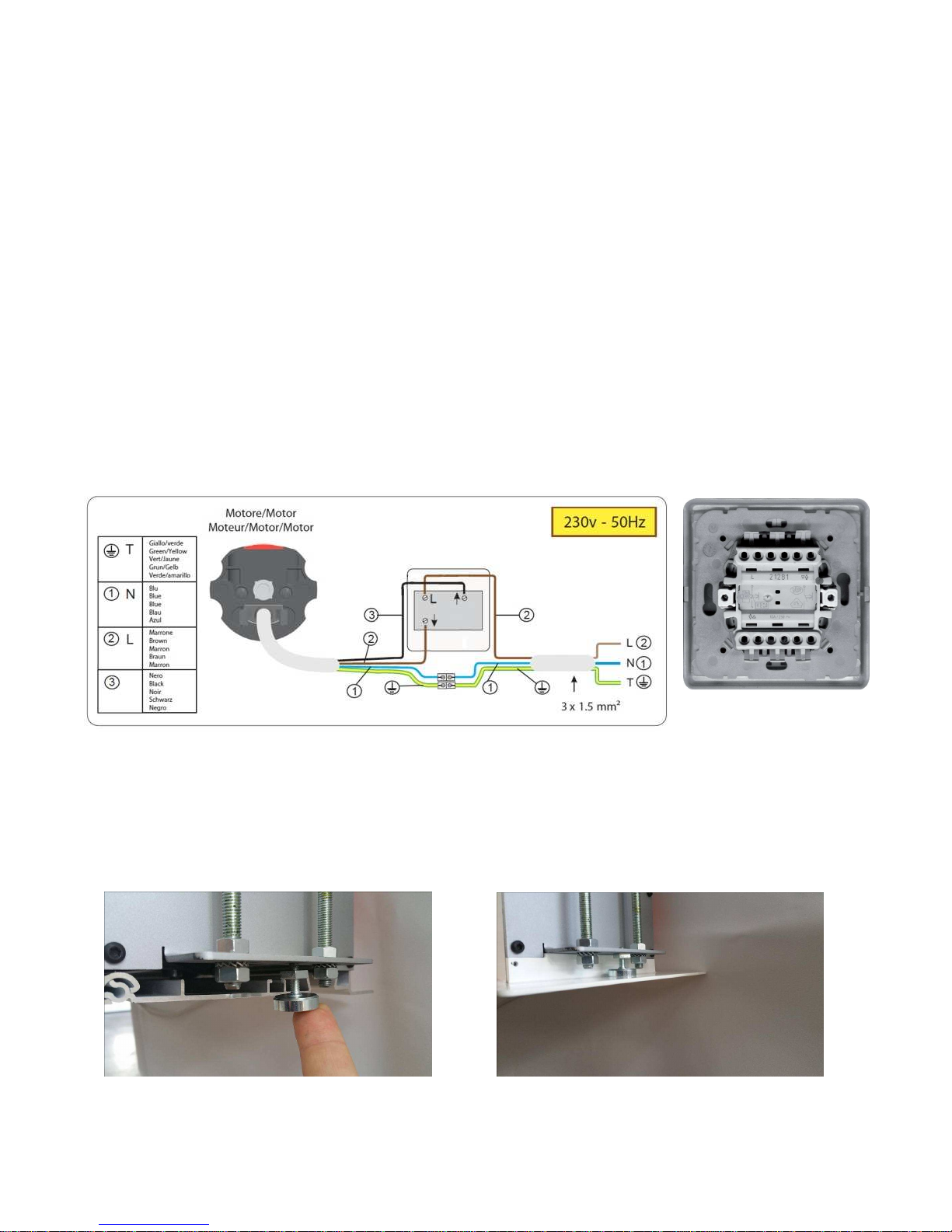
3) the instructions regarding the electrical connections have not been follo ed;
4) the products have to be installed follo ing the electric regulations (CEI) and the other local specific la s;
5) electrical accessories have been used that are incompatible ith the screen motor causing damage to its
internal components;
6) the motor end stops have been modified ithout the authorisation of the factory;
7) the sticker regarding the serial number of the product has been altered, deleted, removed or is illegible.
DO NOT install this screen nearby or over heating or air conditioning systems, because PVC is a plastic material hich
dilates and remains damaged if it is subjected to heat and/or cool air.
DO NOT install this screen either facing direct sun light or blocking a indo as PVC could be damaged and make
aves for the explanations given above.
The PVC cloth is very sensitive to temperature range.
We advise you to ait 2 hours for the screen to acclimatise before using the screen after delivery, especially if screen is
brought into a arm environment from cold.
DO NOT WASH the projection surface ith alcohol or solvent nor ith commercial cleaners. Every no and then dust
the surface ith a dry and clean duster.
Please, be very careful because any kind of stain on the PVC cloth is inerasable.
The screen has to be used sho ing the total projection sizes indicated on the packaging; therefore it is NOT allo ed to
adjust the end stops to restrict the total drop or extend it. Restricting the total drop of the screen is likely to cause your
screen surface to lose its flatness.
The manufacturer ill not accept returns of screens for repair ithout manufacturer’s authorization (RMA number) and
ithout a suitable packaging.
WARNINGS: ONCE PROJECTION IS FINISHED, ROLL UP THE SCREEN (keeping
the screen rolled do n can cause deformations to the projection surface)
When you open the packaging, please CHECK that it contains ALL the components below.
In case one or more components are missed, please re er to the dealer you purchased the
product rom.
1. Nr. 1 Giotto screen
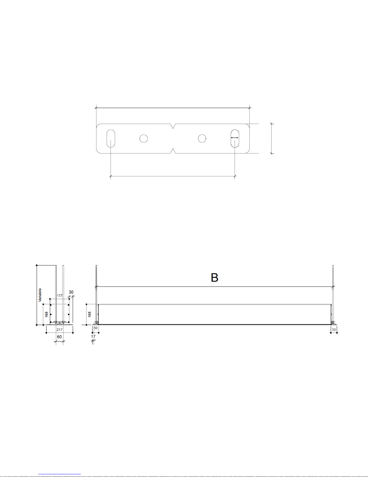
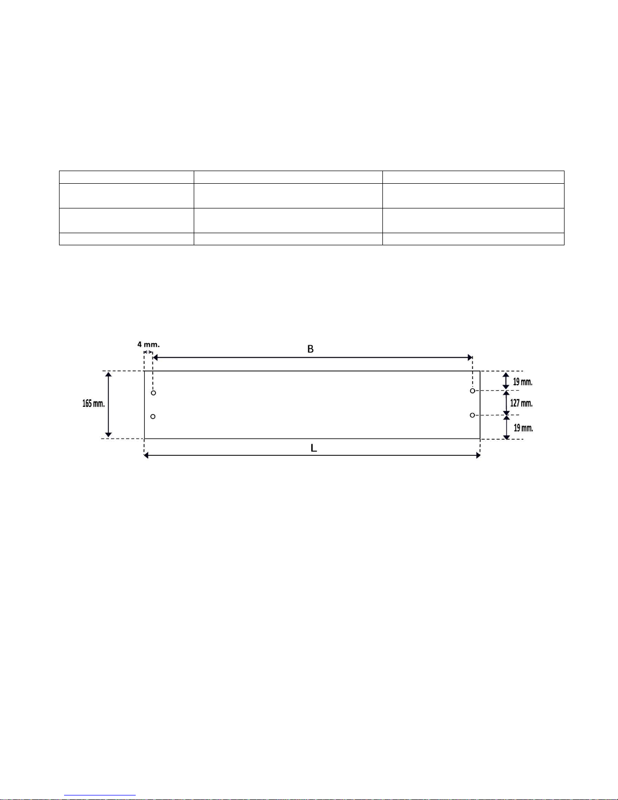
2. Nr. 2 ceiling mounting brackets
3. Nr. 4 metal threaded rods 100 cm. long x M8
3. Nr. 12 washers M8

2
4. Nr. 12 nuts M8
5. Nr. 02 magnets
6. Nr. 02 white side pro iles
7. Nr. 1 on/o switcher
8. Nr. 1 installation manual
INSTALLATION INSTRUCTIONS
In case of dirty and dusty environments, you can remove the roller tube ith
projection cloth from the housing.
-Open the trapdoor (located at the lower side o the housing) manually by pulling it
(the trapdoor is kept closed by magnets inside it) and cut the wire clamps located le t
and right rom the dowel bar. Furthermore, remove also the packaging oam parts
rom the dowel bar.
-Remove also the brackets where the magnets attach on (see central and right pictures
below) and stock them in a sa e place in order to remount them later on.
-Pull rom inside the screen housing the power cable or approx. 1 mt.
-At the right side o the roller tube where the motor is located, unscrew the two bolts
that keep the side brackets ixed (see central picture below). Release the bracket with
the roller tube and pull it toward right in order to get it out rom the screen housing.
-Release the power cable rom the motor (see right picture here below).
WARNING: Roller tube ith projection cloth has to be stocked TAKING CARE to
protect it ith a clean plastic sheet and placed it inside the carton box of the
screen. Please be careful that the carton box is clean and empty so that the
projection surface does NOT TOUCH anything that could cause permanent
marks on it.

3
In order the reinstall the roller tube with projection cloth into the screen housing, please
ollow the instructions above back links.
The Giotto screen can be installed either on a ceiling where a terwards the alse ceiling will
be built around the screen or into an existing alse ceiling.
A - GIOTTO SCREEN INSTALLATION here after ards the false ceiling ill
be built around the screen.
In order to mount the Giotto screen to the concrete ceiling please proceed as ollows:
1. A Drill two holes (suitable or wall plugs and screws NOT included in the packaging)
in the concrete ceiling at a distance o 127 mm or each ceiling bracket
(DISTANCE A – Fig. 1) whereas or the distance o the holes between each
bracket, ollow the drawing and the scheme below (DISTANCE B – Fig. 2):
TECHNICAL DRAWING CEILING MOUNTING BRACKET
A
Fig. 1
Fig. 2
9 mm
.
157 mm.
127 mm.
30 mm.

4
Example: I you bought a GIOTTO HOME CINEMA 200X125, the width o the viewing area is 200 cm., and
the distance B has to be 200 cm. + 33,5 cm. = 233,5 cm.
2. A Fix the ceiling mounting brackets onto the concrete ceiling with suitable wall plugs
and screws (NOT SUPPLIED) – re . Fig. 3
3. A Cut the metal threaded rods at the desired length, taking care that the metal rod
has to be screwed inside the ceiling bracket or 10 mm. and irmly tightened with a
washer and a M8 nut onto the ceiling bracket (Fig. 4). Li t the screen up (taking
care the label “AUDIENCE SIDE” is towards the audience) and insert the lower end
o the threaded rods inside the holes o the side plate on each side o the screen
cabinet, or 13 mm and irmly tightened the upper and lower washers and nuts M8
supplied (Fig. 5).
Now proceed at point 4.
SCREEN MODEL
DISTANCE
(B)
GIOTTO PROFESSIONAL (
no
black side
borders)
Width
o viewing area
+ 23,5 cm.
GIOTTO HOME CINEMA (
with black side
borders )
Width o viewing area
+ 33,5 cm.
GIOTTO TENSIONED
Width o viewing area
+
52,5 cm.
Fig. 5
Fig.
3
Fig. 4

5
B. GIOTTO SCREEN INSTALLATION into an existing false ceiling
In order to install a Giotto screen in an existing alse ceiling, you need to have the
possibility to access inside the alse ceiling.
1. B Cut the hole in your alse ceiling ollowing the indications in Fig. 6 (distance L) and
drill into the concrete ceiling two holes at a distance o 127 mm. in order to ix the
ceiling mounting brackets (see DISTANCE A - Fig. 1), whereas or the distance o
the holes between each bracket, ollow the drawing and the scheme below
(DISTANCE B) in Fig. 6.
SCREEN MODEL
LENGHT
OF THE HOLE
(L)
DISTANCE
(B)
GIOTTO PROFESSIONAL
(no black side borders)
Width o viewing area
+ 28,5 cm. Width o viewing area
+ 23,5 cm.
GIOTTO HOME CINEMA
(with black side borders)
Width o viewing area
+ 38,5 cm. Width o viewing area
+ 33,5 cm.
GIOTTO TENSIONED Width o viewing area
+ 57,5 cm. Width o viewing area
+ 52,5 cm.
WIDTH OF THE HOLE: 16,5 CM.
Example: I you bought a GIOTTO HOME CINEMA 200X125, the width o the viewing area is 200 cm.
and the widt o the hole L has to be 200 cm. + 38,5 cm. = 238,5 cm., whereas distance B has to be
200 cm. + 33,5 cm. = 233,5 cm.
2. B Fix the ceiling mounting brackets onto the concrete ceiling with suitable wall plugs
and screws (NOT SUPPLIED) – re . Fig. 3
3. B Cut the metal threaded rods at the desired length, taking care that the metal rod has
to be screwed inside the ceiling bracket or 10 mm. and irmly tightened with a
washer and a M8 nut onto the ceiling bracket (Fig. 4). Li t the screen up (taking care
the label “AUDIENCE SIDE” is towards the audience) and insert the lower end o the
threaded rods inside the holes o the side plate on each side o the screen cabinet,
or 13 mm and irmly tightened the upper and lower washers and nuts M8 supplied
(Fig. 5).
Now proceed at point 4.
Fig. 6

6
4. In case the roller tube with projection cloth has been removed be ore installation,
mount it again inside the screen housing ollowing, back links, the instructions at page
2.
In case the roller tube with projection cloth has NOT been removed, open the
trapdoor (located at the lower side o the housing) manually by pulling it (the trapdoor
is kept closed by magnets inside it) and cut the wire clamps located le t and right rom
the dowel bar. Furthermore, remove also the packaging oam parts rom the dowel
bar. Close the trapdoor.
5. ELECTRIC CONNECTION
Connection o the power supply must be carried out by quali ied personnel only, using
the scheme showed on the drawing below (Fig. 7). Pay attention to wires colour and
ix the switcher near the screen because the rolling up or down o the projection
sur ace should be visible to the operator!! NEVER CONNECT MORE THAN ONE
SCREEN MOTOR TO THE SAME SWITCHER. Use the supplied switcher only. IN
CASE OF MAINTENANCE, UNPLUG THE POWER SUPPLY.
In case the screen is controlled via relais, take care that the control system
is programmed so there is no tension on the relais for at least 1 sec. during
s itching bet een rolling up and rolling do n operations and viceversa.
I installation is or an non existing alse ceiling (option A), you can now build around
the Giotto screen the alse ceiling.
6. Now roll down and up the screen in order to test the complete installation.
7. Screw the magnets into the le t and right side plate o the screen housing (Fig. 8).
Fix the white side pro iles le t and right onto the magnets (Fig. 9).
WARNING: CHECK BY REMOVING THE WHITE SIDE PROFILES, EVERY 6 MONTHS
THAT SCREWS, WALL PLUGS AND BRACKETS ARE IN GOOD CONDITIONS AND WELL
TIGHTENED.
Fig. 7
Fig. 8
Fig. 9
This manual suits for next models
2
Table of contents
Popular Projection Screen manuals by other brands

Multibrackets
Multibrackets M user guide

Draper
Draper M Series Specifications

Dragonfly
Dragonfly DF-TB-XXX-ALR Series installation manual

Da-Lite
Da-Lite Presenter P-50 operating instructions

Draper
Draper Ultimate Access Series E Installation & operating instructions

SCREENLINE
SCREENLINE Maximilian 2.0 Pro manual

BRANDRUP
BRANDRUP FLYOUT 100 111 01S quick start guide

Grandview
Grandview Edge R1 Series user manual

ADEO SCREEN
ADEO SCREEN PROFESSIONAL PSCHP0001 user manual

Screen Research
Screen Research TheaterCurved Reference X-Mask T-XLR3 installation manual

LG
LG SC100 owner's manual

Kingpin
Kingpin FFS Series Operation guide