Gippsland Aeronautics GA8 Owner's manual

OWNERS AND PILOTS
INFORMATION MANUAL
(For Approved Document please refer to C01-01-04)
Model GA8
THIS GA8 OWNERS AND PILOTS INFORMATION MANUAL IS FOR REFERENCE ONLY AND
THEREFORE MUST NOT BE USED AS A SUBSTITUTE FOR THE OFFICIAL CASA
AUSTRALIA APPROVED FAA ACCEPTED FLIGHT MANUAL DOCUMENT.
Gippsland Aeronautics Pty Ltd
P.O. Box 881
Morwell Victoria 3840
Australia
Tel.: +61 3 5172 1200
Fax: +61 3 5172 1201
GA-FM-04 Owners and Pilots Information Manual Page (i)

This page intentionally left blank

GIPPSLAND AERONAUTICS
Model GA8
GA-FM-04 Owners and Pilots Information Manual Page (ii)
CONTENTS
Section
1 General
2 Limitations
3 Emergency Procedures
4 Normal Procedures
5 Performance
6 Weight and Balance/Equipment List
7 Aircraft and Systems Description
8 Aircraft Handling, Servicing and Maintenance
9 Supplements

This page intentionally left blank

GIPPSLAND AERONAUTICS SECTION 1
Model GA8 GENERAL
GA-FM-04 Owners and Pilots Information Manual Page 1-1
1 SECTION 1 SECTION 1
GENERAL
TABLE OF CONTENTS
Paragraph Page
1.1 INTR DUCTIONO .........................................................................................................1-2
1.1.1 Owners and Pilots Information Manual ..........................................................1-4
1.1.2 Definitions.......................................................................................................1-4
1.2 GENERAL DESCRIPTION..........................................................................................1-5
1.2.1 Aircraft............................................................................................................1-5
1.2.2 Engine............................................................................................................1-5
1.3 SYM OLS, ABBREVIATIONS AND TERMINOLOGYB ................................................1-6
1.3.1 General Symbols and Abbreviations..............................................................1-6
1.3.2 General Airspeed Terminology and Symbols.................................................1-8
1.3.3 Meteorological Terminology...........................................................................1-9
1.3.4 Power Terminology ........................................................................................1-9
1.3.5 Engine Controls and Instruments...................................................................1-9
1.3.6 Aircraft Performance and Flight Planning Terminology................................1-10
1.3.7 Weight and Balance Terminology ................................................................1-10
1.4 USE OF METRIC/IMPERIAL UNITS.........................................................................1-11

GIPPSLAND AERONAUTICS SECTION 1
Model GA8 GENERAL
Page 1-2 Owners and Pilots Information Manual GA-FM-04
1.1 INTRODUCTION
The Owners and Pilots Information Manual consists of an introductory section and eight
additional numbered sections. These sections provide owners and pilots with familiarisation
of the GA8 Airvan in all phases of flight, ground handling terminology and servicing.
The operating procedures presented herein are the result of Gippsland Aeronautics
knowledge and experience gained over time. For specific information in regard to this
Information Manual, please contact:
Gippsland Aeronautics Pty Ltd
P.O. Box 881
Morwell Victoria 3840
Australia
Tel.: +61 3 5172 1200
Fax: +61 3 5172 1201
Email: [email protected]

GIPPSLAND AERONAUTICS SECTION 1
Model GA8 GENERAL
GA-FM-04 Owners and Pilots Information Manual Page 1-3
FLOOR LINE
Ø84.0 [Ø2134] MAX
FIREWALL LINE
488.68 [12412]
110.0 [2794]
GROUND LINE
2.5° DIHEDRAL
164 [4166]
352.3 [8949]
90.5 [2299]
33.5 [851]
94.0 [2388]
GROUND LINE
94.0 [2388]
63.0 [1600]
153.0 [3885]
FLOOR LINE
Figure 1-1 Three View of the GA8
Note: All dimensions in inches and [millimetres] Pilot’s Operating Handbook (POH)

GIPPSLAND AERONAUTICS SECTION 1
Model GA8 GENERAL
Page 1-4 Owners and Pilots Information Manual GA-FM-04
1.1.1 Owners and Pilots Information Manual
The Owners and Pilots Information Manual provides all required details of the standard
aircraft and the procedures required to operate it in the normal category. Apart from the
listing in Section 6, no other details of any optional equipment fitted at the factory will be
found in the basic Owners and Pilots Information Manual.
1.1.2 Definitions
Definitions used in the Owners and Pilots Information Manual such as WARNING,
CAUTION, NOTE are employed in the following context:
WARNING
Operating procedures, techniques, etc. which if not followed correctly,
may result in personal injury or death.
CAUTION
Operating procedures, techniques, etc. which if not strictly observed,
may result in damage to the aircraft or to its installed equipment.
NOTE
Operating procedures, techniques, etc. which it is considered essential
to highlight.

GIPPSLAND AERONAUTICS SECTION 1
Model GA8 GENERAL
GA-FM-04 Owners and Pilots Information Manual Page 1-5
1.2 GENERAL DESCRIPTION
1.2.1 Aircraft
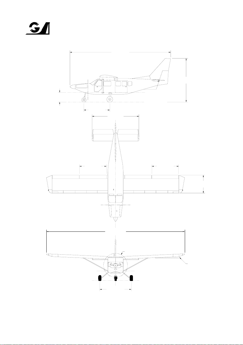
The GA8 aircraft is a strut braced, high wing, fixed tricycle undercarriage, single engine,
eight seat cabin aircraft that has been designed primarily for passenger and utility
operations.
The fuselage is an all alloy stressed skin construction and is fully corrosion protected. The
floor of the passenger cabin is provided with a quick release system to allow rapid
conversion from freight to passenger or combi configurations. The engine cowlings are
manufactured from composite materials and feature large, easily removable access panels.
The cockpit is designed to accommodate the pilot in command on the left side and all
controls, instruments, selectors and switches are located so as to be within easy reach of
the occupant of that seat. A second, optional set of flight controls and instruments may be
fitted to the right side front seat position. The centrally located control pedestal, radio stack
and overhead switch panel are accessible from either of the two cockpit seats. The cockpit
is accessed by forward hinging doors that are located on each side. The main cabin is
provided with a large sliding door on the left side at the rear of the fuselage.
The wings are of all metal stressed skin construction with full corrosion protection, and are
braced on each side by a single streamlined bracing strut. A single integral fuel tank is
located in each wing between the fuselage and the strut. The ailerons and wing flaps are of
metal construction and operate in a conventional sense.
The empennage is also an all metal stressed skin construction and is fully corrosion
protected. A variable incidence stabiliser is incorporated to provide a wide trim range with
maximum aerodynamic efficiency. The vertical surfaces feature a half span rudder that is
located on the lower portion of the fin.
1.2.2 Engine
The engine is a, six cylinder, horizontally opposed, air cooled, normally aspirated and fuel
injected Lycoming IO-540-K1A5 rated by Lycoming to 300 BHP at full throttle and 2700
RPM. Operations at 2700 RPM are limited to a maximum period of two minutes. Except for
take-off, normal full throttle operations are conducted using 2500 RPM.

GIPPSLAND AERONAUTICS SECTION 1
Model GA8 GENERAL
Page 1-6 Owners and Pilots Information Manual GA-FM-04
1.3 SYMBOLS, ABBREVIATIONS AND TERMINOLOGY
1.3.1 General Symbols and Abbreviations
AAmpere
AGL Above Ground Level
AMSL Above Mean Sea Level
AVGAS Aviation Gasoline
BHP Brake Horse Power
CASA Civil Aviation Safety Authority (Australia)
CAO Civil Aviation Order (Australia)
CAR Civil Aviation Regulation (Australia)
°CDegrees Celsius
CHT Cylinder Head Temperature
cm Centimetre, centimetres
DC Direct Current
EEast
EMERG Emergency
FAA Federal Aviation Administration (USA)
°FDegrees Fahrenheit
FAR Federal Aviation Regulation (USA)
ft Foot, feet
ft/min Feet per minute
gAcceleration due to gravity
Gal Gallon
GAMA General Aviation Manufacturers Association
hPa Hectopascal, hectopascals
HF High Frequency
ICAO International Civil Aviation Organisation
ICO Idle Cut Off
IFR Instrument Flight Rules
IMC Instrument Meteorological Conditions
in Inch, inches
in Hg Inches of mercury
in lbs Inch pounds
incr. increase
ISA International Standard Atmosphere
kg Kilogram
kg/l Kilogram per litre
kHz Kilohertz
kts, K Knots
kPa Kilopascals
kW Kilowatt, kilowatts
lLitre, litres
lb Pound, pounds
LH Left Hand
LHS Left Hand Side

GIPPSLAND AERONAUTICS SECTION 1
Model GA8 GENERAL
GA-FM-04 Owners and Pilots Information Manual Page 1-7
mMetre
m2Square metre
m3Cubic metre
mA Milli ampere
MAC Mean Aerodynamic Chord
MAN Manual
MAP Manifold Air Pressure
max Maximum
MCP Maximum Continuous Power
MHz Megahertz
mm Millimetre
min Minimum or minute
m kg Metre kilogram
NNorth
NM Nautical mile, nautical miles
OAT Outside Air Temperature
PAX Passenger
POH Pilots Operating Handbook
PPH Pounds per hour
PPM Parts per million
PROP Propeller
psi Pounds per square inch
PWR Power
QTY Quantity
qts Quarts
RH Right Hand
RHS Right Hand Side
RPM Revolutions per minute
SSouth
SAE Society of Automotive Engineers
sec Seconds
SPKR Speaker
SQ Square
SSB Single Side Band
STBY Standby
SYST System
TBO Time between overhauls
T/O Take Off
US United States (of America)
U/S Unserviceable
USA United States of America
USG US Gallon
US Gal US Gallon
VVolts
VFR Visual Flight Rules
VHF Very High Frequency
VMC Visual Meteorological Conditions
WWest

GIPPSLAND AERONAUTICS SECTION 1
Model GA8 GENERAL
Page 1-8 Owners and Pilots Information Manual GA-FM-04
1.3.2 General Airspeed Terminology and Symbols
CAS Calibrated Airspeed: the indicated speed of an aircraft corrected for position
and instrument error. Calibrated airspeed is equal to true airspeed in standard
atmosphere at sea level.
KCAS Calibrated Airspeed expressed in knots.
GS Ground Speed: the speed of an aircraft relative to the ground.
IAS Indicated Airspeed: the speed of an aircraft as shown on the airspeed
indicator. IAS values in this manual assume zero instrument error.
KIAS Indicated Airspeed expressed in knots.
TAS True Air Speed: the airspeed of an aircraft relative to the undisturbed air
through which it passes.
T.O.S.S Take-Off Safety Speed: the airspeed chosen to ensure that adequate control
will exist under all conditions, including turbulence and sudden and complete
engine failure during the climb after take-off. It is the speed required at 50 feet.
VAManoeuvring Speed: the maximum speed at which application of full available
aerodynamic control will not damage or overstress the aircraft.
VFE Maximum Flap Extended Speed: the highest speed permissible with wing flaps
in a prescribed extended position.
VNE Never Exceed Speed: the limiting airspeed that may not be exceeded at any
time.
VNO Maximum Structural Cruising Speed: the speed that should not be exceeded
except in smooth air and then only with caution.
VSStalling Speed: or the minimum steady flight speed at which the aircraft is
controllable.
VSO Stalling Speed: or the minimum steady flight speed at which the aircraft is
controllable in the landing configuration.
VXBest Angle-of-Climb Speed: the airspeed which delivers the greatest gain of
altitude in the shortest possible horizontal distance.
VYBest Rate-of-Climb Speed: the airspeed which delivers the greatest gain in
altitude in the shortest possible time.
VREF Reference Landing Approach Speed: the airspeed equal to 1.3VSO and is the
airspeed used on approach down to 50 feet above the runway when
determining landing distances.

GIPPSLAND AERONAUTICS SECTION 1
Model GA8 GENERAL
GA-FM-04 Owners and Pilots Information Manual Page 1-9
1.3.3 Meteorological Terminology
ISA International Standard Atmosphere in which:
The air is a dry perfect gas:
The temperature at sea level is 15°C (59°F):
The pressure at sea level is 1013 hPa (29.92 inches Hg):
The temperature gradient from sea level to the altitude at which the
temperature is -56.5°C (-69.7°F) is 0.00198°C (0.003566°F) per foot, and zero
above that altitude.
OAT(Outside Air Temperature) The outside free air static temperature.
Airfield Pressure Height The height registered at the surface of an aerodrome by an
altimeter with the pressure sub-scale set to 1013 hPa (29.92 inches Hg).
Pressure Altitude Altitude measured from standard sea-level pressure (1013 hPa/29.92
inches Hg) by a pressure or barometric altimeter corrected for position and instrument error.
Indicated Pressure Altitude The altitude actually read from an altimeter when the
pressure barometric sub-scale has been set to 1013 hPa (29.92 inches Hg).
Station Pressure Actual atmospheric pressure at field elevation.
QNH The local pressure setting that if set on the subscale of an altimeter will cause the
altimeter to indicate local altitude above mean sea level.
Wind The wind velocities to be used as variables on aircraft performance are to be
understood as the headwind or tail wind components of the reported winds.
1.3.4 Power Terminology
Take-Off Power Maximum power permissible for take-off.
Maximum Continuous Power Maximum power that is allowed to be used continuously
during flight.
1.3.5 Engine Controls and Instruments
Throttle Lever The lever which the pilot uses to control the engine manifold pressure.
Pitch Lever The lever which the pilot uses to control the engine RPM
Mixture Control The control that is used to vary the fuel/air ratio available to the engine.
MAP Gauge The instrument that indicates engine inlet Manifold Air Pressure
Tachometer The instrument that indicates the engine RPM.

GIPPSLAND AERONAUTICS SECTION 1
Model GA8 GENERAL
Page 1-10 Owners and Pilots Information Manual GA-FM-04
1.3.6 Aircraft Performance and Flight Planning Terminology
Climb Gradient The ratio of the change in height during a climb, to the horizontal distance
travelled.
Demonstrated Crosswind Component The crosswind component, during take-off and
landing, for which adequate control of aircraft was actually demonstrated during certification
tests.
1.3.7 Weight and Balance Terminology
Reference Datum An imaginary vertical plane from which all horizontal distances are
measured for balance purposes.
Station A location along the aircraft fuselage usually given in terms of distance from the
reference datum.
Arm The horizontal distance from the reference datum to the centre of gravity (C of G) of
an item.
Moment The product of the weight of an item multiplied by its arm.
Index Unit Moment divided by a constant. Used to simplify balance calculations by
reducing the number of digits.
Centre of Gravity (C of G) The point at which an aircraft would balance if suspended.
The distance from the C of G to the reference datum can be found by dividing the total
moment by the total weight of the aircraft.
C of G Arm The arm obtained by adding the aircraft's individual moments and dividing the
sum by the total weight.
C of G Limits The extreme centre of gravity locations within which the aircraft must be
operated at a given weight.
Useable Fuel The quantity of fuel available for flight planning purposes.
Unusable Fuel The quantity of fuel (determined under adverse fuel flow conditions) that is
not available for flight.
Empty Weight Weight of aircraft with unusable fuel and undrainable oil.
Basic Empty Weight Usually defined as empty weight plus full oil.
Useful Load Difference between take-off weight, and basic empty weight.
Maximum Take-Off Weight Maximum weight approved for take-off.
Maximum Landing Weight Maximum weight approved for the landing.

GIPPSLAND AERONAUTICS SECTION 1
Model GA8 GENERAL
GA-FM-04 Owners and Pilots Information Manual Page 1-11
1.4 USE OF METRIC/IMPERIAL UNITS
This Owners and Pilots Information Manual uses the Imperial/US unit system as the basic
system of measurement. Where common usage or available instrumentation refer to the metric
system, both units are quoted. The following conversion factors are presented as a ready
reference to the conversion factors that have been used in this manual as well as supplying
some others that may be found useful.
1 Pound (lb) = 0.4536 Kilogram (kg)
1 Pound per sq in (psi) = 6.895 Kilopascal (kPa)
1 Inch (in) = 25.4 Millimetres (mm)
1 Foot (ft) = 0.3048 Metre (m)
1 Statute mile = 1.609 Kilometres (km)
1 Nautical mile (NM) = 1.852 Kilometres (km)
1 Millibar (mb) = 1 Hectopascal (hPa)
1 Millibar (mb) = 0.1 Kilopascal (kPa)
1 Imperial gallon = 4.546 Litres (l)
1 US gallon = 3.785 Litres (l)
1 US quart = 0.946 Litre (l)
1 Cubic foot (ft3) = 28.317 Litres (l)
1 Acre = 0.4047 Hectares
1 Degree Fahrenheit (°F) = [1.8 x °C]+32
1 Inch Pound (in lb) = 0.113 Newton Metres (Nm)
1 Foot Pound (ft lb) = 1.356 Newton Metres (Nm)

GIPPSLAND AERONAUTICS SECTION 1
Model GA8 GENERAL
Page 1-12 Owners and Pilots Information Manual GA-FM-04
This page intentionally left blank

GIPPSLAND AERONAUTICS SECTION 2
Model GA8 LIMITATIONS
GA-FM-04 Owners and Pilots Information Manual Page 2-1
2 SECTION 2 SECTION 2
LIMITATIONS
TABLE OF CONTENTS
Paragraph Page
2.1 GENERAL....................................................................................................................2-2
2.2 AIRSPEED LIMITATIONS...........................................................................................2-2
2.3 AIRSPEED INDICATOR MARKINGS..........................................................................2-2
2.4 POWER PLANT LIMITATIONS...................................................................................2-3
2.4.1 Engine............................................................................................................2-3
2.4.2 Engine Limitations..........................................................................................2-3
2.4.3 Fuel Grade .....................................................................................................2-3
2.4.4 Lubricating Oil ................................................................................................2-4
2.4.5 Propeller.........................................................................................................2-5
2.5 ENGINE INSTRUMENT MARKINGS ..........................................................................2-5
2.6 WEIGHT LIMITS..........................................................................................................2-5
2.7 CENTRE OF GRAVITY LIMITS...................................................................................2-5
2.8 MANOEUVRE LIMITS.................................................................................................2-6
2.9 FLIGHT LOAD FACTOR LIMITS.................................................................................2-6
2.10 FLIGHT CREW LIMITS ...............................................................................................2-6
2.11 KINDS OF OPERATION LIMITS.................................................................................2-6
2.12 FUEL LIMITATIONS..................................................................................................2-10
2.13 MAXIMUM PASSENGER SEATING LIMITS.............................................................2-10
2.14 OTHER LIMITATIONS...............................................................................................2-10
2.15 PLACARDS ...............................................................................................................2-11

GIPPSLAND AERONAUTICS SECTION 2
Model GA8 LIMITATIONS
Page 2-2 Owners and Pilots Information Manual GA-FM-04
2.1 GENERAL
This section of the Owners and Pilots Operating Manual presents the various operating
limitations, instrument markings, colour coding, and basic placards necessary for the safe
operation of the aircraft, it's engine, standard systems and standard equipment.
All limitations contained in this section have been approved by the Australian Civil Aviation
Safety Authority, and operation in compliance with the limitations presented in this section is
required by the Federal Aviation Regulations.
For specific operations, or for operations with equipment fitted that is covered by a supplement,
any limitations applicable will be found in the relevant supplement.
2.2 AIRSPEED LIMITATIONS
The indicated airspeeds in the table below are based on airspeed calibration data from Section 5.
SPEED KCAS KIAS REMARKS
Max Manoeuvring Speed (VA)124 121 Do not make full or abrupt control
movements above this speed.
Never Exceed Speed (VNE)183 185 Do not exceed this speed in any
operation.
Max Structural Cruising Speed (VNO)145 143 Do not exceed this speed except in
smooth air and then with caution.
2.3 AIRSPEED INDICATOR MARKINGS
The airspeed indicator markings in the table below are based on airspeed calibration data from
Section 5.
MARKING IAS VALUE or RANGE SIGNIFICANCE
White Arc 57 - 97 Full Flap Operating Range. Lower limit is the maximum
weight stalling speed in the landing configuration. Upper
limit is the maximum speed with flaps fully extended.
Green Arc 64 - 143 Normal Operating Range. Lower limit is the maximum
weight stalling speed with flaps retracted. Upper limit is
the maximum structural cruising speed.
Yellow Arc 143 - 185 Operations must be conducted with caution and only in
smooth air.
Red Line 185 Maximum speed for all operations (VNE).

GIPPSLAND AERONAUTICS SECTION 2
Model GA8 LIMITATIONS
GA-FM-04 Owners and Pilots Information Manual Page 2-3
2.4 POWER PLANT LIMITATIONS
2.4.1 Engine
Manufacturer: Textron Lycoming Division
Textron Corporation
Model: Lycoming IO-540-K1A5
2.4.2 Engine Limitations
PRESSURE LIMITS (See Notes)
MAXIMUM
TEMPERATURES FUEL OIL
POWER RPM MANIFOLD
PRESSURE Cyl
Head Oil Min Max Min Max
Maximum
Take-Off
(300 BHP)
2700
(max. 2
minutes) Full Throttle 260°C
(500°F) 118°C
(245°F) 18 psi
(124 kPa)
55 psi
(379 kPa)
55 psi
(379 kPa) 95 psi
(654 kPa)
Maximum
Continuous
(275 BHP) 2500 Full Throttle
260°C
(500°F) 118°C
(245°F) 18 psi
(124 kPa) 55 psi
(379 kPa) 55 psi
(379 kPa) 95 psi
(654 kPa)
NOTE
2700 RPM may only be used for take-off to a safe height as required to clear
obstacles or reach 250ft AGL. Operations at 2700 RPM are limited to a maximum
period of two minutes. For all other operations maximum power is to be limited to
MCP at 2500 RPM.
NOTE
Other limits are as follows:
1. Minimum fuel pressure at idle:12 psi (83 kPa)
2. Minimum oil pressure at idle: 25 psi (173 kPa)
3. Maximum oil pressure at start:115 psi (793 kPa)
2.4.3 Fuel Grade
Avgas 100LL, Avgas 100/130
NOTE
For fuel tank capacities refer to section 2.12 Fuel Limitations

GIPPSLAND AERONAUTICS SECTION 2
Model GA8 LIMITATIONS
Page 2-4 Owners and Pilots Information Manual GA-FM-04
2.4.4 Lubricating Oil
1. Specification:
Textron Lycoming Specification No. 301F approves lubricating oils of any brand name
conforming to specifications MIL-L-6082 for straight mineral oil and MIL-L-22851 for ashless
dispersant oil.
Straight mineral oil must be used during the first 50 hours of operation for new and
overhauled engines, or until the oil consumption has stabilised. After the first 50 hours it is
recommended that ashless dispersant oil be used.
Refer to Lycoming Service Instruction No.1014 for further details.
2. Viscosity Grade:
The following chart is intended to assist in choosing the correct grade of oil and must be
considered as a guide only. Multiviscosity grades can also be used as indicated. Refer to
Lycoming Service Instruction No. 1014 for further details.
Average
Ambient Temperature
Mineral
Grades
Ashless Dispersant
Grades
All Temperatures
Above 27°C (80°)
Above 16°C (60°F)
-1°C (30°F) to 32°C (90°F)
-18°C (0°F) to 21°C (70°F)
Below –12°C (10°F)
-
SAE 60
SAE 50
SAE 40
SAE 30
SAE 20
SAE 15W50 or 20W50
SAE 60
SAE 40 or SAE 50
SAE 40
SAE 40, 30, 20W40
SAE 30, 20W30
Equivalence of SAE and commonly used
Commercial Grade designations:
SAE: 20 30 40 50 60
Commercial: 55 65 80 100 120
3. Capacity:
Total: 12 US quarts (11.4 litres)
Useable: 9.3 US quarts (8.8 litres)
Min safe: 2.8 US quarts (2.7 litres)
WARNING
Dipstick is calibrated in US quarts
Table of contents