Duplomatic EWM-2SS-DAD/22E-PN Installation and operation manual

89475/119 ETM
EWM-2SS-DAD/22E
Profinet Interface
Digital Card
Start - up manual
Duplomatic MS S.p.A.

Start-up Manual
89475/119 ETM
2
Duplomatic MS S.p.A. All rights reserved.
TABLE OF CONTENTS
Contacts..................................................................................................................................................... 4
Safety instructions......................................................................................................................................... 5
Characteristics ............................................................................................................................................... 6
Features..................................................................................................................................................... 6
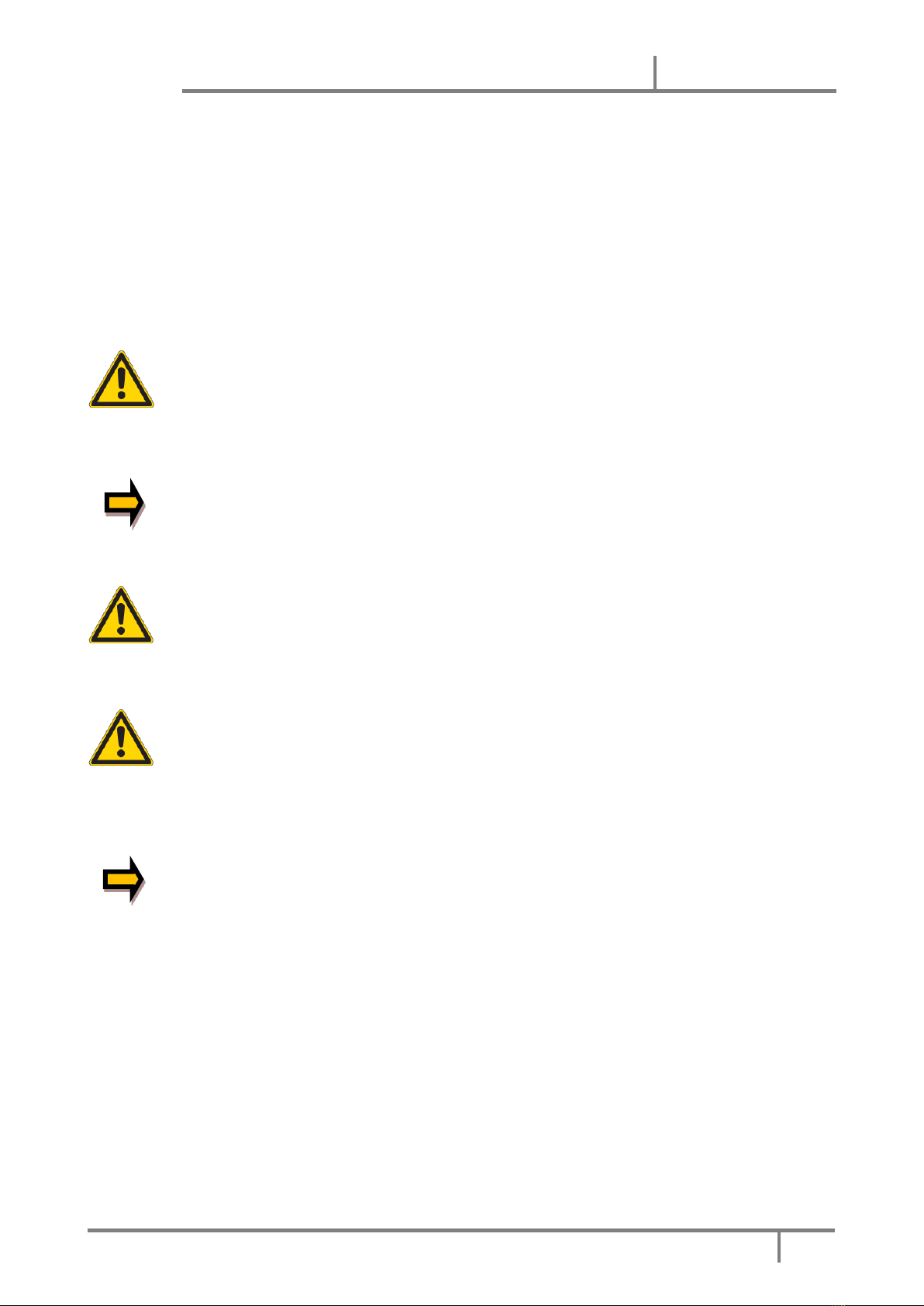
Device description ......................................................................................................................................... 7
USE AND APPLICATION...................................................................................................................................... 8
Installation instructions................................................................................................................................. 8
Typical system structure................................................................................................................................ 9
Method of operation................................................................................................................................... 10
Commissioning ............................................................................................................................................ 12
Technical description....................................................................................................................................... 13
Input and output signals.............................................................................................................................. 13
LED definitions............................................................................................................................................. 14
First section with USB.............................................................................................................................. 14
Second section (fieldbus) ........................................................................................................................ 14
Block diagram .............................................................................................................................................. 15
Typical wiring............................................................................................................................................... 16
Technical data.............................................................................................................................................. 17
Parameters OVERVIEW.................................................................................................................................... 18
Command Description..................................................................................................................................... 21
Basic parameters ......................................................................................................................................... 21
MODE (Switching between parameter groups) ...................................................................................... 21
System parameters (MODE = SYSTEM) ....................................................................................................... 21
LG (Changing the language for the help texts) ........................................................................................ 21
SENS (Malfunction monitoring) .............................................................................................................. 21
PASSFB (Password fieldbus) .................................................................................................................... 22
EOUT (Output signal: READY = OFF) ....................................................................................................... 22
HAND (Manual speed) ............................................................................................................................ 22
POSWIN (in-position monitoring range)................................................................................................. 23
VMODE (Selecting the control mode)..................................................................................................... 23
I/O parameters ............................................................................................................................................ 25
SELECT:X (sensor type) ........................................................................................................................... 25
VRAMP (ramp time for external speed demand).................................................................................... 25
SIGNAL:U (Type and polarity of the output signal) ................................................................................ 25
SYS_RANGE (axes working stroke) .......................................................................................................... 26
SIGNAL (input signal) .............................................................................................................................. 26
N_RANGE:X (nominal range of the sensor) ............................................................................................. 26
OFFSET_x:X (sensor zero correction)...................................................................................................... 26
SSI:POL (direction of the sensor signal).................................................................................................. 27
SSI:RES (signal resolution) ...................................................................................................................... 27
SSI:BITS (number of bits) ........................................................................................................................ 27
SSI:CODE (signal coding) ......................................................................................................................... 27
SSI:ERRBIT (position of the “out of range” bit)....................................................................................... 27
Positioning controller .................................................................................................................................. 28
ACCEL (acceleration in NC mode)............................................................................................................ 28
VMAX (maximum speed in NC mode) ..................................................................................................... 28
V0(loop gain setting) ............................................................................................................................... 28

EWM-2SS-DAD/22E-PN
89475/119 ETM
Duplomatic MS ▪EWM-2SS-DAD/22E-PN Start-up Manual –89475-PN/119 ETM --- Mar 2019
3
V0:RES (Scaling of the loop gain)............................................................................................................. 29
A (acceleration (ramp) time) ................................................................................................................... 29
D (deceleration / braking distance)......................................................................................................... 29
CTRL (braking characteristics) ................................................................................................................. 30
MIN (deadband compensation)............................................................................................................... 31
MAX (output scaling) ............................................................................................................................... 31
TRIGGER (Response threshold for MIN parameter)................................................................................ 31
PT1 (timing of the controller) ................................................................................................................. 32
OFFSET (correction of valve zero-offsets) .............................................................................................. 32
Synchronous controller ............................................................................................................................... 33
SYNCMODE (operation mode synchronous run).................................................................................... 33
SYNC (control parameters) ..................................................................................................................... 34
SYNCWIN (synchronization monitoring range)....................................................................................... 34
Special functions.......................................................................................................................................... 35
Drift compensation / high accurate positioning...................................................................................... 35
DC (drift compensation) ......................................................................................................................... 36
PROCESS DATA (monitoring) .................................................................................................................. 37
APPENDIX 1...................................................................................................................................................... 38
Failure monitoring ................................................................................................................................... 38
Troubleshooting ...................................................................................................................................... 38
APPENDIX 2 : PROFINET IO RT interface.......................................................................................................... 40
ProfiNet Installation guideline................................................................................................................. 40
PROFINET address assignment ................................................................................................................ 40
Device data file (.GSDML)........................................................................................................................ 41
Process data................................................................................................................................................. 41
Data sent to the device............................................................................................................................ 41
Data sent to fieldbus ............................................................................................................................... 45
Parameterizing via Fieldbus......................................................................................................................... 48
Procedure ................................................................................................................................................ 48
Parameter list .......................................................................................................................................... 49

Start-up Manual
89475/119 ETM
4
Duplomatic MS S.p.A. All rights reserved.
GENERAL INFO
This manual contains information about the digital card EWM-2SS-DAD series 22 used for
positioning or synchronization control of hydraulic axes with Profinet communication interface.
Identification code: EWM-2SS-DAD/22E-PN
by Duplomatic MS S.p.A.
Should you have any questions concerning just the card, please contact Duplomatic MS S.p.A.,
indicating the description, the code and the serial number written in the label on case side.
Other useful literature about EWM-2SS-DAD/22E-PN and its start-up can be found in:
Technical catalogue 89475-ED edition 119
Software pack EWMPC/20
For installation, start-up, commissioning and maintenance use only skilled workers and materials
fit for purpose, as recommended.
Before installation read this file and follow strictly what is indicated.
Duplomatic MS disclaims any liability for damage to person or property resulting from
noncompliance of rules and instructions here declared, from misuse or incorrect use or from
tampering of provided cards.
Contacts
Duplomatic MS S.p.A.
via Mario Re Depaolini 24
I-20015 Parabiago (MI)
ITALY
tel. number: +39 0331.895.111
fax number: +39 0331.895.249
e-mail: support@duplomatic.com
http://www.duplomatic.com

EWM-2SS-DAD/22E-PN
89475/119 ETM
Duplomatic MS ▪EWM-2SS-DAD/22E-PN Start-up Manual –89475-PN/119 ETM --- Mar 2019
5
Safety instructions
Please read this document and the safety instructions carefully. This document will help to define the
product area of application and to put it into operation. Additional documents (EWMPC/20 for the start-up
software) and knowledge of the application should be taken into account or be available.
General regulations and laws (depending on the country: e.g. accident prevention and environmental
protection) must be complied with.
These modules are designed for hydraulic applications in open or closed-loop control
circuits. Uncontrolled movements can be caused by device defects (in the hydraulic module
or the components), application errors and electrical faults. Work on the drive or the
electronics must only be carried out whilst the equipment is switched off and not under
pressure.
This handbook describes the functions and the electrical connections for this electronic
assembly. All technical documents which pertain to the system must be complied with
when commissioning.
This device may only be connected and put into operation by trained specialist staff. The
instruction manual must be read with care. The installation instructions and the
commissioning instructions must be followed. Guarantee and liability claims are invalid if
the instructions are not complied with and/or in case of incorrect installation or
inappropriate use.
CAUTION!
All electronic modules are manufactured to a high quality. Malfunctions due to the failure
of components cannot, however, be excluded. Despite extensive testing the same also
applies for the software. If these devices are deployed in safety-relevant applications,
suitable external measures must be taken to guarantee the necessary safety. The same
applies for faults which affect safety. No liability can be assumed for possible damage.
Further instructions
•The module may only be operated in compliance with the national EMC regulations. It is
the user’s responsibility to adhere to these regulations.
•The device is only intended for use in the commercial sector.
•When not in use the module must be protected from the effects of the weather,
contamination and mechanical damage.
•The module may not be used in an explosive environment.
•To ensure adequate cooling the ventilation slots must not be covered.
•The device must be disposed of in accordance with national statutory provisions.

Start-up Manual
89475/119 ETM
6
Duplomatic MS S.p.A. All rights reserved.
Characteristics
This electronic module has been developed for controlling hydraulic positioning drives.
Both axes can be controlled independently or also be driven in synchronous mode via ProfiNet.
The differential outputs are provided for the control of proportional valves with integrated or external
electronics (with differential input). Alternatively, the output can be parameterized to 4… 20 mA. This
module is intended for the connection with analogue position sensors 0...10V or 4...20mA (scalable) or
digital SSI sensor interfaces.
The internal monitoring sends information about error and operating states via the ProfiNet to the Master
controller. The operational readiness is reported via a digital output, too.
Typical applications: Positioning control or synchronization control with hydraulic axes.
Features
•Two independent positioning axes
•Can be combined for synchronized control
•Command position value parameter, actual value response, control bytes and status bytes
via fieldbus (ProfiNet IO)
•SSI-Sensor interface or analogue sensor interface (0….10V or 4…20mA)
•Simple and user-friendly sensor scaling
•Position resolution of 0.005 mm/s
•Principle of stroke-dependent deceleration for the shortest positioning time or NC profile
generator for constant speed
•Highly accurate positioning
•Advanced position control with PT1 controller, Drift compensation and Fine positioning
•Superimposed synchronization controller with PT1 (optimal for hydraulic applications)
•Optimal use with zero lapped control valves
•Synchronization control in Master/Slave or average value mode
•Fault diagnosis and extended checking function
•Simplified parameterization with EWMPC/20 software

EWM-2SS-DAD/22E-PN
89475/119 ETM
Duplomatic MS ▪EWM-2SS-DAD/22E-PN Start-up Manual –89475-PN/119 ETM --- Mar 2019
7
Device description
1
Din Rail Clip
2
USB interface
3
LED Ready, axis 1 , axis 2
4
ProfiNet Fieldbus ports
5
Communication status LED

Start-up Manual
89475/119 ETM
8
Duplomatic MS S.p.A. All rights reserved.
USE AND APPLICATION
Installation instructions
This module is designed for installation in a shielded EMC housing (control cabinet). All cables
which lead outside must be screened; complete screening is required. It is also required that no d
strong electro-magnetic interference sources are installed nearby when using our control
modules.
Typical installation location: 24 V control signal area (close to PLC)
The devices must be arranged in the control cabinet so that the power section and the signal
section are separate from each other.
Experience shows that the installation space close to the PLC (24 V area) is most suitable.
All digital and analogue inputs and outputs are fitted with filters and surge protection in the
device.
The module should be installed and wired in accordance with the documentation bearing in mind
EMC principles. If other consumers are operated with the same power supply, a star-connected
ground wiring scheme is recommended. The following points must be observed when wiring:
•The signal cables must be laid separately from power cables.
•Analogue signal cables must be shielded.
•All other cables must be screened if there are powerful interference sources (frequency
converters, power contactors) and cable lengths > 3 m. Inexpensive SMD ferrites can be used
with high-frequency radiation.
•The screening should be connected to PE (PE terminal) as close to the module as possible. The
local requirements for screening must be considered in all cases. The screening should be
connected to at both ends. Equipotential bonding must be provided where there are
differences between the connected electrical components.
•With longer lengths of cable (> 10 m), the diameters and screening measures should be
checked by specialists (e. g. for possible interference, noise sources and voltage drop).
Particular care is required with cables of over 40 m in length, the manufacturer should be
consulted if necessary.
A low-resistance connection between PE and the mounting rail should be provided. Transient
interference is transmitted from the module directly to the mounting rail and from there to the
local earth.
Power should be supplied by a regulated power supply unit (typically a PELV system complying
with IEC 364-4-4* secure low voltage). The low internal resistance of regulated power supplies
gives better interference voltage dissipation, which improves the signal quality of high-resolution
sensors in particular. Switched inductances (relays and valve coils) connected to the same power
supply must always be provided with appropriate overvoltage protection directly at the coil.

EWM-2SS-DAD/22E-PN
89475/119 ETM
Duplomatic MS ▪EWM-2SS-DAD/22E-PN Start-up Manual –89475-PN/119 ETM --- Mar 2019
9
Typical system structure
This minimal system consists of the following components:
(*1) Proportional valve with integrated electronics
(*2) Drive (e.g. hydraulic cylinder)
(*3) Position sensors
(*4) EWM-2SS-DAD/22E-PN control module
(*5) Interface to PLC with analogue and digital signals

Start-up Manual
89475/119 ETM
10
Duplomatic MS S.p.A. All rights reserved.
Method of operation
This control module supports simple point-to-point positioning with hydraulic drives. The system
works based on the principle of stroke-dependent deceleration, i.e. the control gain (deceleration
stroke) is set via parameters D:A and D:B. Alternatively it can also function in NC-Mode by setting
the loop gain parameters. In this mode the drive will move with controlled velocity to the target
position.
The deceleration characteristics can be set linearly (LIN) or approximately quadratically (SQRT1)
via the CTRL parameter. For normal proportional valves SQRT1 is the input setting.
For control valves with a linear flow curve it depends on the application. A significantly shorter
deceleration distance can often be set (D:A and D:B) for these valves if LIN is selected.
Positioning sequence:
The positioning is controlled via Fieldbus. After switching on the ENABLE input, the command
position (or target position) is set equal to the actual position of the sensor and the axis stays in
closed loop position control mode.
The READY output indicates that the system is generally ready for operation. After setting the
START-signal, the preset command value will be taken over. The axis immediately will drive to this
new command position and indicates reaching it by setting the InPos output.
The Poswin output stays active as long as the axis is within the preset Poswin window and the
START input is active. The driving velocity is regulated by a signal received by the fieldbus
interface. The axis moves with a limited speed according to this preset value.
The axis can be driven in manual mode (START is off) using the control bits HAND+ or HAND-. The
velocity is programmable. When the HAND signal is deactivated, the command position is set to
the actual position and the system stays in closed loop position control mode.
Setting the synchronous bit (GL) will synchronize both axes and the synchronization controller is
overriding the position controller of axes 2. Axes 2 is now following axes 1 according to the
master-slave-principle.
In order to achieve a reliable synchronous control, the maximum speed should be limited to about
70… 80 % of the possible speed. For compensating for deviations, the slave axis must have the
ability to move faster than the master axis. This control margin is necessary and has to be
considered during the system design.

EWM-2SS-DAD/22E-PN
89475/119 ETM
Duplomatic MS ▪EWM-2SS-DAD/22E-PN Start-up Manual –89475-PN/119 ETM --- Mar 2019
11
Influences on positioning accuracy:
The positioning accuracy is determined by the hydraulic and mechanical conditions. The right
choice of valve is therefore a decisive factor. In addition, two mutually contradictory requirements
(short position time and high accuracy) must be considered when designing the system.
The electronic limitations lie mainly in the resolution of the analogue signals, although with our
modules a resolution of < 0.01% only needs to be considered with long positions. In addition, the
linearity of the individual signal points (PLC, sensor and control module) must be considered. The
worst-case scenario is that a system-specific absolute fault occurs.
The repeat accuracy is, however, not affected by this.
V+
V+
A:A D:A
A:B
D:B
MAX:A
MAX:B
driving out
volumetric flow
P-A
and B-T
control direction
control direction
driving in

Start-up Manual
89475/119 ETM
12
Duplomatic MS S.p.A. All rights reserved.
Commissioning
Step
Task
Installation
Install the device in accordance with the circuit diagram. Ensure it is wired
correctly and that the signals are well shielded. The device must be installed in a
protective housing (control cabinet or similar).
Switching on for
the
first time
Ensure that no unwanted movement is possible in the drive (e.g. switch off the
hydraulics). Connect an ammeter and check the current consumed by the device.
If it is higher than specified there is an error in the wiring. Switch the device off
immediately and check the wiring.
Setting up
communication
Once the power input is correct the PC (notebook) should be connected to the
serial interface. Please see the EWMPC/20 program documentation for how to set
up communication.
Further commissioning and diagnosis are supported by the operating software.
Pre-
parameterization
Now set up the following parameters (with reference to the system design and
circuit diagrams):
SYSRANGE, SENSOR SETTINGS, POLARITY, ACCELERATION and DECELERATION.
Pre-parameterization is necessary to minimize the risk of uncontrolled
movements.
Parameterize specific settings for the control element (MIN for following error
compensation and MAX for maximum velocity).
Reduce the speed limitation to a value which is uncritical for the application.
Control signals
Check the control signal with a voltmeter. The control signals (PIN 15 to PIN16 and
PIN19 to PIN20) lies in the range of ± 10V. In the current state it should show 0V.
Alternatively, if current signals are used, approx. 0 mA should flow.
CAUTION! This signal depends on the EOUT setting.
Field
communication
Activate the field communication and check whether the right values and bits are
sent to the module.
Switching on the
hydraulics
The hydraulics can now be switched on. The module is not yet generating a signal.
Drives should be at a standstill or drift slightly (leave its position at a slow speed).
Activating
ENABLE
CAUTION! Drives can now leave their position and move to an end position at full
speed. Take safety measures to prevent personal injury and damage.
Drives stay in the current position (with ENABLE the actual position is accepted as
the required position). If the drive moves to an end position, the polarity is
probably wrong.
Activating START
With the start signal the demand value on the analogue demand value input is
accepted and the axis moves to the predefined target position.
If START is disabled the axis stops in the preset deceleration distance D:S.
Manual (HAND)
operation
If START is disabled the axis can be moved manually with HAND+ or HAND- .
After disabling the HAND signal, the axis stops in a controlled manner at the
current position.
Optimize
controller
Now optimize the controller parameters according to your application and your
requirements.

EWM-2SS-DAD/22E-PN
89475/119 ETM
Duplomatic MS ▪EWM-2SS-DAD/22E-PN Start-up Manual –89475-PN/119 ETM --- Mar 2019
13
TECHNICAL DESCRIPTION
Input and output signals
Connection
Supply
PIN 3, PIN 31 and
PIN 35
Power supply (see technical data)
PIN 4, PIN 32 and
PIN 36
0 V (GND) connection.
Connection
Analogue signals
PIN 11
0 V (GND), potential for analogue input signals, internally connected to PIN 4
PIN 12
0 V (GND), potential for analogue output signals, internally connected to PIN 4
PIN 13
Analogue input position actual value (X1), signal range 0… 10V or 4… 20 mA, scalable
PIN 14
Analogue input position actual value (X2), signal range 0… 10V or 4… 20 mA, scalable
PIN 15 / 16
Valve control signal axis 1.
Type of signal and polarity can be selected by the parameter SIGNAL:U1.
PIN 19 / 20
Valve control signal axis 2.
Type of signal and polarity can be selected by the parameter SIGNAL:U2.
Connection
SSI sensors
PIN 33
Power supply for sensor 1
PIN 34
0 V (GND) for sensor 1
PIN 37
CLK +
PIN 38
CLK -
PIN 39
DATA +
PIN 40
DATA -
PIN 47
Power supply for sensor 2
PIN 48
0 V (GND) for sensor 2
PIN 41
CLK +
PIN 42
CLK -
PIN 43
DATA +
PIN 44
DATA -
Connection
Digital inputs and outputs
PIN 8
Enable input: This digital input signal initializes the application. The signal will be
approved combined with the Enable of the corresponding axis.
PIN 1
READY output: when ON the module is enabled; there are no discernible errors.
When OFF Enable is deactivated or an error has been detected.

Start-up Manual
89475/119 ETM
14
Duplomatic MS S.p.A. All rights reserved.
LED definitions
First section with USB
LEDs
Description of the LED function
GREEN
Identical to the READY output.
OFF: No power supply or ENABLE is not activated
ON: System is ready for operation
Flashing: Error discovered - Only active when SENS = ON
YELLOW A
STATUS output.
OFF: The axis 1 is outside the INPOS window.
ON: The axis 1 is within the INPOS window.
YELLOW B
STATUS output.
OFF: The axis 2 is outside the INPOS window.
ON: The axis 2 is within the INPOS window.
GREEN +
YELLOW A+B
Chasing light (over all LEDs): The bootloader is active. No normal functions are
possible.
All LEDs flash shortly every 6 s: An internal data error was detected and
corrected automatically! The module still works regularly. To acknowledge the
error the module has to be cycle powered.
YELLOW A +
YELLOW B
Both yellow LEDs flash oppositely every 1 s: The nonvolatile stored parameters
are inconsistent! To acknowledge the error, the data have to be saved with the
SAVE command or the corresponding button in the WPC.
Second section (fieldbus)
LEDs
Description of the LED function
GREEN x2
besides the
jacks
Green LEDs shows link pulses. It flickers if there is network traffic
OFF: No power supply
ON: System is ready for operation
Flashing: Ethernet connection is active. Blinks if there is data transmission
GREEN on top
The green LED indicates the status of the central communication processor:
OFF: Initializing
Flashing: wait for data
Flickering: Failure
ON: Connected and active
RED on top
The red LED indicates a failure state
OFF: No Error
Flashing: Node flash test
ON: Failure in the data communication

EWM-2SS-DAD/22E-PN
89475/119 ETM
Duplomatic MS ▪EWM-2SS-DAD/22E-PN Start-up Manual –89475-PN/119 ETM --- Mar 2019
15
Block diagram
voltage: current:
15 +
12
±10 V
U1
20 -
19 +
18
±10 V
U2
19
12
18
U1
U2
4÷20 mA
4÷20 mA
GND
GND

Start-up Manual
89475/119 ETM
16
Duplomatic MS S.p.A. All rights reserved.
Typical wiring

EWM-2SS-DAD/22E-PN
89475/119 ETM
Duplomatic MS ▪EWM-2SS-DAD/22E-PN Start-up Manual –89475-PN/119 ETM --- Mar 2019
17
Technical data
Supply voltage (Ub)
Current requirement
External protection
[VDC]
[mA]
[A]
24 (±10 %)
500
1 medium time lag
Digital inputs
Input resistance
[V]
[V]
[kOhm]
OFF : < 2
ON : > 10
25
Digital outputs
Maximum output current
[V]
[V]
[mA]
OFF: < 2
ON: max. Ub
50
Analogue inputs (sensor and
demand value signal)
Signal resolution
[V]
[mA]
[%]
0… 10. 33 kOhm
4… 20. 250 Ohm
0.01 (internally 0.0031) incl. oversampling
Analogue outputs voltage
Signal resolution
Current
Signal resolution
[V]
[mA]
[%]
[mA]
[%]
2 x 0… 10; Differential output
5 (max. load)
0.024
4… 20; 390 Ohm maximum load
0.024
SSI interface
-
RS-422 specification, 150 kBaud
Controller sample time
[ms]
1
Serial interface
USB, 9600… 57600 Baud, 1 stop bit, no parity,
Echo Mode
Profinet IO : Data rate
Conformance class
[Mbit/s]
100
CC-B
Housing
Snap-on module to EN 50022
PA 6.6 polyamide
Flammability class V0 (UL94)
Weight
[kg]
0,385
Protection class
Temperature range
Storage Temperature
Humidity
[°C]
[°C]
[%]
IP20
-20… 60
-20... 70
< 95 (non-condensing)
Connections
USB-B; 11 x 4-pole terminal blocks
2 x RJ45 Ethernet jack
PE: via the DIN mounting rail
EMC
EN 61000-6-4:2007 +A1:2011
EN 61000-6-3:2005

Start-up Manual
89475/119 ETM
18
Duplomatic MS S.p.A. All rights reserved.
PARAMETERS OVERVIEW
Group
Command
Default
Unit
Description
Basic parameters
MODE
STD
-
Parameter view
System parameters (MODE = SYSTEM)
LG
EN
-
Changing language help texts
SENS
ON
-
Malfunction monitor
PASSFB
0
-
Password for fieldbus parameterization
EOUT_1
0
0,01 %
Output signal if not ready
EOUT_2
0
0,01 %
Output signal if not ready
Axis 1
HAND_1:A
HAND_1:B
3330
-3330
0,01 %
0,01 %
Output signal in manual mode
POSWIN_1:S
POSWIN_1:D
200
5000
µm
µm
Windows of the “in position” monitoring
VMODE_1
SDD
-
Method of positioning
Axis 2
HAND_2:A
HAND_2:B
3330
-3330
0,01 %
0,01 %
Output signal in manual mode
POSWIN_2:S
POSWIN_2:D
200
5000
µm
µm
Windows of the “in position” monitoring
VMODE_2
SDD
-
Method of positioning
Input and output parameters (MODE = IOCONFIG)
SELECT:X
SSI
-
Selection of the sensor signals
VRAMP_1
100
ms
Speed ramp time
VRAMP_2
100
ms
Speed ramp time
SIGNAL_1:U
U+-10
-
Type and polarity of the analogue output
SIGNAL_2:U
U+-10
-
Type and polarity of the analogue output
Axis 1
SYS_RANGE_1
100
mm
Axis working stroke
SIGNAL_1:X
U0-10
-
Type of analogue input
N_RANGE_1:X
100
mm
Sensor length
OFFSET_1:X
0
µm
Sensor offset
Axis 2
SYS_RANGE_2
100
mm
Axis working stroke
SIGNAL_2:X
U0-10
-
Type of analogue input
N_RANGE_2:X
100
mm
Sensorlength
OFFSET_2:X
0
µm
Sensor offset

EWM-2SS-DAD/22E-PN
89475/119 ETM
Duplomatic MS ▪EWM-2SS-DAD/22E-PN Start-up Manual –89475-PN/119 ETM --- Mar 2019
19
Group
Command
Default
Unit
Description
SSIconnection
SSI_1:POL
+
-
Sensorpolarity
SSI_2:POL
+
-
Sensor polarity
SSI:RES
100
10 nm
Sensor resolution
SSI:BITS
24
-
Number of transmitted bits
SSI:CODE
GRAY
-
Type of transmission code
SSI:ERRBIT
0
-
Position of the error bit
Positioning controller 1 (MODE = POS_1)
Positioning VMODE = NC
ACCEL_1
250
mm/s²
Acceleration
VMAX_1
50
mm/s
Maximum velocity
V0_1:A
10
1/s
Loop gain
V0_1:B
10
1/s
V0_1:RES
1
-
Loop gain resolution
Positioning VMODE = SDD
A_1:A
100
ms
Accelerationtime
A_1:B
100
ms
D_1:A
25
mm
Deceleration stroke
D_1:B
25
mm
D_1:S
10
mm
Controller
PT1_1
1
ms
PT1-filter time constant
CTRL_1
SQRT1
-
Control characteristic
MIN_1:A
0
0,01 %
Deadband compensation
MIN_1:B
0
0,01 %
MAX_1:A
10000
0,01 %
Output scaling
MAX_1:B
10000
0,01 %
TRIGGER_1
200
0,01 %
Deadband compensation trigger point
OFFSET_1
0
0,01 %
Offset value for the output

Start-up Manual
89475/119 ETM
20
Duplomatic MS S.p.A. All rights reserved.
Group
Command
Default
Unit
Description
Positioning controller 2 (MODE = POS_2)
Positioning VMODE = NC
ACCEL_2
250
mm/s²
Acceleration
VMAX_2
50
mm/s
Maximum velocity
V0_2:A
10
1/s
Loop gain
V0_2:B
10
1/s
V0_2:RES
1
-
Loop gain resolution
Positioning VMODE = SDD
A_2:A
100
ms
Acceleration time
A_2:B
100
ms
D_2:A
25
mm
Deceleration stroke
D_2:B
25
mm
D_2:S
10
mm
Controller commonsettings /valve adaption
PT1_2
1
ms
PT1-filtertimeconstant
CTRL_2
SQRT1
-
Controlcharacteristic
MIN_2:A
0
0,01 %
Deadband compensation
MIN_2:B
0
0,01 %
MAX_2:A
10000
0,01 %
Outputscaling
MAX_2:B
10000
0,01 %
TRIGGER_2
200
0,01 %
Deadbandcompensation trigger point
OFFSET_2
0
0,01 %
Offset value for the output
Synchronisation Controller(MODE =SYNC)
SYNCMODE
MS
-
Synchronizationmode
SYNCWIN
5000
µm
Synchronization error window
SYNC:P
25
mm
P gain (deceleration stroke, SDD)
SYNC:V0
10
s-1
Loop gain (NC)
SYNC:T1
80
ms
Timeconstant
Special functions (MODE = EXTRA)
Finepositioning / drift compensation
DC_1:AV
0
0,01 %
Point of activation
DC_1:DV
0
0,01 %
Point of deactivation
DC_1:I
2000
ms
Timeconstant of theintegratorfunction
DC_1:CR
500
0,01 %
Limit of the control range
DC_2:AV
0
0,01 %
Point of activation
DC_2:DV
0
0,01 %
Point of deactivation
DC_2:I
2000
ms
Timeconstant of the integrator function
DC_2:CR
500
0,01 %
Limit of the control range
Special commands (TERMINAL)
AINMODE
EASY
-
Input scalingmode
AIN_1:X
A: 1000
-
Free scaling of the analogue inputs (MATH). Re-
AIN_2:X
B: 1000
-
places SIGNAL, N_RANGE andOFFSET.
C:
0
X: V
0,01 %
-
Please contactW.E.St. before using these
commands.
Table of contents
Popular Industrial Electrical manuals by other brands

Murata
Murata GQM1875C2E1R1WB12 Series Reference sheet

Murata
Murata GRM1885C1H221JA01 Series Reference sheet

Siemens
Siemens 3VT9200-3MJ00 operating instructions

Murata
Murata GJM0225C1E2R5CB01 Series Reference sheet

Murata
Murata GJM1555C1H100GB01 Series Reference sheet

Murata
Murata GRM32DR60J226MA01 Series Reference sheet

Nordson
Nordson Iso-Flo HD Operator card

Murata
Murata GJM0335C1H4R8BB01 Series Reference sheet

Murata
Murata GRM155R71H821JA01 Series Reference sheet

Murata
Murata GRM155R61A475MEAA Series Reference sheet

Murata
Murata GQM22M5C2H390FB01 Series Reference sheet

Schaltbau
Schaltbau C193 Series Installation and maintenance instructions