Gira 5500 000 User manual
General safety instructions
Improper installation may result in serious
injury, e.g. from electrical shock or fire, as
well as equipment damage. Danger of
electric shock. Take account of all circuit
breakers supplying dangerous voltage to
the device or load. Comply with guidelines
and standards valid for SELV circuits for
installation and cable routing. Read these
instructions in full and observe them.
These instructions are part of the product
and must remain with the end customer.
Product features
The DCS IP data interface is an active
component for expanding a Gira door
communication system. The data interface
is used to expand the current push-button
commissioning procedure by adding
convenient commissioning via PC/laptop
and to connect the 2-wire bus to IP.
Properties
• Configuration via Gira Project Assistant
(GPA) from version 3.0.
• Commissioning of large projects.
• Reading out of the configuration data of
existing systems.
• Connection of Gira 2-wire bus to IP.
• Only suitable for indoor use.
Included in delivery
• 1 x DCS data interface
• 1 x operating instructions
• 2 x connection terminal
• 1 x cover for connection terminal
Ensure the package contents are complete
and undamaged. Please see “Warranty” in
case of any defects.
Electrical devices may only be
installed and connected by a
qualified electrician.
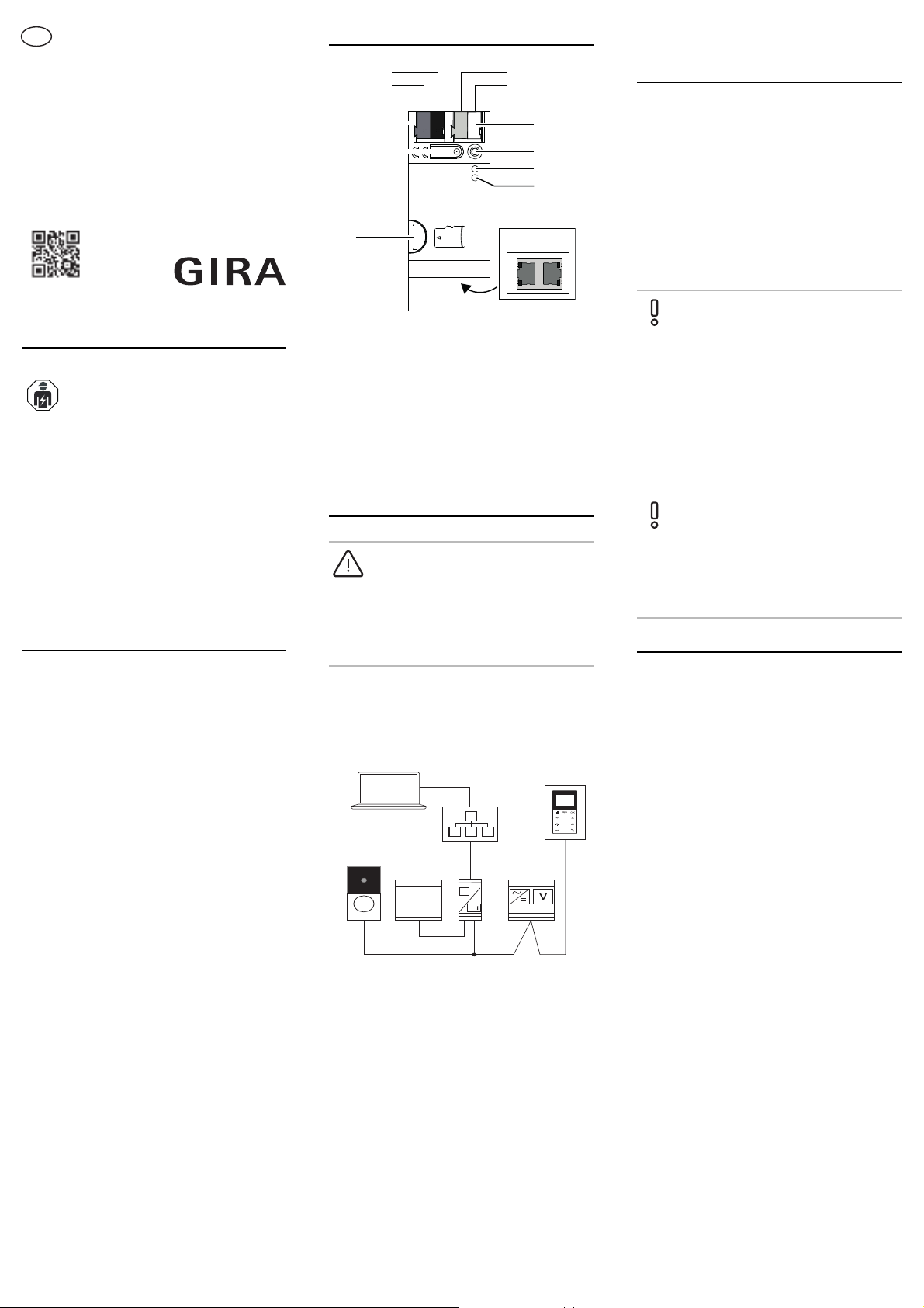
Device description
Installing the DCS IP data
interface
1. Switch the mains voltage off.
2. Place the device on the top-hat rail (TS-
35 acc. to DIN 60715). The network
connection must be located on the
bottom.
3. Connect the external power supply.
Recommendation: Use the white-yellow
connection terminal
4. Connect the Gira 2-wire bus.
Recommendation: Use the red-black
connection terminal.
5. Attach a cover cap to protect the bus
connection from dangerous voltages in
the connection area.
6. Establish the network connection.
1 Port: Additional power supply
2 Programming LED (red, reserved for future
use)
3 Function LED (green)
4 Mode/Progr.-LED (orange)
5 Port: Network (2x) incl. LEDs
6 Reserved for future use
7Programmingbutton
8 Port: Two-wire bus
DANGER
Touching live parts can result in serious
material damage or injuries, e.g. due to
fire or an electric shock.
Isolate before working on the device and
cover up live parts in the vicinity.
1
2
3
4
6
7
8
5
GPA
12V DC
2 A
IP
Data
Integrating the DCS IP data
interface into the Gira door
communication system
1. Control device: Press the "System
progr." button on the control device for 3
sec. and start the programming mode.
The LED on the control device flashes
orange.
2. DCS IP data interface: The LED Mode/
Progr. flashes orange.
3. Control device: Briefly press the
"System progr." button on the control
device and end the programming mode.
Commissioning via GPA
LEDs
Function LED (green)
Mode/Prog.-LED (orange)
Gira Project Assistant (GPA)
Configuring the DCS IP data interface via
the GPA (from version 3.0). The following
settings are made in the GPA:
• Assigning the bus address.
• Assigning call buttons and home
stations, etc.
• Begin Commissioning.
Download and install the GPA in the Gira
download area (www.gira.de/service/
download/gpa).
Quick Start Guide
In the GPA, download the Quick Start
Guide for starting up the device.
The Quick Start Guide is available at
www.gira.de/service/download or in the
online catalogue.
LED Meaning
Off IP module not working
Flashes 3 x Bus voltage failure
Flashes slowly Not configured
Steady green Normal operation
LED Meaning
Off Normal operation
On Boot loader bus coupler
active
Flashes (1 Hz) Normal operation;
Systemprog. active on
control device
Flashes
cyclically (pause
2 s + 1 pulse in
0.5 s)
Tamper protection (error
bus address control
device)
Flashes
cyclically (pause
2 s + 2 pulse in
0.5 s)
IP module is starting up
Flashes
cyclically (pause
2 s + 3 pulse in
0.5 s)
Data interface is
transferring project data
Flashes
cyclically (pause
2 s + 4 pulse in
0.5 s)
Error during transfer of
project data
10865911 30/18
DCS IP data interface
5500 000
Operating instructions
en

Network LED
Reset data interface
The DCS IP data interface can be reset to
factory default settings (factory reset) either
via the GPA or on the device itself.
Factory reset via GPA
1. Make sure that the device is switched
on.
2. Establish a connection between
computer and device (1-to-1 connection
or via the local network).
3. Start up the GPA on the computer.
4. In the GPA, open the main menu and
then open the Action Centre.
5. Click on the gear icon in the column of
the DCS IP data interface.
6. Select the "Factory reset" function: The
device is restarted and the factory reset
is carried out.
Factory reset on the device
1. Remove the terminal of the additional
power supply from the device. Make
sure that the device is de-energised.
2. Press and hold the programming button
and reconnect the power supply
terminal.
3. Press and hold the programming button
for approx. 30 sec. until the function LED
flashes slowly.
4. Within 1 sec: Release the programming
button and press and hold it again. The
function LED goes out and the Mode/
Prog.-LED flashes. The function and
Mode/Prog.-LEDs then flash alternately.
The Mode/Prog.-LED goes out and the
function LED flashes. The factory reset
was carried out. The device is no longer
configured and the password was reset.
The IP address is retained.
It is not necessary to restart the device after
the factory reset.
LED Meaning
Steady green Data transfer rate 100
Mbit/s
Flashes green Data transfer rate 10
Mbit/s
Steady orange Connection to IP
network
Technical data
Warranty
The warranty is provided in accordance with
statutory requirements via the retailer.
Please submit or send faulty devices
postage paid and with an error description
to your sales representative (retailer /
installation company / electrical contractor).
The salesperson will forward the devices to
the Gira Service Centre.
Gira
Gira
Giersiepen GmbH & Co KG
Electrical installation
systems
P.O. Box 1220
42461 Radevormwald
Phone: +49 2195 602 - 0
Fax: +49 2195 602 - 191
www.gira.de
Power supply:
2-wire bus: DC 24 V 10 %
Additional power
supply: DC 12 V to 26 V
Current consumption: max. 5 mA
Connections
2-wire bus IN: 2 x plug terminal
2-wire bus OUT: 2 x plug terminal
IP connection: 2 x RJ45
Device in general
IP communication: Ethernet 10/100
BaseT (10/
100 Mbit/s)
Ambient temperature: -5 °C to +45 °C
Storage temperature: -25 °C to +70 °C
Humidity: 93 % rel.
humidity
Protection type: IP20
Protection class: III (in accordance
with IEC 61140)
Installation width: 36 mm (2 MW)
Other Gira Recording Equipment manuals


Popular Recording Equipment manuals by other brands


Studio Logic
Studio Logic SL-760 instruction manual

JB Systems Light
JB Systems Light SE100 Operation manual

Envision
Envision Matrox Concord Installation and hardware reference manual

BOSSCO
BOSSCO DD-500 Implementation

red lion
red lion GRAPHITE G12C0000 installation guide

BOSSCO
BOSSCO BR-1600CD reference guide