Gira 1287 00 User manual

Operating Instructions
System Manual
Audio control device
1287 00


3
Table of contents
System information...................................................................................................4
Installation scenario topologies.................................................................................6
Structure of a door station ........................................................................................8
Structure of a home station ....................................................................................10
The door communication bus coupler ....................................................................12
The audio control device .........................................................................................14
Displays and operating elements of audio control device ......................................15
Connection terminals of audio control device ........................................................17
Mounting of audio control device...........................................................................18
Technical data of audio control device....................................................................18
Start-up
Switching system to programming mode ..............................................................19
One-family house: Assigning door station call button to home station..................20
House divided into several flats: Assigning door station call buttons to
home stations .........................................................................................................21
Assigning door opener............................................................................................23
Automatic door opener ...........................................................................................25
Assigning home station via floor-call button...........................................................27
Assigning several home stations to a call button....................................................28
Assigning several home stations to a floor-call button ...........................................29
Assigning call button for home station to a home station (internal call).................30
Deleting all assignments to a home station ............................................................31
Deleting assignment of the door opener ................................................................32
Replacement of defective call button top units of a flush-mounted
door station .............................................................................................................33
LED indicators on BUS devices ..............................................................................34
Acknowledgement tones of Bus devices................................................................35
Table for start-up documentation............................................................................36
Acceptance of guarantee....................................................................................... 38
4
System information
The Gira door communication system operates with the volt-
age type SELV.
With the audio control device, systems with up to 70 audio
devices can be realised in certain systems, e.g. 1 built-in
speaker with 5 add-on modules and 68 surface-mounted
hands-free feature home stations.
Depending on the system size, a maximum of 3 home stations
can be operated in parallel per call button
A call-tone differentiation is made between the following calls
at the home stations:
• door call (initiated by call button)
• floor call (initiated by floor-call button)
• internal call (initiated by call button for home stations)
Cabling and cable arrangement
Cables with a wire diameter of 0.6 or 0.8 mm can be used as
bus lines.
The following cable types are suitable for use as bus lines:
• J-Y(ST)Y (communication line)
• YR (insulated bell wiring)
• A-2Y(L)2Y (communication cable)
i
Planning software
An exact determination of the maximum system size is possi-
ble with the planning software at www.gira.de.

5
Cable lengths for audio components
The maximum total cable length (distributed among several
wiring sections) is 700 m.
A maximum of 30 devices may be connected to each wiring
section.
The maximum cable lengths of the individual sections (from
the control device to the last device) are dependent on the
cable diameter used. The guidelines for audio components
are:
• 0.6 mm diameter: 170 m,
• 0.8 mm diameter: 300 m.
6
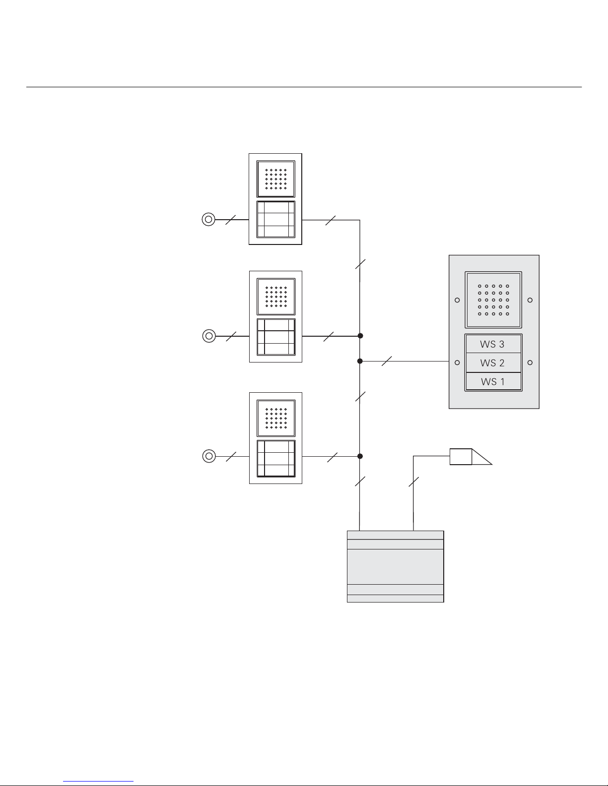
Installation scenario topologies
"Branch line" solution
Outdoor station
Control unit audio
2
2
2
Door opener
WS 3
WS 2
WS 1
2
2
2
ET
2
ET
2
ET
2
2
2
ET = Floor-call button
WS = Home station

7
"Loop-through" solution
The "loop-through" solution has the advantage of not requir-
ing the installation of a video distributor should video compo-
nents be retrofitted at a later time.
Outdoor station
Control unit audio
Door opener
WS 3
WS 2
WS 1
2
2
2
ET
2
ET
2
ET
2
2
2
ET = Floor-call button
WS = Home station

8
Structure of a flush-mounted door station
The basic structure of a flush-mounted door station is pre-
sented in the example of the flush-mounted door station with
3-gang call button.
1 Door communication bus coupler
2 Audio connection cable
3 Speech insert
4 TX_44 cover frame bottom section
(not in scope of supply)
5 Door speaker top unit
6 TX_44 cover frame top section
(not in scope of supply)
7 Call-button cover plates
8 3-gang call button
3 4 5 6
2 1 8 7

9
Structure of a surface-mounted door station
The basic structure of a surface-mounted door station is pre-
sented in the example of the surface-mounted door station
with 3-gang call button.
1 Housing, bottom section
2 3-gang call button
3 Speech cover plate
4 Cable inlet
5 Sealing ring
6 Connection terminals
7 Housing, top section
8 Call-button cover plates
1 2 3 4 5 6 7 8

10
Structure of a flush-mounted home station
The basic structure of a flush-mounted home station is pre-
sented in the example of the Comfort home station with
receiver.
1 Receiver insert
2Emptyinsert
3 Audio connection cable
4 Door communication bus coupler
5 Cover frame (not included in scope of supply)
6 Operating buttons
7 Receiver mount
8 Receiver
9 Receiver mount with cable branch
10 Receiver cable
4 5 6 7 8
3 2 1 10 9
11
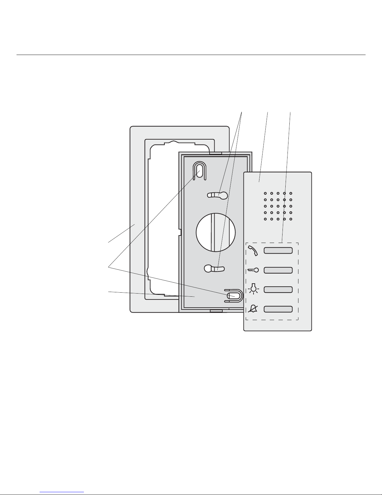
Structure of the surface-mounted hands-free feature home station
The structure of the surface-mounted hands-free feature
home station is shown in the following example.
1Mountingplate
2 Fixing holes for wall mounting
3 2-gang cover frame without crossbar
(cover frame not included in scope of supply, frameless
installation only possible with wall mounting)
4 Fixing holes for box mounting
5Housing,topsection
6 Operating buttons
3
2
1
4 5 6
12
Door communication bus coupler
The flush-mounted versions of the door and home stations are
connected to the 2-wire bus via door-communication bus cou-
plers.
The bus coupler has the following connections:
BUS
The devices are connected to the 2-wire bus via the BUS ter-
minals. Polarity need not be taken into account during connec-
tion, as the polarity of the door communication bus is neutral.
Floor-call button (ET)
With home stations, any push button (NO contact) can be con-
nected to the ET terminals as the floor-call button.
With the door stations, for example, a mechanical bell button
(NO contact) can be connected. This then acts like a call but-
ton from the Gira door communication system during start-up
and later operation.
The maximum cable length between the mechanical button
and the door-communication bus coupler is 20 m.
BUS System
Video System
ET
ZV

13
Additional supply (ZV)
The ZV terminals have two functions:
1. Power supply of call button illumination at the door
stations. The call buttons are constantly illuminated at the
door stations. If the call button illumination is to be
switched off permanently, the jumpers between the bus
and ZV terminal must be removed.
2. Additional power supply for bus devices which can no
longer be powered via the 2-wire bus.
System
The flush-mounted inserts are connected to each other with
the 6-pole audio connection cable via these connectors.
Video
The door communication bus coupler is connected to the
flush-mounted inserts of the video devices, e.g. TFT colour
display, colour camera etc., via the 2-pole connector.
i
Connecting an additional power supply
If an additional power supply is connected to the ZV termi-
nals, the jumpers must be removed.
i
Rubber plugs in the connectors
The "second" connectors are sealed with rubber plugs. These
plugs can be removed if necessary.

14
The audio control device
The audio control device is the main power supply of the Gira
door communication system.
The audio control device assumes the following tasks in the
Gira door communication system:
• provision of the bus voltage (26 V DC ± 2 V) for the door
communication system.
• power supply of call button illumination (max. 15, the
number of call button illuminations that can be supplied is
dependent on the system size and the number of home
stations operation in parallel).
• provision of door opener control, including power supply
(12 V AC, 1.6 A) of the door opener.
• power supply of a TC-gateway.
• activation of the programming mode from the entire door
communication bus system.
Additional product features of the control device:
• maximum of 70 devices, e.g.
1 built-in speaker with 5 add-on modules,
68 surface-mounted home stations.
• depending on the system size, up to 3 home stations can be
operated.
• electronic overload and short-circuit protection.
• electronic excess-temperature protection.
• overload/short-circuit LED indicator.
• LED operation indication for determination of whether or
not mains voltage is active.
• adjustable activation time of door opener.
15
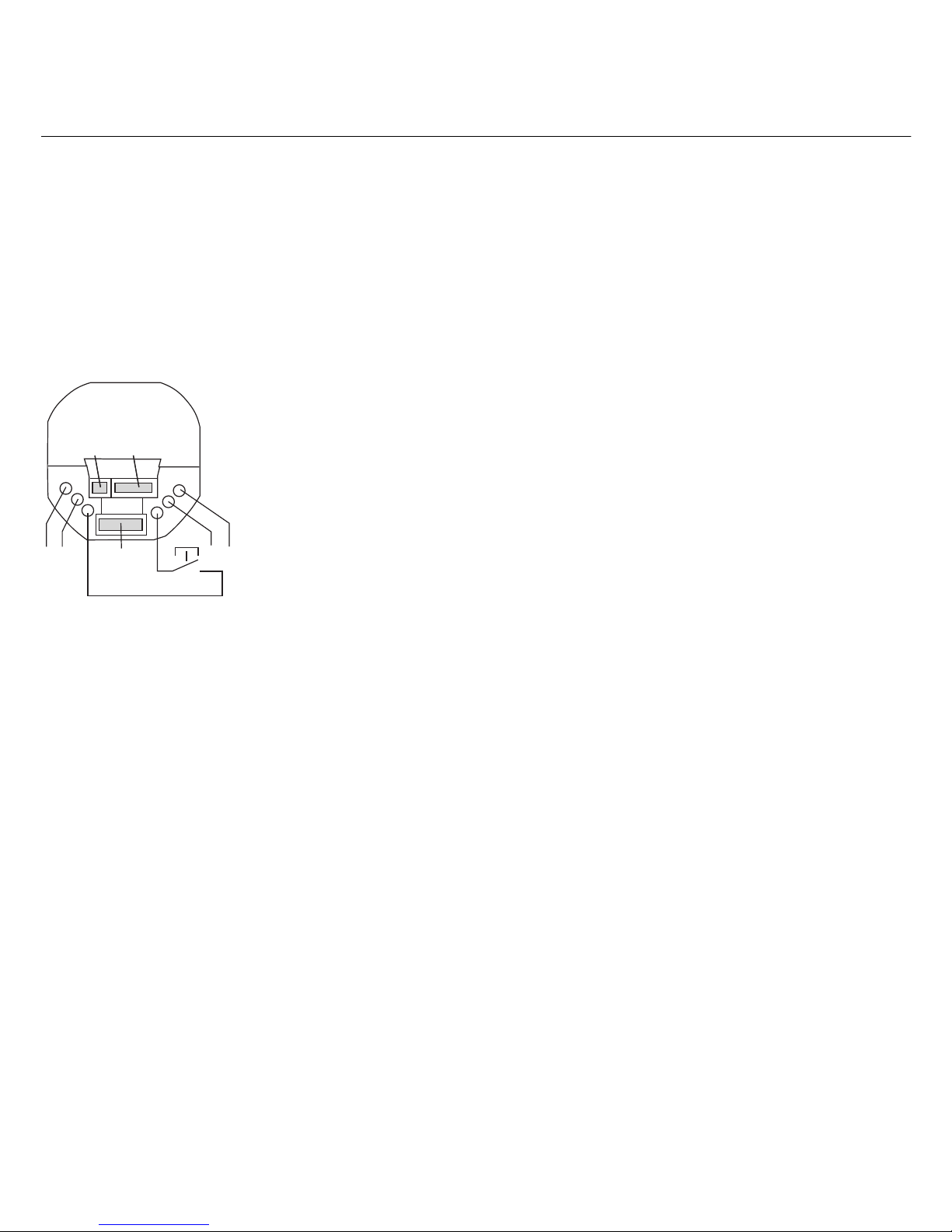
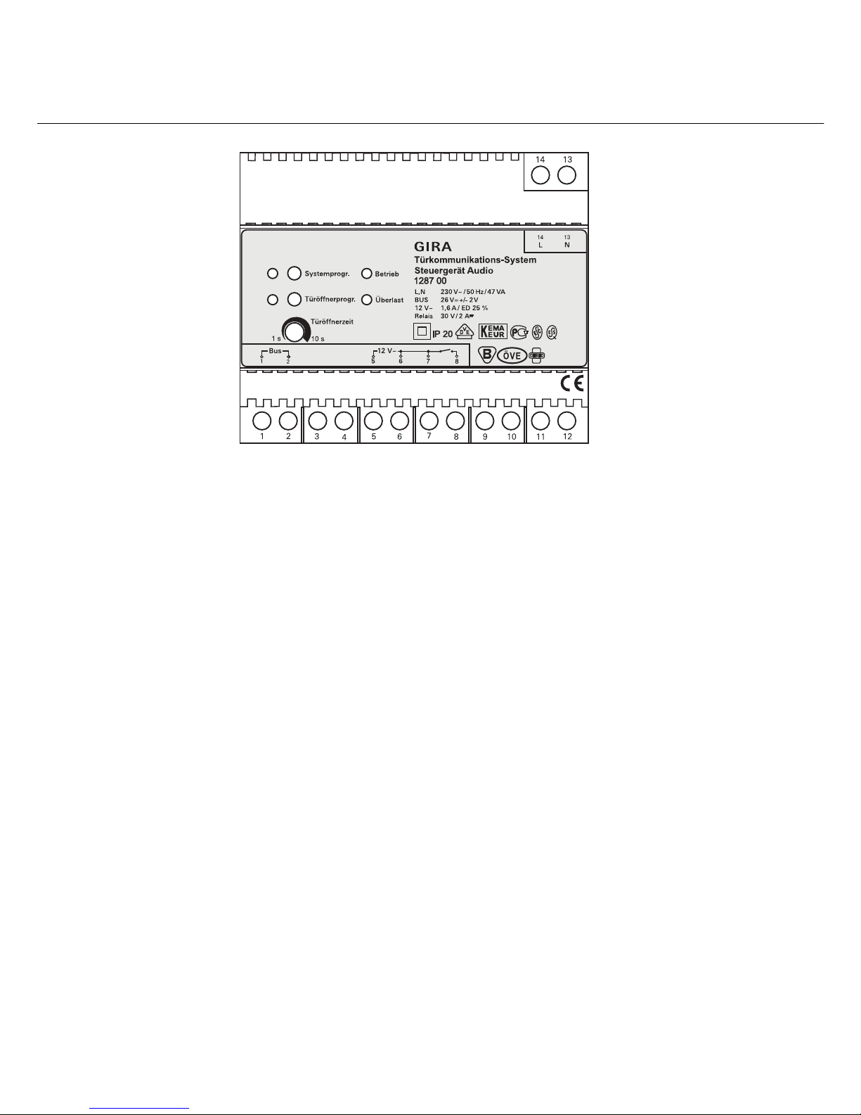
Displays and operating elements of audio control device
"Systemprog." button
By pressing the "Systemprog." button (for 3 s) the door com-
munication system is switched into the programming mode.
The yellow LED next to the programming button indicates the
active programming mode via flashing (see Page 19).
"Türöffnerprogr." button
The "Türöffnerprogr." button has two functions:
1. Activating door-opener programming mode:
If the "Türöffnerprogr." button is pressed for 3 seconds
while the system is in programming mode, the door-
opener programming mode is activated (see Page 23).
The yellow LED next to the "Türöffnerprogr." button
indicates the active door-opener programming mode via
flashing.
2. Actuation of the connected door opener.
Briefly pressing the "Türöffnerprogr." button activates the
door opener for the set time (Türöffnerzeit). The yellow
LED next to the "Türöffnerprogr." button illuminates
during the switching time.

16
"Türöffnerzeit" adjuster
The activation time of the door opener is set at the "Türöffn-
erzeit" adjuster. The setting time lies in the range 1 second to
10 seconds. The potentiometer can be adjusted with a screw-
driver with a 3 mm blade.
"Betrieb" indicator
During trouble-free normal operation, only the green "Betrieb"
LED illuminates. It indicates that the device is being supplied
with power.
"Überlast" indicator
The audio control device is equipped with an electronic over-
load protection which protects the electronics of the control
device against short-circuits and overloading on the bus line.
The overload protection is activated if, for example, the bus
line is short-circuited due to an installation error or too many
bus devices/bus loads are connected.
The red "Überlast" LED indicates both short-circuits and over-
loads. The flashing duration of the LED corresponds to the
time during which the bus voltage is deactivated when a fault
occurs. The LED then flashes for up to 20 seconds after the
fault has been eliminated.
With a permanent overload (or short-circuit), the bus voltage
is switched off for approx. 180 s after the third overload detec-
tion. During this switch-off phase, the "Systemprog.", "Türöff-
nerprogr." and "Überlast" LEDs flash.
The LEDs then flash for up to 180 seconds after the fault has
been eliminated.
17
Connection terminals of audio control device
L, N
Mains connection terminals L and N (AC 230 V, 50 Hz).
Bus
Output for powering of the Gira door communication bus with
regulated direct current (26 V DC ± 2 V, 160 mA).
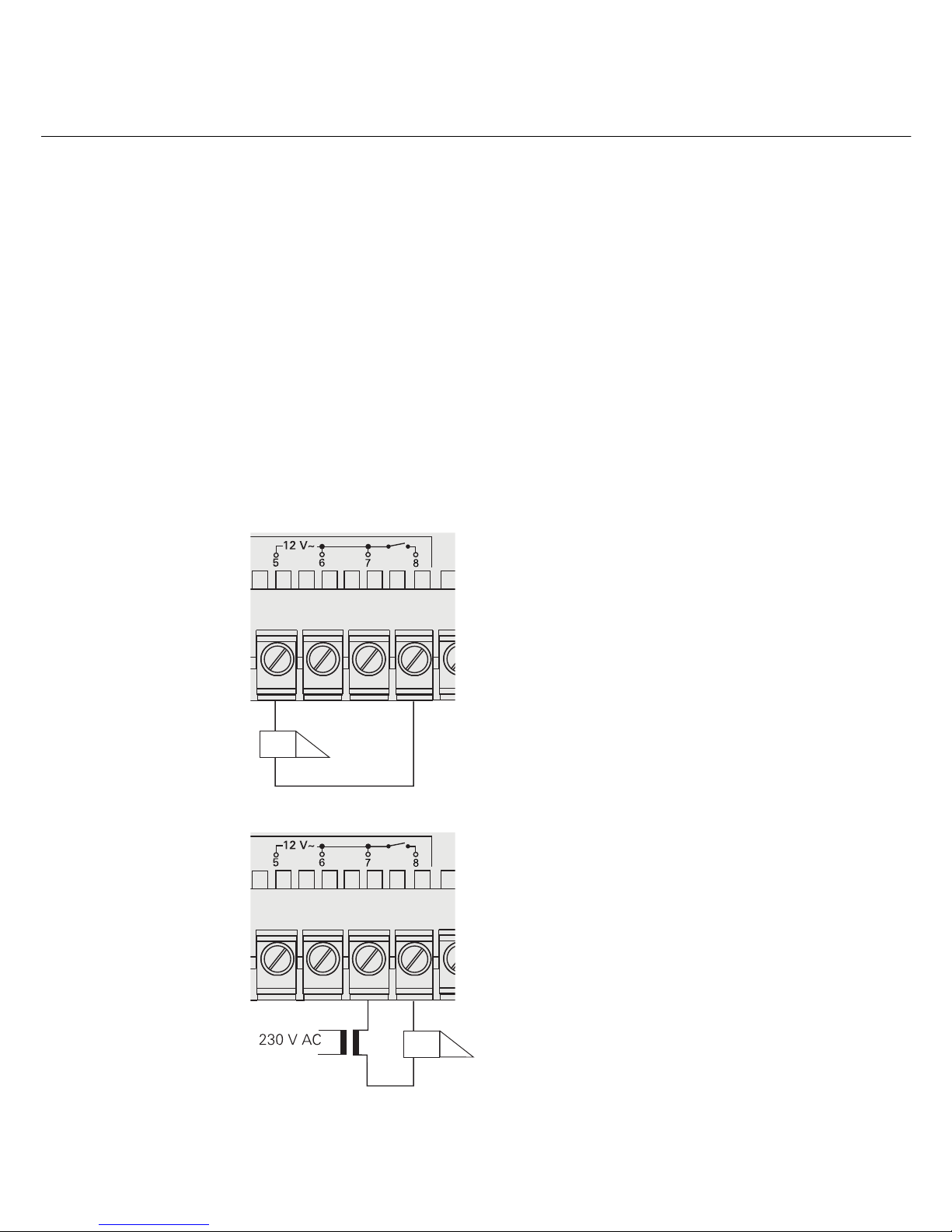
12 V AC
The 12 V AC output is used to supply power to the door opener
(power consumption of the door opener is max. 1.6 A) or the
telecommunication gateway.
Door opener relay
5678
5678
A door opener with other electrical
values (e.g. very low-ohm or 24 V)
can be connected to the relay con-
tact with an additional power supply.
Relay output for operating a door
opener (8 - 12 V AC, max. 1.6 A).
18
Mounting of audio control device
For installation protected from dripping and sprayed water,
mount the control device to a top-hat rail in the distribution.
The mains and bus connection is made via screw terminals.
The mains connection must be made via an all-pole mains
switch with at least a 3 mm contact opening.
The ventilation slits of the control device must not be blocked.
Technical data of audio control device
Primary rated voltage: AC 230 V, 50 Hz
Secondary rated voltage: SELV 26 V DC ± 2 V
Secondary rated current: 160 mA continuous load
Overload deactivation from
approx. 350 mA
550 mA peak load (max. 5 seconds)
Power: 47 VA
Protection type: IP 20
Screw terminals: 0.6 mm to 2.5 mm2
door opener output: 12 V AC, 1.6 A
Power-on time 25% (max. 10 seconds ON,
door opener: then 30 seconds OFF)
Contact load capacity
(relay output): 30 V AC, 2 A
Door opener time: adjustable, 1 to 10 seconds
Operating temperature: - 5 °C to + 45 °C
Dimensions: 6 modules, series inst. housing
Attention
Installation and mounting of electrical devices may only be
carried out by a qualified electrician.
19
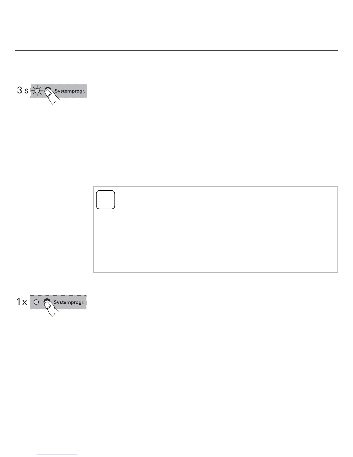
Switching system to programming mode
The Gira door communication system is switched to program-
ming mode for start-up:
1. Press the "Systemprog." button on the control device for
3 seconds.
✓The yellow LED next to the programming button flashes
(flash frequency: 1 Hz) after the button is pressed and
indicates the active programming mode.
The system is now in programming mode for approx.
7 minutes. Each time the start-up button is pressed on a door
or home station, the time is reset to approx. 7 minutes.
Exiting programming mode
1. Briefly press the "Systemprog." button on the control
device to exit the programming mode.
✓The yellow LED goes out.
Start-up documentation
For documentation on the home stations assigned to the call
buttons, please see the table on Page 36.
There you enter the names/homes in the sequence in which
you will allocate the home stations later on.
i
LED indicators on BUS devices
The active programming mode is also signalled by the LED of
various BUS devices, such as the hands-free feature home
station, the Comfort home station with receiver or the sur-
face-mounted hands-free feature home station.
An overview of the LED indication is found on Page 34.

20
One-family house: Assigning door station call button to home station
To assign a door station call button to a home station, proceed
as follows:
1. Press the "Systemprog." button on the control device for
3 seconds to start programming mode (see Page 19).
2. Press the call button on the door station for 3 seconds
until you hear a short acknowledgement tone.
✓You will hear a long acknowledgement tone.
3. Press the button on the home station for 3 seconds
until you hear a short acknowledgement tone.
✓A long acknowledgement tone indicates successful
assignment.
Three short acknowledgement tones indicate faulty
assignment. The memory of the home station may already
be occupied. A maximum of 10 call buttons can be
assigned to a home station (a maximum of 15 call buttons
to a surface-mounted hand-free feature home station).
4. Press the "Systemprog." button on the control device to
exit the programming mode.
5. Carry out a function test.
i
Releasing the button after 3 seconds
If the button press is not ended after the first acknowledge-
ment tone, all assignments of the respective door/home
station will be deleted after an additional 3 seconds.
Table of contents
Other Gira Recording Equipment manuals


