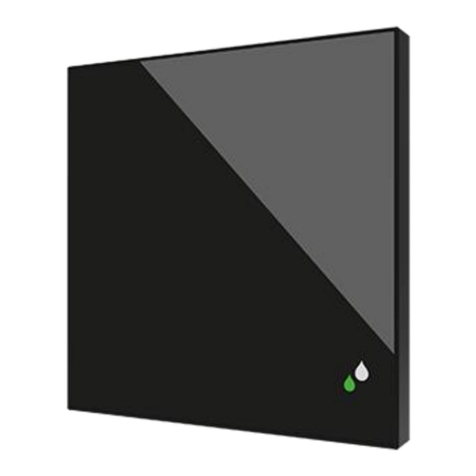
Gira KNX/EIB User manual

Push button sensor 3 Plus 2-gang F100
Order No. : 2042 xx
Push button sensor 3 Plus 3-gang (1+2) F100
Order No. : 2043 xx
Push button sensor 3 Plus 6-gang (2+4) F100
Order No. : 2046 xx
Operating instructions
1 Safety instructions
Electrical equipment may only be installed and fitted by electrically skilled persons.
Failure to observe the instructions may cause damage to the device and result in fire and
other hazards.
These instructions are an integral part of the product, and must remain with the end
customer.
2 Device components
Figure 1
(1) Operating rocker
(2) Status LED
(3) Inscription panel
(4) Operation LED
3 Function
System information
This device is a product of the KNX system and complies with the KNX directives. Detailed
technical knowledge obtained in KNX training courses is a prerequisite to proper
understanding.
The function of this device depends upon the software. Detailed information on loadable
software and attainable functionality as well as the software itself can be obtained from the
manufacturer´s product database. Planning, installation and commissioning of the device are
carried out with the aid of KNX-certified software. The latest versions of product database and
the technical descriptions are available on our website.
1/7
32575712 26.07.2013
Push button sensor 3 Plus F100
10860212
KNX/EIB

Intended use
- Operation of loads, e.g. light on/off, dimming, blinds up/down, brightness values,
temperatures, calling up and saving light scenes, etc.
- Measurement and feedback control of the room temperature
- Installation on bus coupling unit 3 in appliance box to DIN 49073
Product characteristics
- The pushbutton functions switching, dimming, controlling blinds, valuators, calling up
moods, etc.
- Three-colour status LED per control surface, which can be switched together or separately
per rocker switch according to the equipment and programming
- Indication of values and texts
- Integrated room temperature sensor
- Room temperature control with setpoint value specification
- Integrated heating timer
- Display of room and setpoint temperature
- Display of outdoor temperature – with external sensor, e.g. weather station
- Operating LED as orientation light
4 Operation
Operating a function or load
Depending on the programming, a control rocker can have up to three functions assigned to it –
left, right, entire surface. Operation depends on the specific function.
o Switch: Short press on button.
o Dim: Long press on the button. The dimming process ends when the button is released.
o Move Venetian blind: Long press on button.
o Stop or adjust Venetian blind: Short press on button.
o Call up light scene: Short press on button.
o Save light scene: Long press on button.
o Set value, e.g. brightness or temperature setpoint: Short press on button.
Display symbols and operating modes
The device compares the current room temperature with the setpoint temperature and controls
heating or cooling devices according to the current demand. The setpoint temperature depends
on the current operating mode and can be changed by the user, depending on the
programming. The operating modes and the current controller status are shown in the display.
0 Operating mode Comfort
1 Operating mode Standby
2 Operating mode Night
± Operating mode Frost/heat protection
y Comfort extension
z Room temperature setpoint manually shifted
6 Dew point. Controller disabled
x Controller operation disabled.
q Pushbutton sensor disabled.
a Fan controller with fan level display Auto/Man.: Automatic or manual fan control.
4 Heating mode
¾ Cooling mode
Ø Heating timer is active
! Warning message
The function of the display buttons is visible in the display in each case.
>, OK Apply setting, jump to following menu
×, ? Abort, exit menu
32575712 10860212 26.07.2013 2/7
KNX/EIB
Push button sensor 3 Plus F100

n, o Move up/down in the list
<, > Move to the left/right in the list
+, – Increase/reduce setting
i The display changes for individual operation steps. The system returns to the basic display
automatically after approx. 15 seconds after the last operation or when any other button is
pressed.
Changing the room temperature
For short-term manual modification of the setpoint temperature.
o Press button to the right or left next to the display.
o Acknowledge display "setpoint" with >.
o Increase or reduce the setpoint temperature with – or +.
o Depending on the programming: Accept setting with OK.
The z icon in the display shows that the setpoint temperature was adjusted.
With appropriate programming, manual changes to the setpoint temperature are cancelled
by changing the operating mode.
Settings menu.
In the "Settings" menu, the following menu items are available in sequence. Some items are not
visible, depending on the programming of the device.
- Fan controller
- Switch-over of the operating mode
- Setting setpoint temperatures
- Setting the heating timer
- Deleting the heating timer
- Set display contrast
Opening and operating the Settings menu
Figure 2
o Press both buttons next to the display simultaneously (Figure 2).
o Confirm display "Settings" with >.
The "Settings" menu is displayed.
o Select desired menu item with n or o and confirm with OK.
Heating timer: set switching time
The heating timer selects the operating mode of the room thermostat independently of the day
of the week and time – and thus the setpoint temperature of the room. A total of 28 program
slots are available for switching times.
o Open menu "Settings", select "Set heating timer" and press OK.
The display shows the first program slot.
o Select program slot with n/o and press OK.
o Set hours and press OK.
o Set minutes and press OK.
32575712 10860212 26.07.2013 3/7
KNX/EIB
Push button sensor 3 Plus F100

o Select week Mon...Son, Mon...Fri, weekend Sat...Son or an individual weekday and press
OK.
o Select operating mode for the switching time and press OK.
For the next 15 seconds the display summarises the settings for the selected program slot.
o Confirm with OK.
i After 15 seconds elapse – or when any other button is pressed – the setting procedure is
aborted without saving.
Heating timer: deleting the switching time
o Open menu "Settings", select "Delete heating timer" and press OK.
The display shows the first program slot.
o Select the program slot to be deleted with n/o and press OK.
o If you really want to delete the program slot, then press > once again.
o If you do not want to to delete the program slot, then press × or any other button, or wait
for approx. 15 seconds.
5 Information for electrically skilled persons
5.1 Fitting and electrical connection
DANGER!
Electrical shock on contact with live parts in the installation environment.
Electrical shocks can be fatal.
Before working on the device, disconnect the power supply and cover up live
parts in the working environment.
Mounting and connecting the device
Figure 3
(5) Bus coupler 3
(6) Frame
(7) Push button sensor
(8) Locking screws
(9) ESD protection mat
(10) Rocker support
32575712 10860212 26.07.2013 4/7
KNX/EIB
Push button sensor 3 Plus F100

(11) Inscription panel
(12) Rocker cover
Figure 4
(13) Anchor
(14) Fastening screws
The bus coupler 3 is connected to the bus and mounted in an appliance box.
i Use only bus coupler 3 – without a programming button. It is not possible to combine it with
other bus couplers.
Mount the double-height push button sensors on two appliance boxes with a second support
ring (see chapter 6.2. Accessories). For mounting on an appliance box, use the enclosed screw/
anchor set.
o Carefully remove the rocker support (10) and the rocker covers (12) from the push button
sensor (7).
o Attach the frame (6) to the bus coupler (5).
o Carefully attach the push button sensor (7) to the bus coupler (5).
o Screw the push button sensor to the support ring of the bus coupler module. To do this,
use the locking screws (8) provided.
o Screw the double-height push button sensors to the lower support ring or the anchors (13).
Use the screws (14) provided.
o If possible load the physical address into the device before final mounting (see chapter 5.2.
Commissioning).
o If necessary, label the inscription signs (11).
o Lock the rocker support (10), inscription signs (11) and rocker covers (12) onto the push
button sensor.
32575712 10860212 26.07.2013 5/7
KNX/EIB
Push button sensor 3 Plus F100

5.2 Commissioning
Loading the physical address and application software
Figure 5
(15) Programming LED
(16) Programming button
The programming button and LED are located under the rocker covers (Figure 5).
The rocker cover (12) and rocker support (10) over the programming button are dismantled.
i If the device does not receive any application software, or the wrong application software,
then the operation LED (4) flashes.
o Press the programming button (16).
The programming LED (15) lights up.
o Assign physical address.
The programming LED goes out.
o Load the application software into the device.
o Mount the rocker support (10), inscription panel (11) and rocker cover (12).
6 Appendix
6.1 Technical data
KNX medium TP 1
Commissioning mode S-mode
Rated voltage DC 21 ... 32 V SELV (Via bus coupler 3)
Power consumption max. 420 mW (Via bus coupler 3)
Connection mode 10 pole male connector strip
Protection class III
Ambient temperature -5 ... +45 °C
Storage/transport temperature -20 ... +70 °C
6.2 Accessories
Bus coupler 3 Order No. 2008 00
Bus coupler 3 external sensor Order No. 2009 00
Remote sensor Order No. 1493 00
Second support ring Order No. 1127 00
Inscription sheet (21x) Order No. 2872 ..
Inscription sheet (48x) Order No. 2874 ..
32575712 10860212 26.07.2013 6/7
KNX/EIB
Push button sensor 3 Plus F100

6.3 Warranty
The warranty is provided in accordance with statutory requirements via the specialist trade.
Please submit or send faulty devices postage paid together with an error description to your
responsible salesperson (specialist trade/installation company/electrical specialist trade). They
will forward the devices to the Gira Service Center.
Gira
Giersiepen GmbH & Co. KG
Elektro-Installations-
Systeme
Industriegebiet Mermbach
Dahlienstraße
42477 Radevormwald
Postfach 12 20
42461 Radevormwald
Deutschland
Tel +49(0)21 95 - 602-0
Fax +49(0)21 95 - 602-191
www.gira.de
32575712 10860212 26.07.2013 7/7
KNX/EIB
Push button sensor 3 Plus F100
Other manuals for KNX/EIB
2
Table of contents
Other Gira Temperature Controllers manuals

Gira
Gira 2104 User manual

Gira
Gira 2370 User manual
Gira
Gira System 3000 User manual
Gira
Gira Room Temperature Controller User manual
Gira
Gira 0389 Series User manual
Gira
Gira 397 User manual
Gira
Gira G1 User manual
Gira
Gira 391 User manual
Gira
Gira temperature controller User manual
Gira
Gira 396 User manual
