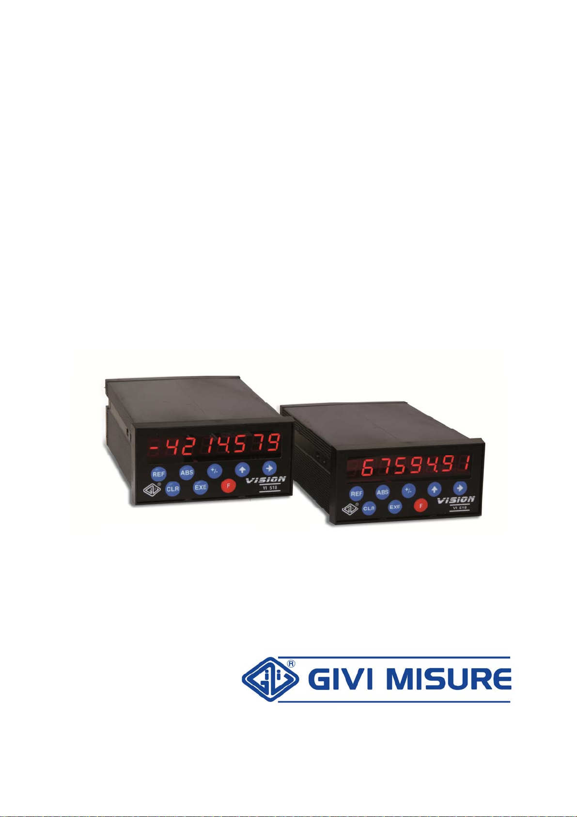
USER MANUAL DIGITAL READOUT VISION 518
MT02_A31_B_VI518_GIVI_ENG rev. A Pag. 9/32
STANDARD FUNCTIONS
To recall a function, press the F key, use the +/- key to select the code of the desired
function and confirm it with EXE.
At any time, it is possible to quit the operation by pressing the CLR key.
INCREMENTAL ENCODER INPUT
The scale zero reference (REF) can be considered as a precision micro-contact, generally
located in the middle of the measuring length. Its position, with reference to the
geometrical trim of the machine, is unchangeable over time. This could be modified only if
the scale is disassembled (e.g. due to service, maintenance or substitution). In this case,
the operator will have to set the references again.
The zero reference can be searched automatically whenever the instrument is turned on,
or manually:
A) Automatically. Whenever a momentary or prolonged interruption of power
supply (voluntary or not) occurs, the instrument proposes to the operator the
zero reference (REF) search to avoid the displaying of incorrect positions
(LAST POSITION). This is the case, for instance, of a sudden power failure
while the carriage is moving (since it would continue to move due to inertia),
or of the movement due to thermal expansion (for example caused by a
temperature drop during the night), or of involuntary or accidental shiftings
(while cleaning the machine). The operator is therefore warned against a
potential risk. He can decide to perform the zero reference (REF) search, by
passing the carriage on the corresponding points, or he can cancel the
operation, pressing the CLR key. If the scale does not have the zero
reference, press the CLR key. In this case, it is advisable to check the
accuracy of the positions reached.
B) Manually. Whenever the operator deems it necessary, he can verify the
position reached by the carriage, performing the zero reference (REF) search
manually on the axis.
SELECTING A STANDARD FUNCTION
SCALE ZERO REFERENCE (REF)