Fagor VNP400 User manual

FAGOR AUTOMATION, S. Coop. Ltda. reserves the right to modify the
contentsofthismanualwithoutpreviousnotification.

INDEX
1. CONFIGURATIONOFTHEDROMODELVNP400
1.1 Structure of the VNP400 1
1.2 Dimensions and installation 3
1.3 Front Panel 4
1.4 Rear Panel 6
1.4.1 Connectors and connections 7
1.4.1.1 Connectors X1, X2, X3, X4 7
1.4.1.2 Connector X5 8
2. MACHINEANDPOWERCONNECTION
2.1 Power connection 1
2.2 Machine interface 2
2.2.1 General considerations 2
2.3 Set-up 4
2.3.1 General considerations 4
2.3.2 Connection 4
2.4 Reference systems 5
2.4.1 Absolute and incremental coordinates 5
2.5 Start-up 6
2.6 Homesearch 11
2.7 Zerooffsets 13
2.8 Coordinate preset 14
2.9 Tool compensation 16
2.10 Troubleshooting 18
3. MACHINEPARAMETERS
3.1 Introduction 1
3.2 Operation with machine parameters 2
3.3 Setting machine parameters 4
3.3.1 Generalparameters 4
3.3.2 Parameters for the axes 7
3.3.3 Parameter Reset 14

4. DROMODEOFOPERATION
4.1 Special mill model functions 3
4.1.1 Part centering 4
4.1.2 DrillIng in a linear pattern 6
4.1.3 Drilling in circle (bolt hole pattern) 8
4.2 Special lathe model functions 10
4.2.1 Cone calculation 11
4.2.2 RPM calculation 13
4.3 Tool compensation 15
4.3.1 Tool table 16
4.3.2 Deletion of the tool table 17
4.4 Calculator function 18
4.5 Clock function 20
5. PROGRAMEDITING
5.1 Introduction 1
5.2 Program editing 2
5.2.1 Block editing 4
5.2.2 Contents of a block 6
5.3 TEACH-INprogramming 8
6. PROGRAMEXECUTION
6.1 Introduction 1
6.2 Operation 2
7. PERIPHERALCOMMUNICATIONS
7.1 Receive and send programs 2
7.2 Receive and send the tool table 4
7.3 Receive and send machine parameters 6
7.4 Probing 9
APPENDICES
ATechnical characteristics of the VNP400 2
BRecommended probe connection diagrams 4
CMachine parameter summary 5
DMachine parameter setting chart 7
EPossible power-up errors 12

Chapter: 1 Section: Page
CONFIGURATIONOFTHEDROMODELVNP400 1
1. CONFIGURATIONOFTHEDROMODELVNP400
1.1 STRUCTURE OF THE VNP400
TheFAGORVNP400DROisanenclosedandcompactmodulehavingonitsfrontpanel:
*A CRT monitor used to display the required system information.
*AkeyboardtocommunicatewiththeDROin order torequestinformationbymeans
of commands or alter the status of the DRO by generating new instructions.
The rear panel contains all the connectors necessary for machine and power interface.
Front panel of the VNP400
STRUCTUREOFTHEVNP400

Page Chapter: 1 Section:
CONFIGURATIONOFTHEDROMODELVNP400
2
Rear panel of the VNP400
STRUCTUREOFTHEVNP400

Chapter: 1 Section: Page
CONFIGURATIONOFTHEDROMODELVNP400 3
334
310
323
63,5
63,5
185
53
53228
334
192
8
184
13
M5
0 20
1.2 DIMENSIONS AND INSTALLATION
ThisDROisatable-topmodelanditshouldbeinstalledsotheoperator’seyesarealigned
with the DRO monitor.
Ithas fourlegs screwedon tothe bottomwith a5mm insidethread inorder tobe fastened
to a supporting plate or base.
FAGORAUTOMATIONoffersandoptionalDROsupportingbracketespeciallydesigned
for the VNP 400 DRO.
Dimensionsinmillimeters
DIMENSIONS

Page Chapter: 1 Section:
CONFIGURATIONOFTHEDROMODELVNP400
4
X1.500
Y-29303.2150
DEGREF1 TOOL02ABS MM
X -12.2530 Y 2.5150
Z0.2150 W 135.9470°
Z 1234.567
W -22.000
2
RESET
X
RESET
Y
RESET
Z
RESET
W
ABS/INC
1.3 FRONT PANEL
Thispanelmaybeconsideredtobedividedintotwofunctionallydifferentareas:TheCRT
monitor and the keyboard.
The monitor is divided into two display areas or windows:
1.- Main window.
Dependingontheselectedoperatingmode,thiswindowwilldisplayallthenecessary
information.
2.- This display area shows the different options which can be selected by means of
softkeys F1 thru F5.
ThekeyboardareawhichallowscommunicationswiththeDROconsistsofthefollowing
keys:
Numeric keyboardwith the 0, 1, 2, 3, 4, 5, 6, 7, 8, 9, . and ± keys. To enter signed Or
unsignedinteger and decimal values.
To access the help system from any operating mode.
When the help information takes more than one page, the symbol will
appear at the top of the screen and at the bottom indicating that these
keys must be pressed to view the previous or next page respectively.
Also the keys may be used to scroll the text up or down line by line.
1
FRONTPANEL

Chapter: 1 Section: Page
CONFIGURATIONOFTHEDROMODELVNP400 5
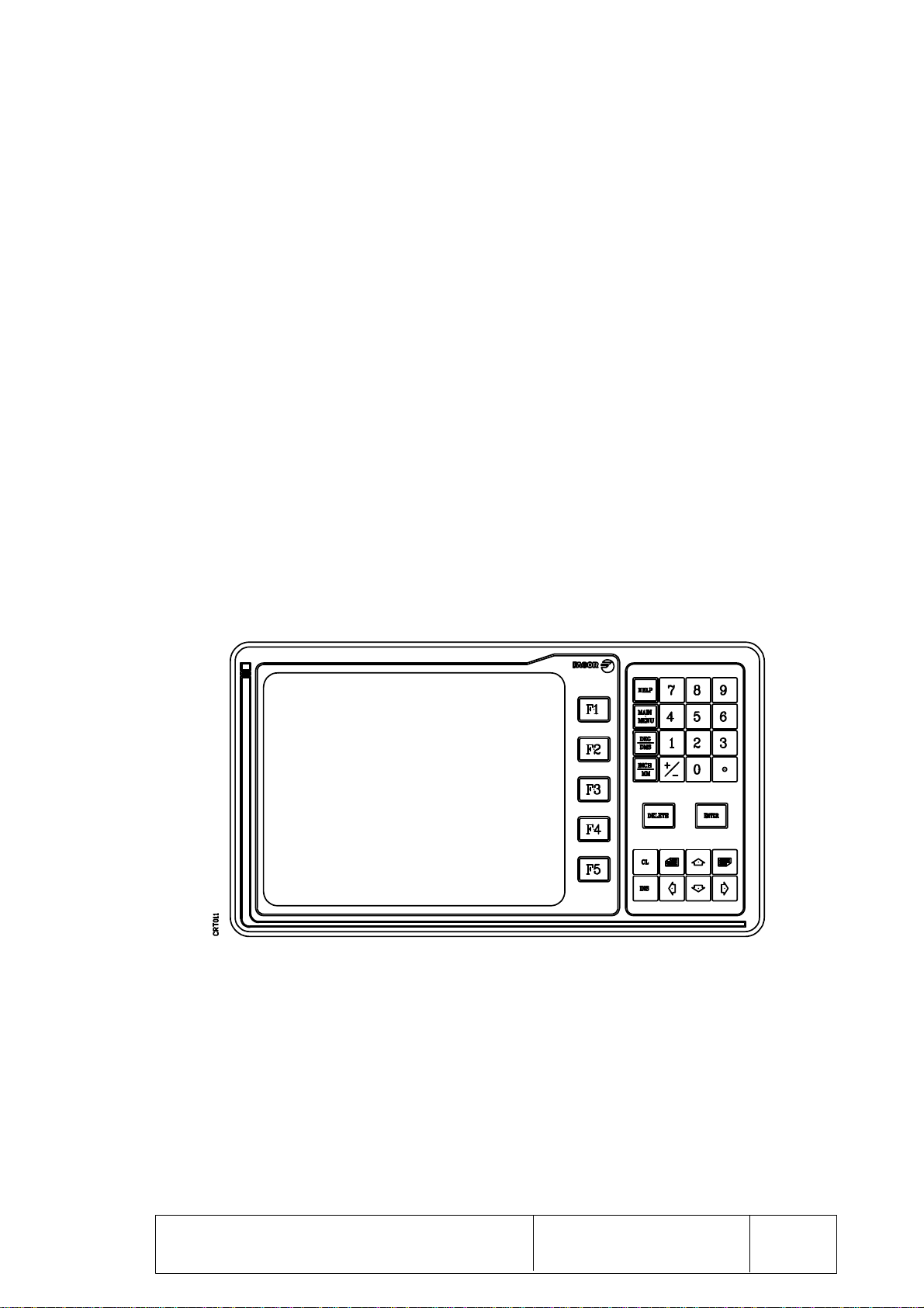
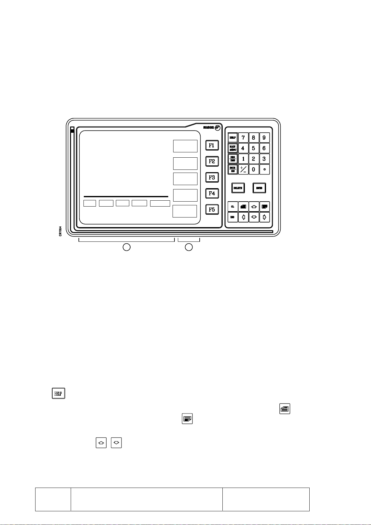
FRONTPANEL
Press again to exit from the help mode.
To access the main menu anytime.
Toggles the display of the work units of the rotary axes.
DEG Displays the positions in 0.0001 degree units. ie: 129.3900°
DMS Displays the positions in degrees, minutes and seconds. i.e: 120° 23' 24'’
Toggles the display of the work units of the linear axes.
Cancels the last character sequence entered.
Used to validate commands and data previously altered or generated.
Cancelsthe last character entered.
It is used to enter a position value directly when in TEACH-IN mode and when
assigningvaluestospecifictables.
To access the previous option, function or table.
To access the next option, function or table.
When pressing one of these keys and depending on the selected
operatingmode,theDROwilldisplaythepreviousornextfield,option,parameter
or block being edited.
SOFT-KEYS or function keys to select the different options shown on the screen.

Page Chapter: 1 Section:
CONFIGURATIONOFTHEDROMODELVNP400
6
1.4 REAR PANEL
The rear panel of the DRO consists of the following elements:
X1, X2, X3 and X4 9-pin male SAP type connectors for axis feedback connections.
One axis per connector admitting either square or sine wave signals.
X5 9-pin female SUB-D type connector for the RS 232C and probe connection.
1.- Lithium battery for memory back up when the DRO power is off.
2.- Identification label of the VNP400.
3.- Two3.15A/250VfusesforA.C.powerprotection(oneperphase).theiridentification
label is located on the fuse lid.
4.- A.C. power on/off switch.
5.- A.C. power connector for A.C. and ground connection.
6.- Brightnesspotentiometer for theCRTmonitor.
7.- Metric6mm groundterminal forgeneralmachine grounding.
REARPANEL

Chapter: 1 Section: Page
CONFIGURATIONOFTHEDROMODELVNP400 7
CONNECTORSAND
CONNECTIONS
1.4.1 CONNECTORS AND CONNECTIONS
1.4.1.1 CONNECTORS X1, X2, X3, X4
They are 9-pin male SAP type connectors for axis feedback connections. One axis per
connector admitting either square or sine wave signals.
Thetypeofcableusedmustbeshielded,therestofthecharacteristicsaswellastheirlengths
will depend on the type of feedback device being used.
Itisrecommendedtoinstallthefeedback cablesasfarawayas possiblefromthemachine
power cables.
PIN SIGNAL FUNCTION
1
2
3
+5V
0V
-5V Power to feedback devices
4
5A
BFeedback signals
6Io Machine reference Zero marker pulse (Home)
7Chassis Shield

Page Chapter: 1 Section:
CONFIGURATIONOFTHEDROMODELVNP400
8
1.4.1.2 CONNECTOR X5
It is a 9-pin female SUB-D type connector for the RS 232C and probe connection.
Thecableshieldmustbeconnectedtopin1oftheconnectorattheDROendandtothemetal
housing at the peripheral end.
SUGGESTIONS FOR THE RS 232C INTERFACE
* Connecting and disconnecting a peripheral
The DRO must be turned off when connecting or disconnecting any peripheral
through connector X5 (RS 232C serial port interface).
* Cable length
The EIA RS232C standard specifies that the cable capacitance must not exceed
2500pF.Therefore,sincetheusualcableshaveacapacitancebetween130and170pF/
meter, the maximum cable length must not exceed 15 meters (50 feet).
Itisrecommendedtouseshieldedtwisted-paircablesinordertominimizeinterference
which could cause poor quality communications through long cables.
7-conductor cables are also recommended with a section of 0.14mm2and overall
shield.
* Ground connection
All control and data signals should be referenced to the same ground cable (pin 7 -
GND-)thus avoidingvariouspoints withdifferentvoltages sinceatthe endsof long
cables some voltage level differences may occur.
PIN SIGNAL FUNCTION
1
2
3
4
5
6
7
8
9
CHASSIS
TxD
RxD
RTS
CTS
DSR
GND
DTR
Shield
Transmit data (output)
Receive data (input)
Ready to send (output)
Clear to send (input)
Data send ready (output)
Ground 0V
Probe connection
Data terminal ready (input)
CONNECTORSAND
CONNECTIONS

Chapter: 1 Section: Page
CONFIGURATIONOFTHEDROMODELVNP400 9
RECOMMENDED CONNECTIONS FOR THE RS 232C INTERFACE
* Complete connection
HOUSING
1FG
2TxD
3RxD
4RTS
5CTS
6DSR
20 DTR
7GND
FG 1
TxD 2
RxD 3
RTS 4
CTS 5
DSR 6
DTR 9 GND
7
PERIPHERAL
CONNECTORSAND
CONNECTIONS
DRO
PROBE 8

Page Chapter: 1 Section:
CONFIGURATIONOFTHEDROMODELVNP40010
FG 1
TxD 2
RxD 3
RTS 4
CTS 5
DSR 6
DTR 9 GND
7
DRO
FG 1
TxD 2
RxD 3
RTS 4
CTS 5
DSR 6
DTR 9 GND
7
*Simplifiedconnection
Used when the peripheral or computer meets one of the following requirements:
If it does not have RTS signal.
If the unit receiving data can receive it at the selected baudrate.
Nevertheless,thetechnicalmanualsofthecomputerorperipheralshouldbeconsulted
foranypossiblediscrepancies.
Whenusinganyofthesesimplifiedconnections,thecommunicationsbaudratemust
not be greater than 1200 Baud. Parameter P009.
CONNECTORSAND
CONNECTIONS
HOUSING
1FG
2RxD
3TxD
8CTS
6DSR
4DTR
5GND
1FG
2TxD
3RxD
5CTS
6DSR
20 DTR
7GND
COMPUTER PC/XT
DRO
HOUSING
COMPUTER PC/AT

Chapter: 2 Section: Page
1
MACHINEANDPOWERCONNECTION
2. MACHINE AND POWER CONNECTION
The DRO should be installed away from damaging elements such as coolants, chemical
products, blows, etc. whenever possible.
It is recommended to keep the DRO away from any device generating a strong
magneticfield which could cause undesirableimage fluctuationson themonitor.
2.1 POWER CONNECTION
TheFAGORDROmodelVNP400hasontherearpanelathree-prongconnectorforpower
and ground connection.
It can be connected to an A.C. voltage between 100V and 240V (+10% and -15%).
POWERCONNECTION

Page Chapter: 2 Section:
MACHINEANDPOWERCONNECTION2
2.2 MACHINE INTERFACE
2.2.1 GENERAL CONSIDERATIONS
Themachine-toolmusthaveallitsinterferencegeneratingelementsdecoupled(relaycoils,
contactors,motors,etc).
*D.C. Relay coils
Diode type 1N4000.
*A.C. Relay coils
RC connected as close as possible to the coils. Approximate values:
R 220 Ohm/1W
C 0,2 µF/600V
*A.C. Motors
RC connected between phases. Approximate values:
R 300 Ohms/6W
C 0,47µF/600V
Groundconnection.
A proper ground connection in an electrical installation is essential in order to achieve:
*The protection of people against electrical discharges caused by any malfunction.
*Theprotectionofelectronicequipmentagainstinterferencegeneratedatthemachine
itselforbyotherelectronicequipmentnearbywhichcouldcauseerraticmalfunctioning
ofthe equipment.
Thus,allmetallic partsmustbe connectedto thesamepoint andthis, inturn,to ground.It
is essential to establish one or two main points in the installation where the elements
mentioned above will be connected.
Cables with sufficient section must be used in order to obtain an impedance as low as
possibleandaneffectiveinterferencesuppressionmaintainingallinstallationcomponents
at the same voltage level with respect to ground.
MACHINEINTERFACE

Chapter: 2 Section: Page
3
MACHINEANDPOWERCONNECTION
VNP400 PERIPHERALS
RS232C
PROBE
X1 X2 X3 X4
AXES
X5
X5
Besides the proper grounding of the installation, the signal cables must be shielded and
twisted-pairsfor greater necessaryprotection. Theshield mustbe connectedto a specific
pointavoidinggroundloopswhichcouldcauseundesirableeffects.Thisgroundingofthe
shield is done at the DRO’s ground terminal.
Eachelementofthemachine-tool/DROinstallationmustbeconnectedtogroundthrough
the established main ground points. They will be conveniently set at a point close to the
machine-tool itself and properly connected to the Main Ground Point.
Whena second groundpoint isrequired, itis recommended tojoin bothpoints bya cable
with a section of 8mm2or greater (or two 4mm2).
Itmustbeverifiedthattheresistancemeasuredbetweeneachconnectorhousingandground
is less than 1 Ohm.
MACHINEINTERFACE

Page Chapter: 2 Section:
MACHINEANDPOWERCONNECTION4
2.3 SET-UP
2.3.1 GENERAL CONSIDERATIONS
Verifythat aproper locationfor thefeedback deviceshas beenselectedwithout blocking
the access to the various machine controls.
Verifythatthealignmentandadjustmentofthedifferentpartsoftheencodersand/orlinear
scalesarewithinthetolerancesindicatedintheirinstallationinstructions.
When installing linear scales, (transducers) it is recommended that their sealing lips be
orientedawayfromdamagingelementssuchascoolant,chemicalproducts,blows,etc.and
protecting against them with covers if necessary in order to avoid sending wrong signals
to the DRO.
Itisrecommendedtocheckthegroundconnectionwhentheelectricalcabinetisdisconnected
from the A.C. power.
ThisconnectionmustbedoneonasinglemachinepointcalledMainGroundPointtowhich
allothergroundpointsfromthemachineandfromtheelectricalcabinetwillbeconnected.
Verify that the 24V power supply at the electrical cabinet used for the digital inputs and
outputs of the DRO is REGULATED and that its 0V are connected to the main ground
point.
Checktheconnections ofthe feedbackcables totheDRO.They mustnot beconnectedto
the DRO when under power.
Before powering the electrical cabinet, look for short-circuits at all pins of all connectors
for feedback, inputs, outputs, RS 232 C (if available), etc.
2.3.2 CONNECTION
Verify that the A.C. voltage is correct.
Being the DRO off, supply power to the electrical cabinet verifying its correct response.
Power the electrical cabinet OFF and connect the axes feedback connectors to the DRO .
Power up the electrical cabinet and the DRO.
SET-UP

Chapter: 2 Section: Page
5
MACHINEANDPOWERCONNECTION
2.4 REFERENCE SYSTEMS
ThemachinewheretheVNP400DROwillbeusedmusthavethefollowingreferenceand
datum points defined for each axis:
*MachineZeroPointorhome.Itisestablishedbythemanufactureroroperatorasthe
originofthe machine’scoordinate system.
*Part Zero or absolute zero point (datum points). The part’s measurements are
displayed with respect to this point when working with absolute coordinates.
ThisDROcanstoreupto9partzerosbeingpossibletorecallandusethemanytime.
*Incremental (Floating) Zero Point. The part’s measurements are displayed with
respect to this point when working with incremental coordinates.
ItispossibletoassociateanincrementalZeropointtoeachoneofthe9absolutezeros
set previously plus another one for the Machine Reference Zero (home).
OncethedesiredPartZerosandFloatingzeroshavebeenset,theDROwillstoreinmemory
theirpositions with respect to home(in pairs).
Whenanewhomesearch iscarriedout, theDROassumes that pointas the newhome and
it recovers the absolute and incremental zeros corresponding to each of the 9 references
(REF 1 thru REF 9). REF 0 is Machine Reference Zero (home).
These references are kept in memory even when the DRO is powered off.
2.4.1 ABSOLUTE AND INCREMENTAL COORDINATES
The VNP400 allows the displaying of two different coordinate types.
*Absolutecoordinates.Position coordinates referred to Part Zero.
*Incrementalcoordinates.Positioncoordinatesreferredtotheincremental(floating)
zeropoint.
REFERENCESYSTEMS

Page Chapter: 2 Section:
MACHINEANDPOWERCONNECTION6
FAGOR VNP400
VERSION:
DEGREF1 TOOL02
ABS MM
X -12.2530 Y 2.5150
Z0.2150 W 135.9470°
X 120.6530
Y 256.2450
Z - 55.2150
W20.2220°
RAD
TR+
RAD
RAD
RESET
X
RESET
Y
RESET
Z
RESET
W
ABS/INC
2.5 START-UP
On power-up (done using the ON/OFF switch on the rear panel), the DRO performs an
initial self-test and, depending on the result, the DRO will act the following way:
*If the self-test is successful, the DRO will display the following screen:
*If the self-test is not successful, the DRO will display the corresponding error code
next to the field being tested.
Press any key to access the work mode and the DRO will show this screen:
START-UP
RAM TEST O.K.
GENERAL PARAMETERS O.K.
PARAMETERS O.K., AXIS 1
PARAMETERS O.K., AXIS 2
PARAMETERS O.K., AXIS 3
PARAMETERS O.K., AXIS 4
PRESS ANY KEY ......
Table of contents
Other Fagor Digital Readout manuals