RST VW2106 User manual

All efforts have been made to ensure the accuracy and
completeness of the information contained in this document. RST
Instruments Ltd reserves the right to change the information at any
time and assumes no liability for its accuracy.
Copyright © 2020. RST Instruments Ltd. All rights reserved.
__________________________________________________
Document Number: ELM0042M
Release Date: July 13, 2020
VW2106 Vibrating Wire
Readout Manual

VW2106 Vibrating Wire Readout Manual
ELM0042M
RST Instruments Ltd.
Page ii
REVISION HISTORY
Rev.
Revision History
Date
Prepared By
Approved By
J
Added revision table, section 4.6 instruction 4
“thermistor” changed to “sensor”, updated
column heading in Table 3-3 from “Thermistor
Type” to “Sensor Type”.
2019-Sep-03
MP
JW
K
Updated Single Field Instrument Connection
instructions to include push post terminals,
Table 4-1 updated for clarity, added Section
4.2 Single Field Instrument Connection –
Older Models, highlighted new features in
introduction, all figures updated.
2019-Dec-05
MP
JW
L
References to Multi Host software replaced
with RST Readout Host Software; added
entire inside lid decal to introduction.
2020-Apr-06
MP
JW
M
Broken link in Section 3.5 corrected.
2020-Jul-13
MP
JW

VW2106 Vibrating Wire Readout Manual
ELM0042M
RST Instruments Ltd.
Page iii
TABLE OF CONTENTS
1 INTRODUCTION............................................................................................................1
2 GETTING STARTED......................................................................................................2
2.1 Powering On.....................................................................................................2
2.2 Powering Off.....................................................................................................2
3 CONFIGURATION .........................................................................................................4
3.1 Single Field Instrument Connection...................................................................4
3.2 Single Field Instrument Connection –Older Models..........................................8
3.3 Multi-Channel Connection.................................................................................8
3.4 Setting Date and Time ......................................................................................9
3.5 Creating Locations............................................................................................9
3.6 Importing Parameters......................................................................................11
3.7 Creating Custom Parameters..........................................................................12
4 OPERATION ..............................................................................................................13
4.1 Startup............................................................................................................13
4.2 Storing Readings in Memory...........................................................................14
4.3 Reviewing Data...............................................................................................15
4.4 Data Logging...................................................................................................15
4.5 Data Logging Through Store Data...................................................................16
4.6 Zeroing Readout.............................................................................................17
4.7 Deleting Data..................................................................................................18
5 MAINTENANCE ..........................................................................................................19
5.1 Device Health..................................................................................................19
5.2 Battery ............................................................................................................20
5.3 Protecting the Device......................................................................................21
6 SOFTWARE AND FIRMWARE UPDATES........................................................................22
7 SERVICE AND REPAIR................................................................................................22

VW2106 Vibrating Wire Readout Manual
ELM0042M
RST Instruments Ltd.
Page iv
LIST OF FIGURES
Figure 1-1 VW 2106 Readout......................................................................................................1
Figure 1-2 Visual instructions for terminal posts and battery changes........................................2
Figure 2-1 Power Off screen......................................................................................................3
Figure 2-2 Auto Off screen.........................................................................................................3
Figure 2-3 Auto Power Off time..................................................................................................3
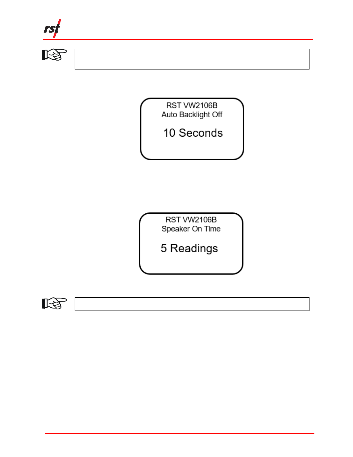
Figure 2-4 Auto Backlight Off.....................................................................................................4
Figure 2-5 Speaker On time.......................................................................................................4
Figure 3-1 Terminal posts ..........................................................................................................5
Figure 3-2 Press down on the terminal post...............................................................................6
Figure 3-3 Correct angle for wire insertion .................................................................................6
Figure 3-4 Slide the wire into the gap.........................................................................................7
Figure 3-5 All wires connected to terminal posts........................................................................7
Figure 3-6 Set time screen.........................................................................................................9
Figure 3-7 Memory screen.......................................................................................................10
Figure 3-8 Create location screen............................................................................................10
Figure 3-9 Selecting the sweep frequency ...............................................................................11
Figure 3-10 Thermistor type.....................................................................................................11
Figure 3-11 One sensor connected..........................................................................................12
Figure 4-1 VW2106 Readout details ........................................................................................13
Figure 4-2 Readings screen.....................................................................................................14
Figure 4-3 Storing a reading.....................................................................................................14
Figure 4-4 Storing a reading with 6 sensors.............................................................................15
Figure 4-5 Data logging interval ...............................................................................................16
Figure 4-6 Data logging number...............................................................................................16
Figure 4-7 Logging screen .......................................................................................................17
Figure 4-8 Zeroing options.......................................................................................................17
Figure 4-9 Delete options.........................................................................................................18
Figure 5-1 Battery compartment...............................................................................................20
Figure 5-2 Battery installation...................................................................................................20
Figure 5-3 Battery voltage screen ............................................................................................21
LIST OF TABLES
Table 4-1 Standard Wiring Colour Codes...................................................................................5
Table 4-2 Standard Wiring Colour Codes...................................................................................8
Table 3-3 Sweep Frequencies .................................................................................................12

VW2106 Vibrating Wire Readout Manual
ELM0042M
RST Instruments Ltd.
Page 1
1 INTRODUCTION
The RST VW2106 Readout is a lightweight device used to read and display vibrating
wire sensor and thermistor data. It is suitable for harsh environments and the user
interface is simple to use.
The VW2106 readout is powered by 3 standard "AA" alkaline batteries to facilitate
replacement in the field. Data can be reviewed either on-board or downloaded to the
computer using RST-provided software.
FIGURE 1-1 VW 2106 READOUT
1. USB Connector
6. Scroll Down
2. Large character LCD display
7. Enter
3. Backlight (hold down to display
Engineering Units)
8. Terminal Posts (for sensor
connection)
4. ESC (navigates back one
menu)
9. Expansion port (VW Load Cells
and external Multiplexers)
5. Scroll Up

VW2106 Vibrating Wire Readout Manual
ELM0042M
RST Instruments Ltd.
Page 2
The latest model of the VW2106 features push post terminals to easily connect VW
Sensor instruments, visual instructions for using the terminal posts and changing the
batteries (Figure 1-2), and a refreshed look.
FIGURE 1-2 VISUAL INSTRUCTIONS FOR TERMINAL POSTS AND BATTERY CHANGES
If you have an older model VW2106, please refer to Section 3.2 for instructions to
connect a single field instrument to the readout. The multi-channel connection
instructions are identical for all models.
1.1 SAFETY
This product is battery operated. There are no major safety concerns associated
with use.
It is important to keep the unit clean during use in the field. Ensure there is no dirt or
dust in the wire terminals, battery compartment, and weather seal along the edge of
the lid of the enclosure. Make sure that weather caps for the USB port and
expansion port are properly secured when not in use.
2 GETTING STARTED
2.1 POWERING ON
The VW2106 Readout unit can be powered on any time by pressing any key.
2.2 POWERING OFF
The VW2106 unit can be powered off either manually or automatically.

VW2106 Vibrating Wire Readout Manual
ELM0042M
RST Instruments Ltd.
Page 3
The following instructions illustrate how to power off the unit manually:
1. Use the up/down arrows to scroll to the Power Off screen (Figure 2-1).
FIGURE 2-1 POWER OFF SCREEN
2. Press Enter and the unit will turn off.
The following instructions detail how to configure the unit to power off automatically.
1. Navigate to the Auto Off screen (Figure 2-2).
FIGURE 2-2 AUTO OFF SCREEN
2. Press Enter. The following screen will appear (Figure 2-3):
FIGURE 2-3 AUTO POWER OFF TIME
3. Use the up/down arrows to scroll to the desired auto power off time. Press Enter
to select the time. The default time is five minutes.

VW2106 Vibrating Wire Readout Manual
ELM0042M
RST Instruments Ltd.
Page 4
NOTE: THE AUTO POWER OFF FEATURE IS ALWAYS ACTIVE TO CONSERVE BATTERY
LIFE AND CANNOT BE DISABLED.
4. The next screen prompts the user to select the Auto Backlight Off (Figure 2-4).
Use the up/down arrows to adjust the desired time and press Enter.
FIGURE 2-4 AUTO BACKLIGHT OFF
5. The next screen prompts the user to select the Speaker On time. Use the
up/down arrows to select the desired time and press Enter. The unit will return to
the previous menu.
FIGURE 2-5 SPEAKER ON TIME
NOTE: KEEP THE UNIT OFF WHEN NOT IN USE TO PRESERVE BATTERY LIFE.
3 CONFIGURATION
The VW2106 may be connected to either single field instruments or multi-channel
instruments.
3.1 SINGLE FIELD INSTRUMENT CONNECTION
The following instructions outlined below to connect single field instruments:
1. Match each wire to its respective terminal post. The posts have colour coded
labels for quick reference (Figure 3-1).

VW2106 Vibrating Wire Readout Manual
ELM0042M
RST Instruments Ltd.
Page 5
FIGURE 3-1 TERMINAL POSTS
Table 3-1 lists matching colours and wire transducers.
TABLE 3-1 STANDARD WIRING COLOUR CODES
Post Colour
Wire Colour
Wire Transducer
Red
Red
Coil +
Black
Black
Coil -
Green
Green
Therm +
White
White
Therm -
Blue
Bare
Shield
CAUTION: MAKE SURE THAT THE WIRES ARE CLEAN AND FREE OF DIRT BEFORE
INSERTING THEM INTO THE TERMINALS.
CAUTION: ENSURE THAT CABLES HAVE ENOUGH SLACK TO FACILITATE
ATTACHMENT.APPROXIMATELY 2” OF SLACK IS RECOMMENDED.
CAUTION: ENSURE THAT THE TERMINALS ARE FREE FROM DIRT AND DEBRIS
BEFORE INSERTING THE WIRES.TERMINALS CAN BE BLOWN OUT WITH COMPRESSED
AIR IF NECESSARY.
2. Firmly press down on the first terminal post (Figure 3-2).

VW2106 Vibrating Wire Readout Manual
ELM0042M
RST Instruments Ltd.
Page 6
FIGURE 3-2 PRESS DOWN ON THE TERMINAL POST
3. Hold the wire parallel to the plane of the readout, to the left of the post, and at a
slight angle to the terminal labels, as illustrated in Figure 3-3.
FIGURE 3-3 CORRECT ANGLE FOR WIRE INSERTION
4. With the post still depressed, slide the stripped end of the instrument cable into
the opening on the matching terminal post (Figure 3-4).

VW2106 Vibrating Wire Readout Manual
ELM0042M
RST Instruments Ltd.
Page 7
FIGURE 3-4 SLIDE THE WIRE INTO THE GAP
5. Release terminal post to secure the wire.
6. Gently tug on the wire to ensure it has been correctly secured.
7. Repeat for all wires (Figure 3-5).
FIGURE 3-5 ALL WIRES CONNECTED TO TERMINAL POSTS
NOTE: APPLYING SOLDER TO THE BARE ENDS OF THE CABLE REDUCES FRAYING
OVER TIME.ALL RST SENSORS ARE PRE-TINNED IN THE FACTORY.
WARNING: ENSURE THERE ARE NO EXPOSED WIRES CONNECTING BETWEEN
ADJACENT PUSH POST TERMINALS.

VW2106 Vibrating Wire Readout Manual
ELM0042M
RST Instruments Ltd.
Page 8
3.2 SINGLE FIELD INSTRUMENT CONNECTION –OLDER MODELS
The following instructions outline the steps to connect single field instruments:
1. Using hands or a screwdriver, lift the gates on the terminal strip.
2. Insert the stripped ends of the instrument cable to the matching wire transducer.
Refer to Table 3-2 for matching colours and wire transducers.
TABLE 3-2 STANDARD WIRING COLOUR CODES
Wire Colour
Wire Transducer
Red
Coil +
Black
Coil -
Green
Therm +
White
Therm -
Bare
Shield
CAUTION: MAKE SURE THAT THE WIRES ARE CLEAN AND FREE OF DIRT BEFORE
INSERTING THEM INTO THE TERMINALS.
CAUTION: ENSURE THAT THE TERMINALS ARE FREE FROM DIRT AND DEBRIS
BEFORE INSERTING THE WIRES.TERMINALS CAN BE BLOWN OUT WITH COMPRESSED
AIR IF NECESSARY.
3. Close each gate to secure the wire.
CAUTION: ENSURE THAT THE GATES ARE SECURED BEFORE CLOSING THE LID TO
THE UNIT TO AVOID DAMAGING THE GATES.
NOTE: APPLYING SOLDER TO THE BARE ENDS OF THE CABLE REDUCES FRAYING
OVER TIME.ALL RST SENSORS ARE PRE-TINNED IN THE FACTORY.
3.3 MULTI-CHANNEL CONNECTION
The VW 2106 may be connected to multi-channel instruments through its expansion
connection (Figure 1-1, 9).
Mating halves of the connectors are available through RST if your current sensors
are not equipped with the appropriate connector.

VW2106 Vibrating Wire Readout Manual
ELM0042M
RST Instruments Ltd.
Page 9
The most common instrument with multiple channels is a Load Cell. Typical load
cells have either 3 or 6 Vibrating Wire sensors with a common thermistor. During
location setup, the number of sensors can be specified. Please refer to section 3.7
for detailed instructions.
The expansion connection is also able to control external multiplexers, which can
facilitate connecting multiple single-channel instruments simultaneously.
For specific applications and configurations, please contact RST Instruments.
3.4 SETTING DATE AND TIME
Each reading includes a date and time stamp and it is stored in the unit’s memory.
To ensure accurate historical records of the readout data, keep the date and time
current.
The following outlines the steps to set the date and time on the readout.
1. Turn on the readout by pressing any key.
2. Scroll to the Set Time screen (Figure 3-6) using the up/down arrows and press
‘Enter’.
FIGURE 3-6 SET TIME SCREEN
3.5 CREATING LOCATIONS
The VW2106 Readout may be pre-configured either using the software on a host
computer or directly on the device.
It is recommended that the VW2106 be pre-configured with the software prior to use
in the field, as the site location names can be defined ahead of time.
If taken directly to the field prior to defining locations, each location will be assigned a
generic name which can be edited once the VW2106 is connected to a host
computer.
NOTE: THE MAXIMUM NUMBER OF PRE-DEFINED LOCATIONS IS 254.

VW2106 Vibrating Wire Readout Manual
ELM0042M
RST Instruments Ltd.
Page 10
The following instructions outline the steps to define new locations and location
parameters on the device.
1. Turn on the readout by pressing any key.
2. Scroll to the Memory screen (Figure 3-7) using the up/down arrows and press
Enter.
FIGURE 3-7 MEMORY SCREEN
3. Scroll to the Create Location screen (Figure 3-8) using the up/down arrows and
press Enter.
FIGURE 3-8 CREATE LOCATION SCREEN
4. The VW2106 will automatically create a site called Location X, where ‘X’ is the
next storage location available in the unit’s memory. Make note of the real
location name in your field notebook and its relation to the location number.
When connected to the Host Software back in the office, a custom name can be
entered, which replaced the site name assigned by the readout.
NOTE: NEW SITES CREATED IN THE FIELD ARE ASSIGNED THE NAME ‘LOCATION X’
BY DEFAULT.THE READOUT AUTOMATICALLY INCREMENTS THE ‘X’ TO THE
NEXT NUMBER AVAILABLE IN THE UNIT’S MEMORY.LOCATION NAMES CAN
ONLY BE CHANGED WHEN THE VW2106 IS CONNECTED TO HOST SOFTWARE.
5. Use the up/down arrows to select between 1 and 6 sensors to read and press
Enter.

VW2106 Vibrating Wire Readout Manual
ELM0042M
RST Instruments Ltd.
Page 11
NOTE: IN MOST CASES,THE SENSOR NUMBER WILL BE EQUAL TO 1. CASES WHERE
MORE THAN ONE SENSOR IS USED ON THE LOAD CELLS REQUIRE THE
EXPANSION CONNECTOR WHICH WILL BE AUTOMATICALLY ENABLED.
6. When connecting a single sensor, you will be given a choice between reading
from the terminal strip or the expansion connector when connecting a single
sensor. Select the appropriate connection and press Enter.
7. Use the up/down arrows to select the appropriate ‘Sweep Frequency’ for the
gauge being measured at that location (Figure 3-9) and press Enter. The default
is the “B” sweep (1200-3550Hz), which is the standard range for the RST model
VW2100 series piezometers. Additional Sweep Frequencies are summarized in
Section 3.7.
FIGURE 3-9 SELECTING THE SWEEP FREQUENCY
8. Use the up/down arrows to select the type of thermistor (Figure 3-10) and press
Enter. The default is 3K, which is the standard thermistor in all RST Vibrating
Wire sensors.
FIGURE 3-10 THERMISTOR TYPE
You may now use the newly created location to store readings. For instructions on
how to store readings, refer to section 4.2.
3.6 IMPORTING PARAMETERS
If at least one location has previously been defined, the following instructions outline
the steps to import parameters.

VW2106 Vibrating Wire Readout Manual
ELM0042M
RST Instruments Ltd.
Page 12
1. Scroll to the Monitor Settings screen using the up/down arrows and press
Enter.
2. Select the Import from Loc. option and scroll to the desired location using the
up/down arrows and press Enter when complete.
The location label will appear at the top of the screen to indicate the current location
in use.
NOTE: THE DEVICE WILL DISPLAY THE MESSAGE “NO LOCATIONS”IF NO LOCATIONS
EXIST IN THE READOUT’S MEMORY.
3.7 CREATING CUSTOM PARAMETERS
The following instructions outline the steps to set up custom parameters.
1. Scroll to the Monitor Settings screen using the up/down arrows and press
Enter.
2. Select the Custom Setup option and press Enter.
3. Select the number of sensors connected and press Enter. Most devices will be
set to connect to one sensor per terminal strip (Figure 3-11). The expansion
connector is automatically enabled when more than one sensor is selected.
FIGURE 3-11 ONE SENSOR CONNECTED
4. Select the appropriate sweep frequency and press Enter. Refer to Table 3-3 for
sweep frequencies corresponding to sensor type.
TABLE 3-3 SWEEP FREQUENCIES
Sweep
Frequency
Sensor Type
A
450-6000Hz
Wide Sweep
B (Default)
1200-3550Hz
Piezometer, Strain Gauge, Borehole Stressmeter, Jointmeter,
Crackmeter, Displacement, Settlement, Temperature, Load
Cells

VW2106 Vibrating Wire Readout Manual
ELM0042M
RST Instruments Ltd.
Page 13
C
450-1200Hz
Arc Weldable Strain Gauge
D
450-1200Hz
Embedment Strain Gauge
E
1000-3600Hz
Spot Weldable Strain Gauge
F
2500-6000Hz
Borehole Stressmeter
U (Custom)
1200-3550Hz
Custom user specified sweep frequency. May only be set within
the readout software.
5. Select the Thermistor Type and press Enter. Options include 2252, 3K (default),
10K, and RTD.
6. Select the desired display units and press Enter.
7. The unit will return to the previous menu.
4 OPERATION
This section describes the operation of the VW2106 Readout once the unit has been
powered on (see Section 2.1).
4.1 STARTUP
Once powered on, an opening screen will appear with the RST Instruments logo. If
the user wishes to view the details of the readout, press any key immediately.
Details of the unit (Figure 4-1) including the model, version number, serial number
and current date and time settings are displayed.
FIGURE 4-1 VW2106 READOUT DETAILS
NOTE: CHECK THAT THE DATE AND TIME SETTINGS ARE CORRECT,AS THIS MAY
AFFECT ANY READINGS STORED IN THE UNIT’S MEMORY.
If no keys are pressed after powering on, the unit will default to the readings screen
(Figure 4-2).

VW2106 Vibrating Wire Readout Manual
ELM0042M
RST Instruments Ltd.
Page 14
FIGURE 4-2 READINGS SCREEN
If a unit is connected, the readings screen will display the current sweep settings and
a reading from the VW instrument and its internal thermistor. The default units are B
units (f2x 10-3) and degrees Celsius. Units can be changed if desired (see section
3.7).
4.2 STORING READINGS IN MEMORY
The VW2106 readout has 128k of internal memory, allowing it to store over 11,000
time-stamped readings.
The following instructions outline the steps required to store readings in the unit’s
memory.
1. Using the up/down arrows, scroll to the Store Data screen and press Enter.
2. Using the up/down arrows, scroll to the desired location and press Enter.
3. Press Enter when prompted to store the reading (Figure 4-3).
FIGURE 4-3 STORING A READING
4. If the unit has more than once sensor, the unit will display both average readings
(in bold) and individual readings (Figure 4-4).
B: 1200 - 3550
9032.7
22.1
B
oC

VW2106 Vibrating Wire Readout Manual
ELM0042M
RST Instruments Ltd.
Page 15
FIGURE 4-4 STORING A READING WITH 6SENSORS
NOTE: AVERAGE READINGS WILL NOT BE STORED IN THE UNIT’S MEMORY.
4.3 REVIEWING DATA
The following instructions outline the steps to review readings on the VW2106.
1. Press any key to turn the readout on.
2. Using the up/down arrows, scroll to the Memory screen and press Enter.
3. Using the up/down arrows, scroll to Review Data and press Enter.
4. Scroll to the desired location using the up/down arrows and press Enter.
5. If a location contains more than one reading, the readings can be scrolled
through using the up/down arrow.
4.4 DATA LOGGING
The VW2106 has a basic datalogging function where the user can set the
datalogging interval and the number of iterations.
The following instructions detail the steps to log data at a given location.
1. Use the up/down arrows to scroll to the Memory screen and press Enter.
2. Use the up/down arrows to scroll to the Data Logging screen and press Enter.
3. Use the up/down arrows to select the location to record the data. If no locations
are currently defined, the readout with respond with “No Locations.” See section
3.5 for detail about how to define locations.
4. Use the up/down arrows to set the reading interval and press Enter. For
example, if 4 is selected, the data will log every 4 seconds (Figure 4-5).

VW2106 Vibrating Wire Readout Manual
ELM0042M
RST Instruments Ltd.
Page 16
FIGURE 4-5 DATA LOGGING INTERVAL
5. Using the up/down arrows, select the data logging number and press Enter. For
example, if the number 4 is selected, the data will log 4 times every interval, as
illustrated in Figure 4-6. To continuously log data until the memory is full, set the
data logging number to 0.
FIGURE 4-6 DATA LOGGING NUMBER
6. The readout will start the data logging process and will end with a message
stating “Logging completed”. ESC can be pressed any time to abort the data
logging process.
4.5 DATA LOGGING THROUGH STORE DATA
Once the intervals and iteration preferences have been defined (see section 4.4 step
4), data logging can also be accessed through the Store Data screen.
1. Using the up/down arrows, scroll to the Store Data screen and press Enter.
2. Select the location where the data will be stored. Press Enter.
3. Press and HOLD the Enter button to commence data logging. The logging
screen will appear (Figure 4-7).
Table of contents