Glasair GLASTAR User manual

KIT: P/N 938-02000-01
KIT INSTRUCTIONS: P/N 063-09019-01
REVISION: C DATE: 8/28/08 PAGE: 1
2008©Copyright Glasair Aviation LLC, Arlington, Washington All rights reserved
GLASTAR / SPORTSMAN
CABIN AIR VENT KIT
ORIGINAL EQUIPMENT INSTRUCTIONS
PARTS LIST: PLEASE REFER TO THE PACKING LIST
This kit provides all the necessary parts and hardware for installing pilot-
and passenger-side cabin air vents. The system draws fresh air into the
cabin through two small but very effective NACA-style scoops on the
fuselage sides. Airflow can be controlled by the pilot and passenger using
two adjustable eyeball ventilators. These ventilators are oversized to
provide ample airflow in hot climates, even at the slower end of the
GlaStar / Sportsman’s wide performance envelope.
The cabin air vent system can be installed in a GlaStar / Sportsman at any
stage of completion, but it is most easily accomplished immediately after
the fiberglass fuselage shells have been bonded together and fastened to
the welded steel-tube cage structure.

KIT: P/N 938-02000-01
KIT INSTRUCTIONS: P/N 063-09019-01
REVISION: C DATE: 8/28/08 PAGE: 2
2008©Copyright Glasair Aviation LLC, Arlington, Washington All rights reserved
Step 1: Cut Out the NACA Scoop in the Fuselage
Side
Figure 6 on the last page of these instructions is a full-size template
of the NACA scoop for the cabin air vents. Glue this template to a
piece of stiff cardboard and cut it out.
Figure 1 shows how the template should be positioned on the
outside of the fuselage shell. The narrow forward edge of the
template should be positioned 3 ½” aft of the cowling attach flange
joggle, and the centerline of the template should be parallel to and
8” below the waterline of the aircraft.
CAUTION: The NACA scoop cutout location given above is taken
from one of our GlaStar / Sportsman demonstrators. However, early
customer experience suggests that, due to variations in the position of
the cage relative to the shells, the specified cutout location may lead to
interference between cage tubes and the cabin air vent boxes.
Therefore, treat this location as provisional until you have verified
clearance, as described below.
Tape the template in position on the exterior of the fuselage shell.
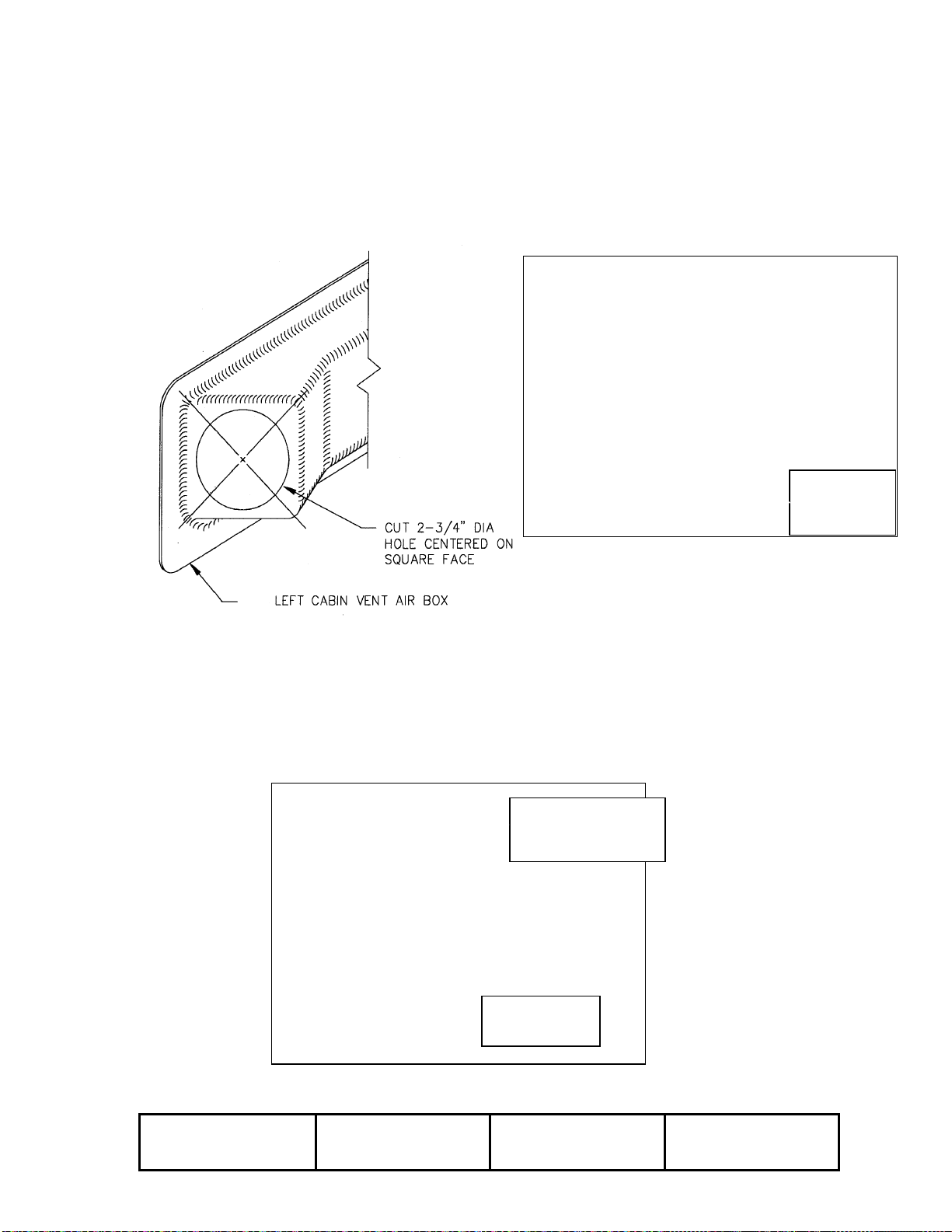
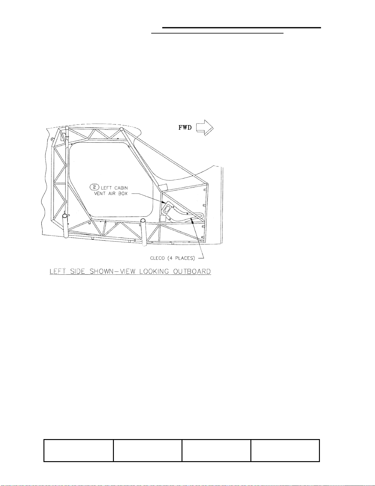
Then position the appropriate air box on the inside of the shell
opposite the template so that the NACA scoop-shaped portion of
the box is aligned with the template (see Figure 3). The box should
clear all cage tubes when pressed against the fuselage shell.
Check both sides and adjust the position of the cutout as necessary
before cutting into the shell. It is acceptable to move the location
as much as several inches from that specified above; however,
take reasonable care to keep the centerline of the cutout parallel
with the aircraft waterline. When you are satisfied that both boxes
will clear, trace around the perimeter of the template with a marking
pen. Then cut all the way through the fuselage shell, removing the
material inside the marked line. Cut slightly inside he line initially
and then finish up the cutout with a file and sandpaper.
CAUTION: Take care not to damage the cage structure behind the
fuselage shell as you make the NACA scoop cutout.
Completed: Left [ ] Right [ ]

KIT: P/N 938-02000-01
KIT INSTRUCTIONS: P/N 063-09019-01
REVISION: C DATE: 8/28/08 PAGE: 3
2008©Copyright Glasair Aviation LLC, Arlington, Washington All rights reserved
FIGURE 1: POSITIONING THE AIR BOX FOR INSTALLATION
5-½”

KIT: P/N 938-02000-01
KIT INSTRUCTIONS: P/N 063-09019-01
REVISION: C DATE: 8/28/08 PAGE: 4
2008©Copyright Glasair Aviation LLC, Arlington, Washington All rights reserved
Step 2: Prepare the Air Box for Installation
The air boxes are installed inside the fuselage shell on each side of
the aircraft to receive the air drawn into the system through the
NACA scoops. The air box in turn provides mounting surface for
the eyeball ventilators.
Prepare the air box for installation by, first trimming the edges down
to the scribe line provided. This will result in a bonding flange
around the entire perimeter of the part approximately 5/8” wide.
Second, use coarse sandpaper, to remove the gelcoat from the
flange all the way around the part.
Sand bonding
flange with 36 grit

KIT: P/N 938-02000-01
KIT INSTRUCTIONS: P/N 063-09019-01
REVISION: C DATE: 8/28/08 PAGE: 5
2008©Copyright Glasair Aviation LLC, Arlington, Washington All rights reserved
FIGURE 2: CUTTING THE VENTILATOR OPENING IN THE AIR BOX
K1000-3
Nutplates (4)
places
Next, as shown in Figure 2 cut a hole for the eyeball ventilator in
the square aft face of the box. Find the center of the face by
marking diagonal lines from the corners, and then use a 2 ¾” hole
saw to cut a circle centered on that point.
Finally, fit the eyeball ventilator into the opening and align the
edges of the square ventilator mounting flange with the edges of
the air box. Mark the four corner hole locations and then drill them
through the air box with a #10 bit.
Pass-drill #10
(4) places
Use temporary
screws or #10 clecos
to hold in position

KIT: P/N 938-02000-01
KIT INSTRUCTIONS: P/N 063-09019-01
REVISION: C DATE: 8/28/08 PAGE: 6
2008©Copyright Glasair Aviation LLC, Arlington, Washington All rights reserved
Position #10
nutplate jig 45°
to corner
Countersink #40
holes for
AN426AD3-3 rivets
Using standard procedures, install a K1000-3 nutplate at each hole
on the inside of the air box. Use 3/32” AN426AD3-3
flush-head rivets.

KIT: P/N 938-02000-01
KIT INSTRUCTIONS: P/N 063-09019-01
REVISION: C DATE: 8/28/08 PAGE: 7
2008©Copyright Glasair Aviation LLC, Arlington, Washington All rights reserved
Cleco K1000-3
nutplates in
position
Completed: Left [ ] Right [ ]
Use hand rivet
squeezer to
secure nutplates

REVISION: C DATE: 8/28/08 PAGE: 8
©2008 Copyright Glasair Aviation LLC, Arlington, Washington All rights reserved
FIGURE 3: BONDING THE AIR BOX
TO THE FUSELAGE SHELL
Step 3: Install the Air Box
The air box is molded with a dogleg in it to aim the eyeball ventilator
directly at the occupants of the aircraft, as well as to allow them to
reach it easily for adjustment. This geometry also allows the box to
fit inside the cage structure at the mounting location. Figure 3
shows the general layout of the air box relative to the cage.
Align the pre-molded
NACA scoop section of
the air box with the cutout
you made in Step 1.
Verify that the air box
clears the cage structure
and relieve the mounting
flange, if necessary, to
achieve a good fit. When
you are satisfied, use a
#40 bit to drill four index
holes through the
mounting flange of the air
box and the inner
fuselage laminates only.
You will insert clecos into
these holes to hold the
box in position during the
bonding process.
Remove the air box and use coarse sandpaper to roughen the
inside of the fuselage shell around the NACA scoop cutout. Then
clean both the shell and the air box mounting flange with Acetone.

KIT: P/N 938-02000-01
KIT INSTRUCTIONS: P/N 063-09019-01
REVISION: C DATE: 8/28/08 PAGE: 9
2008©Copyright Glasair Aviation LLC, Arlington, Washington All rights reserved
Mix a small batch of thick resin / milled fiber mixture and spread it
evenly over the air box mounting plate. Position the box against
the fuselage side and use four clecos to pin it in place. Then, using
the NACA scoop and the eyeball opening for access, reach inside
the air box and make a smooth fillet wherever excess resin / milled
fiber mixture has oozed out. Let cure.
Completed: Left [ ] Right [ ]

KIT: P/N 938-02000-01
KIT INSTRUCTIONS: P/N 063-09019-01
REVISION: C DATE: 8/28/08 PAGE: 10
2008©Copyright Glasair Aviation LLC, Arlington, Washington All rights reserved
Step 4: Fill and Contour the Edges of the NACA
Scoop
To harden the edges of the fuselage where the NACA scoop cutout
has been made and to provide a solid basis for contouring these
edges as required, it is necessary to route out some of the foam
core of the fuselage shell all the way around the perimeter of the
scoop cutout. Use a utility knife or a metal pick to gouge out a
trough between the inner and outer laminates approximately ¼”
deep all the way around the cutout. At the aft edge of the cutout,
increase the depth of this trough to about ½”.
Once you have removed the foam core as described above, fill the
resulting troughs back in with Bondo or resin/Q-cell paste mix or
some other similar body filler. After this has cured, sand a smooth,
square corner into the upper and lower edges of the cutout, sand
and fill as necessary to achieve a smooth blending of the fuselage
side into the NACA scoop portion of the air box, but don’t worry that
there remains a fairly steep slope at this point from the fuselage
side into the scoop.
After the scoop has been sanded to your satisfaction, you can
primer or re-gelcoat the exposed surfaces.
Completed: Left [ ] Right [ ]
Make this radius ¼” diameter
(reverse airfoil shape)
Sand / blend corners into
fuselage with 1/8” radius

KIT: P/N 938-02000-01
KIT INSTRUCTIONS: P/N 063-09019-01
REVISION: C DATE: 8/28/08 PAGE: 11
2008©Copyright Glasair Aviation LLC, Arlington, Washington All rights reserved
FIGURE 4: FINISHING THE NACA SCOOP EDGES

KIT: P/N 938-02000-01
KIT INSTRUCTIONS: P/N 063-09019-01
REVISION: C DATE: 8/28/08 PAGE: 12
2008©Copyright Glasair Aviation LLC, Arlington, Washington All rights reserved
Step 5: Install the Eyeball Ventilators
As shown in Figure 5, use NAS603-8P round-head machine screws
to install the eyeball ventilator in the air box.
Note: If you intend to upholster over your air boxes, you will want to do
so before installing the ventilators.
Completed: Left [ ] Right [ ]
√
FIGURE 5: INSTALLING THE EYEBALL VENTILATOR
Install eyeball
ventilators with (4)
NAS603-8P machine
sc
r
e
w
s
Blend inside edges with
filler. Primer and Zolotone
to match interior

KIT: P/N 938-02000-01
KIT INSTRUCTIONS: P/N 063-09019-01
REVISION: C DATE: 8/28/08 PAGE: 13
2008©Copyright Glasair Aviation LLC, Arlington, Washington All rights reserved
FIGURE 6: NACA SCOOP TEMPLATE (FULL SIZE)
6.0
2 3/4
This manual suits for next models
1
Other Glasair Aircraft manuals